Address Resolution Protocol
Abstract
In this chapter, you will learn about the hardware addressing used in the data link layer frame and how it is found by the sender. We’ll talk a lot about the hardware addresses used on LANs, the MAC addresses.
You will learn about the ARP protocol, which is how IP stacks on LANs identify the hardware address that the destination field of the frame should use.
Keywords
address resolution; MAC address; hardware address
In this chapter, you will learn about the hardware addressing used in the data link layer frame and how it is found by the sender. We’ll talk a lot about the hardware addresses used on LANs, the MAC addresses.
You will learn about the ARP protocol, which is how IP stacks on LANs identify the hardware address that the destination field of the frame should use.
The Internet, or any internetwork, is made up of a combination of physical networks such as LANs and internetworking devices such as routers. A packet sent by a host might pass through several different physical networks before finally reaching its destination.
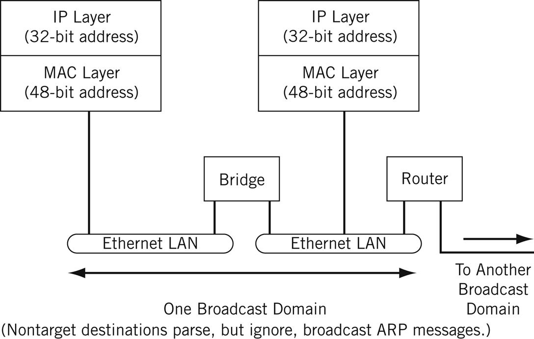
The hosts and routers at the network layer are identified by their network addresses (also sometimes called “logical addresses”). In TCP/IP, the network or logical address is the IP address, as we saw in the last chapter. These addresses are usually implemented in software, and must be globally unique on the Internet. At the data link layer, the interface that sends and receives frames is identified by the physical or hardware address. An example of a hardware address is the 48-bit MAC address we have been seeing at the frame level. (See Figure 6.1.)
The hardware address and the network address are two different identifiers with different sizes, but we need both of them. Layered protocol stacks can use different types of packets (such as IPv4 and IPv6) on the same Ethernet. Also, IPv4 packets can be sent over an Ethernet link and then over a point-to-point link with a very different frame structure.
However, we need some way to map back and forth between addresses at the network and hardware levels. In TCP/IP, this mapping is provided by the address resolution protocols (the technical term is bindings). ARP results are stored in an ARP cache on a host so that the entire process does not have to be constantly repeated. And to keep the MAC table from constantly getting bigger and bigger, the table entries are purged periodically.
The main address resolution protocol is the Address Resolution Protocol (ARP) itself, but there are also Reverse ARP (RARP), proxy ARP, Inverse ARP (InARP), and ARP for ATM networks (ATMARP). Other ARPs have been proposed as well (such as a generic “WARP” for ARPs on a wide area network). In many ways, the various ARP flavors are not really separate protocols. For that reason, only the main ARP will be described in detail in this chapter. The purposes of the other members of the ARP family will be mentioned, but they are not used very often, and not at all on the Illustrated Network.
Most implementations allow the static entry of ARP IP-address-to-physical-address information as permanent entries into the ARP cache. However, this poses an administrative nightmare (many organizations have a hard enough time keeping track of IP addresses alone) and is seldom done today. Most ARP tables today are built and maintained dynamically.
ARP and LANs
Let’s see how the Illustrated Network uses ARP to map IPv4 addresses to physical addresses. We can look at some ARPs sent by FreeBSD, Linux, and Windows, and see what they look like. Then we can examine the ARP caches and see what information is kept and how it is stored.
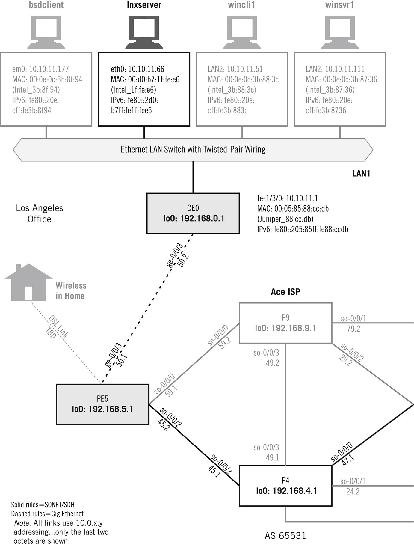
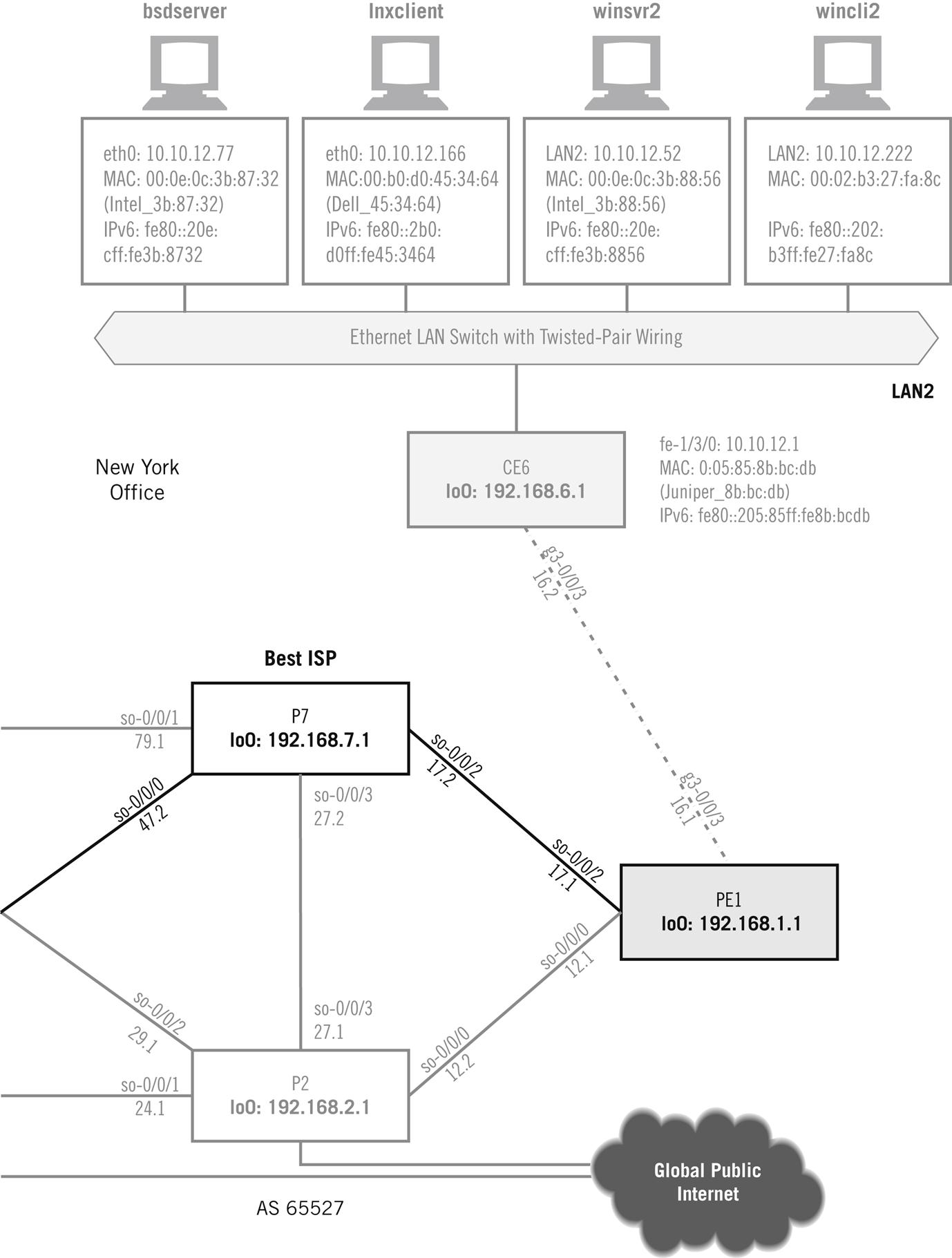
Figure 6.1 shows the devices on the Illustrated Network that we’ll be working with in this chapter. This time we’ll be using the hosts on each LAN and a pair of routers.
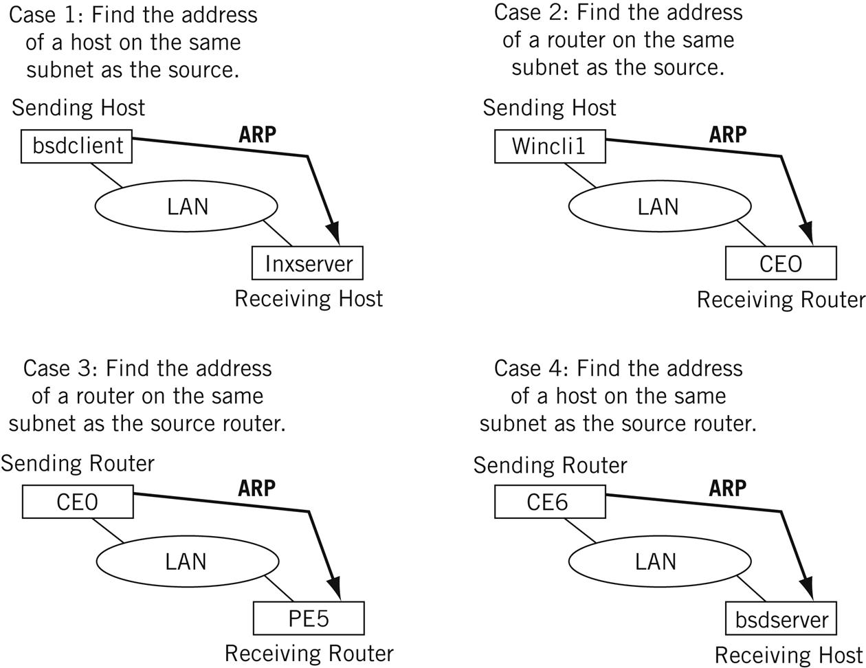
We’ll use these hosts and routers to look at four different cases where ARP is used, as shown in Figure 6.2.
Host to host—The ARP sender is a host and wants to send a packet to another host on the same LAN. In this case, the IP address of the destination is known and the MAC address of the destination must be found.
Host to router—The ARP sender is a host and wants to send a packet to another host on a different LAN. A forwarding (routing) table is used to find the IP address of the router. In this case, the IP address of the router is known and the MAC address of the router must be found.
Router to router—The ARP sender is a router and wants to forward a packet to another router on the same LAN. A forwarding (routing) table is used to find the IP address of the router. In this case, the IP address of the router is known and the MAC address of the destination router must be found.
Router to host—The ARP sender is a router and wants to forward a packet to a host on the same LAN. In this case, the IP address of the host is known (from the IP destination address on the packet) and the MAC address of the host must be found.
Let’s look at Case 1 in detail because the others are more or less variations on this basic theme. In Case 1, ARP is used when a host wants to send to another host on the same IP subnet and the MAC address of the destination is not already known. We’ll start the LAN2 host lnxclient sending a short message to winsrv2 (it doesn’t really matter what the message is). Because this is the first time that these devices have communicated in a long time, an ARP request is broadcast on LAN2 and the sender waits for a reply.
Now let’s capture the ARP request and response pair on the lnxclient host at IPv4 address 10.10.12.166. We’ll set a filter to only capture and display ARP packets.
root@lnxclient admin]# /usr/sbin/tethereal -V arp
Capturing on eth0
Frame 1 (42 bytes on wire, 42 bytes captured)
Arrival Time: May 5, 2008 22:13:40.148457000
Time delta from previous packet: 0.000000000 seconds
Time relative to first packet: 0.000000000 seconds
Frame Number: 1
Packet Length: 42 bytes
Capture Length: 42 bytes
Ethernet II, Src: 00:b0:d0:45:34:64, Dst: ff:ff:ff:ff:ff:ff
Destination: ff:ff:ff:ff:ff:ff (Broadcast)
Source: 00:b0:d0:45:34:64 (Dell_45:34:64)
Type: ARP (0x0806)
Address Resolution Protocol (request)
Hardware type: Ethernet (0x0001)
Protocol type: IP (0x0800)
Hardware size: 6
Protocol size: 4
Opcode: request (0x0001)
Sender MAC address: 00:b0:d0:45:34:64 (Dell_45:34:64)
Sender IP address: 10.10.12.166 (10.10.12.166)
Target MAC address: 00:00:00:00:00:00 (00:00:00_00:00:00)
Target IP address: 10.10.12.52 (10.10.12.52)
Frame 2 (106 bytes on wire, 106 bytes captured)
Arrival Time: May 5, 2008 22:13:40.148642000
Time delta from previous packet: 0.000185000 seconds
Time relative to first packet: 0.000185000 seconds
Frame Number: 2
Packet Length: 106 bytes
Capture Length: 106 bytes
Ethernet II, Src: 00:0e:0c:3b:88:56, Dst: 00:b0:d0:45:34:64
Destination: 00:b0:d0:45:34:64 (Dell_45:34:64)
Source: 00:0e:0c:3b:88:56 (00:0e:0c:3b:88:56)
Type: ARP (0x0806)
Trailer: 00000000000000000000000000000000…
Address Resolution Protocol (reply)
Hardware type: Ethernet (0x0001)
Protocol type: IP (0x0800)
Hardware size: 6
Protocol size: 4
Opcode: reply (0x0002)
Sender MAC address: 00:0e:0c:3b:88:56 (00:0e:0c:3b:88:56)
Sender IP address: 10.10.12.52 (10.10.12.52)
Target MAC address: 00:b0:d0:45:34:64 (Dell_45:34:64)
Target IP address: 10.10.12.166 (10.10.12.166)
We’ll look at the fields of an ARP in detail later. For now, note that the ARP request, indicated by a 0x0806 in the Ethertype field goes out as a broadcast frame with an all-zero MAC address field. It’s looking for the MAC address that goes with IP address 10.10.12.52 (winsrv2), the target IP address. The ARP reply frame returns the reply with the correct MAC address plugged into the all-zero field (and with the MAC address as the source address in the frame).
The results of an ARP pair between the bsdclient host (10.10.11.177) and the lnxserver host (10.10.11.66) is almost the same, but not quite. The frame sent in reply to the ARP is smaller than before.
bsdclient# tethereal -V arp
Capturing on em0
Frame 1 (42 bytes on wire, 42 bytes captured)
Arrival Time: May 5, 2008 22:24:04.518213000
Time delta from previous packet: 0.000000000 seconds
Time since reference or first frame: 0.000000000 seconds
Frame Number: 1
Packet Length: 42 bytes
Capture Length: 42 bytes
Ethernet II, Src: 00:0e:0c:3b:8f:94, Dst: ff:ff:ff:ff:ff:ff
Destination: ff:ff:ff:ff:ff:ff (Broadcast)
Source: 00:0e:0c:3b:8f:94 (10.10.11.177)
Type: ARP (0x0806)
Address Resolution Protocol (request)
Hardware type: Ethernet (0x0001)
Protocol type: IP (0x0800)
Hardware size: 6
Protocol size: 4
Opcode: request (0x0001)
Sender MAC address: 00:0e:0c:3b:8f:94 (10.10.11.177)
Sender IP address: 10.10.11.177 (10.10.11.177)
Target MAC address: 00:00:00:00:00:00 (00:00:00_00:00:00)
Target IP address: 10.10.11.66 (10.10.11.66)
Frame 2 (60 bytes on wire, 60 bytes captured)
Arrival Time: May 5, 2008 22:24:04.518421000
Time delta from previous packet: 0.000208000 seconds
Time since reference or first frame: 0.000208000 seconds
Frame Number: 2
Packet Length: 60 bytes
Capture Length: 60 bytes
Ethernet II, Src: 00:d0:b7:1f:fe:e6, Dst: 00:0e:0c:3b:8f:94
Destination: 00:0e:0c:3b:8f:94 (10.10.11.177)
Source: 00:d0:b7:1f:fe:e6 (10.10.11.66)
Type: ARP (0x0806)
Trailer: 000000000000000000000000000000000000
Address Resolution Protocol (reply)
Hardware type: Ethernet (0x0001)
Protocol type: IP (0x0800)
Hardware size: 6
Protocol size: 4
Opcode: reply (0x0002)
Sender MAC address: 00:d0:b7:1f:fe:e6 (10.10.11.66)
Sender IP address: 10.10.11.66 (10.10.11.66)
Target MAC address: 00:0e:0c:3b:8f:94 (10.10.11.177)
Target IP address: 10.10.11.177 (10.10.11.177)
The reply from the Linux system is only 60 bytes, 46 bytes less than the response from the Windows server in the first example. That’s interesting; let’s take a closer look at what Windows is doing. Figure 6.3 shows a graphical capture of the reply from winsrv2 (10.10.12.52) to an ARP request from wincli2 (10.10.12.222).
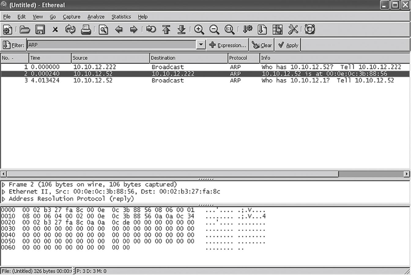
The reply is indeed 106 bytes long, but the extra bits are all zeros. The only difference in the replies is the number of trailing zeroes in the frame. And we can also see that the ARP software can deal with these easily.
We’ve already mentioned that ARP results are cached. The devices that send the ARP requests cache the results, and the device that receives the ARP usually also caches the MAC address in the arriving ARP request. The idea is that if one device in a pair sends in one direction, the other device in the pair will probably send in the opposite direction as well.
Let’s look at the ARP cache on the bsdserver host (10.10.12.77) using the -a (all) option.
bsdserver# arp -a
? (10.10.12.1) at 00:05:85:8b:bc:db on em0 [ethernet]
? (10.10.12.52) at 00:0e:0c:3b:88:56 on em0 [ethernet]
? (10.10.12.166) at 00:b0:d0:45:34:64 on em0 [ethernet]
? (10.10.12.222) at 00:02:b3:27:fa:8c on em0 [ethernet]
All four other devices on LAN2 are represented (don’t forget the router CE6). The question marks are there because we have no DNS running at the moment. Let’s see if we can add to the cache by sending a ping to the Windows server (winsrv1) on LAN1.
bsdserver# ping 10.10.11.111
PING 10.10.11.111 (10.10.11.111): 56 data bytes
64 bytes from 10.10.11.111: icmp_seq=0 ttl=126 time=0.403 ms
64 bytes from 10.10.11.111: icmp_seq=1 ttl=126 time=0.413 ms
64 bytes from 10.10.11.111: icmp_seq=2 ttl=126 time=0.376 ms
^C
--- 10.10.11.111 ping statistics ---
3 packets transmitted, 3 packets received, 0% packet loss
round-trip min/avg/max/stddev = 0.376/0.397/0.413/0.016 ms
bsdserver# arp -a
? (10.10.12.1) at 00:05:85:8b:bc:db on em0 [ethernet]
? (10.10.12.52) at 00:0e:0c:3b:88:56 on em0 [ethernet]
? (10.10.12.166) at 00:b0:d0:45:34:64 on em0 [ethernet]
? (10.10.12.222) at 00:02:b3:27:fa:8c on em0 [ethernet]
Nothing was added to the ARP cache on the FreeBSD server. Then again, why should it be? The other host is only reachable through a router, and the router’s ARP entry is already there (10.10.12.1). These common types of ARPs, host to host ARPs, are only used when the destination is on the same LAN subnet as the source.
Entries in the ARP cache are deleted when no communication occurs with another device, usually after 300 seconds (5 minutes) of silence between the devices. We can force the ARP cache to empty by using the –d (delete) option.
bsdserver# arp -d -a
10.10.12.1 (10.10.12.1) deleted
10.10.12.52 (10.10.12.52) deleted
10.10.12.166 (10.10.12.166) deleted
10.10.12.222 (10.10.12.222) deleted
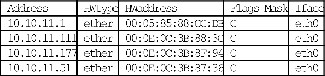
In Linux, the command to display the ARP cache is the same (arp), but the -e option displays the result in the “default” Linux format (using no option gives the same result). The “C” means that the entry is “complete.”
[root@lnxserver admin]# /sbin/arp
| Address | HWtype | HWaddress | Flags Mask | Iface |
| 10.10.11.1 | ether | 00:05:85:88:CC:DB | C | eth0 |
| 10.10.11.111 | ether | 00:0E:0C:3B:88:3C | C | eth0 |
| 10.10.11.177 | ether | 00:0E:0C:3B:8F:94 | C | eth0 |
| 10.10.11.51 | ether | 00:0E:0C:3B:87:36 | C | eth0 |
[root@lnxserver admin]# /sbin/arp -e
| Address | HWtype | HWaddress | Flags Mask | Iface |
| 10.10.11.1 | ether | 00:05:85:88:CC:DB | C | eth0 |
| 10.10.11.111 | ether | 00:0E:0C:3B:88:3C | C | eth0 |
| 10.10.11.177 | ether | 00:0E:0C:3B:8F:94 | C | eth0 |
| 10.10.11.51 | ether | 00:0E:0C:3B:87:36 | C | eth0 |

In Linux, use of the -a option displays the results in “BSD” style. The output is still slightly different, however.
[root@lnxserver admin]# /sbin/arp -a
? (10.10.11.1) at 00:05:85:88:CC:DB [ether] on eth0
? (10.10.11.111) at 00:0E:0C:3B:88:3C [ether] on eth0
? (10.10.11.177) at 00:0E:0C:3B:8F:94 [ether] on eth0
? (10.10.11.51) at 00:0E:0C:3B:87:36 [ether] on eth0
Windows displays the ARP cache with arp -a as well. This output is from winsrv2 on LAN2.
C:\Users\walterg>arp -a
Interface: 10.10.12.52 --- 0x1003
| Internet Address | Physical Address | Type |
| 10.10.12.1 | 00-05-85-8b-bc-db | dynamic |
| 10.10.12.77 | 00-0e-0c-3b-87-32 | dynamic |
| 10.10.12.166 | 00-b0-d0-45-34-64 | dynamic |
| 10.10.12.222 | 00-02-b3-27-fa-8c | dynamic |
The term dynamic distinguishes these entries from statically defined entries.
There is no separate ARP for IPv6. MAC addresses can be embedded in the IPv6 addresses, but this does not solve the problem of a source host knowing the physical address of a destination host or router. When a host uses IPv4-derived IPv6 addresses, such as ::10.10.11.111, IPv4 ARP information can be used to supply the MAC addresses for IPv6.
The address resolution process in IPv6 uses ICMPv6 messages and is part of the Neighbor Discovery (ND) process. Generally, a multicast Neighbor Solicitation message is sent and a unicast Neighbor Advertisement message is received in reply. We’ll talk more about this process in the chapter on ICMPv6. For now, let’s just verify that IPv6 address resolution uses ICMPv6 messages.
Wireshark can capture and display IPv6 traffic as well as IPv6. Let’s send a test message using the link-local IPv6 addresses from winsrv1 to wincli1, and capture the address resolution in action. We’ll capture everything but only display ICMPv6 messages. The result is shown in Figure 6.4.
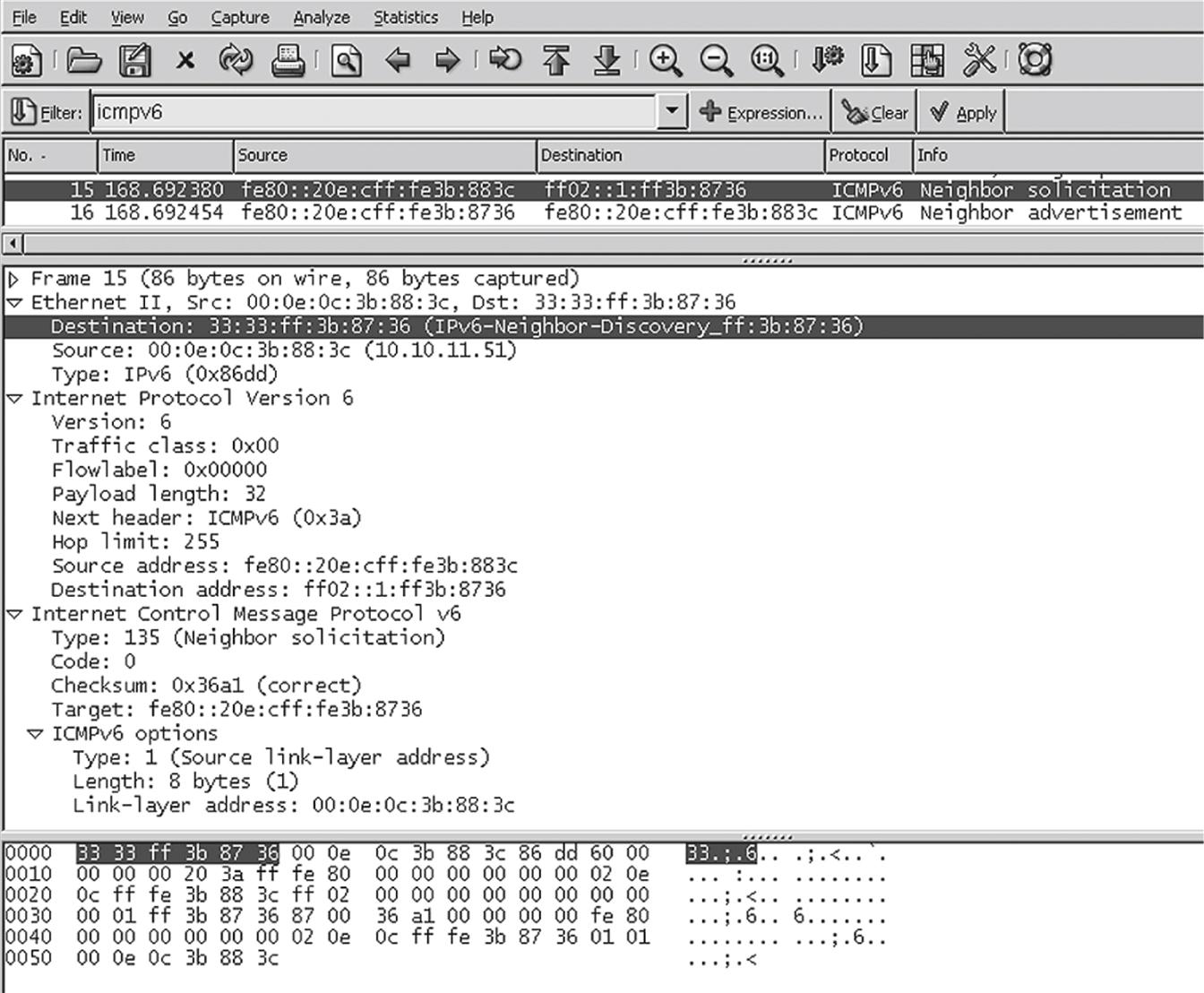
Figure 6.4 shows the details of the Neighbor Solicitation message. The frame destination address is highlighted in the figure, showing that a special multicast frame address is used instead of the ARP broadcast frame address. The major differences between this procedure and the ARP process in IPv4 are that ICMPv6 is used in IPv6, and the solicitation message is sent to the IPv6 multicast group address associated with the target address.
ARP Packets
ARP uses packets, but these are not IP packets. ARP messages ride inside Ethernet frames, or any LAN frame, in exactly the same way as IP packets. There is no need to use an IP address here anyway: ARP frames are valid only for a particular LAN segment and never leave the local LAN (i.e., ARP messages cannot be routed). The structure of an ARP message is shown in Figure 6.5.
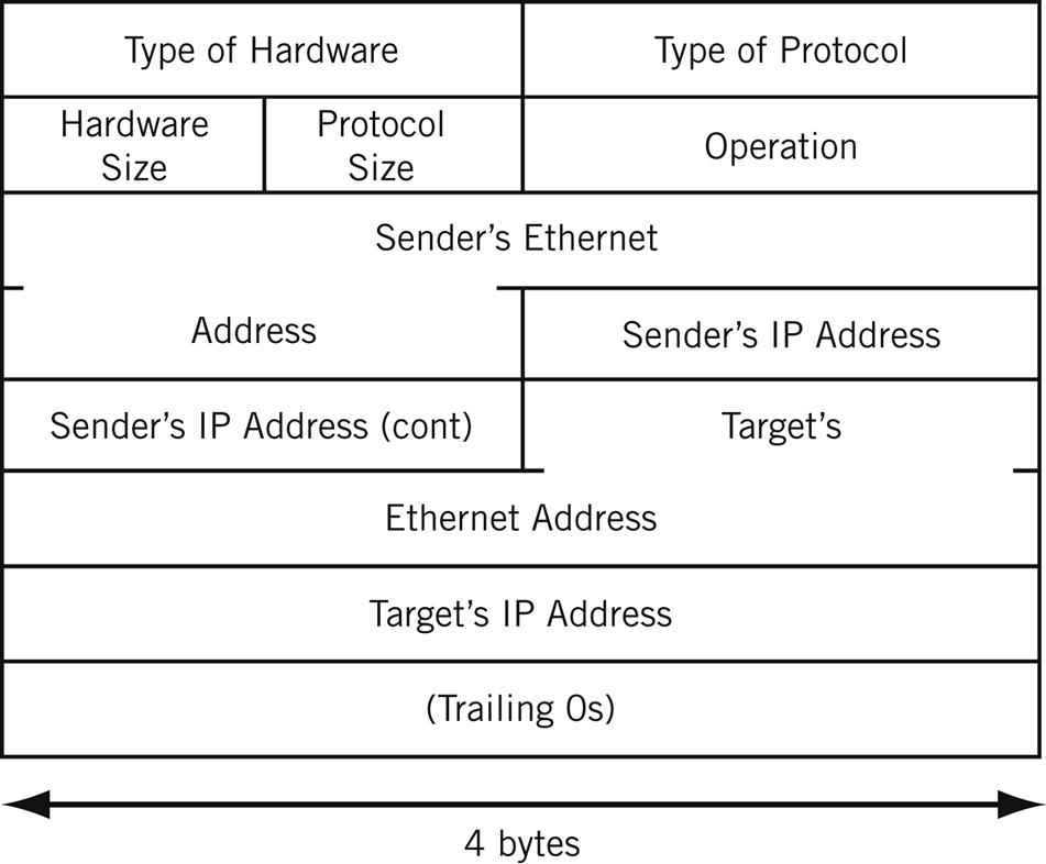
This figure is because the 28-byte ARP message includes fields 1, 2, 4, and 6 bytes in length, and does not readily lend itself to “normal” 32-bit representation. The first five fields form a type of message header. The next four fields are the sender’s and target’s IP and MAC addresses. Usually, it’s the target’s MAC address that needs to be found with the ARP process. And as we have already seen, the ARP message can end with a variable number of trailing zeros.
On an Ethernet LAN, ARP messages have their own Ethertype value (0x0806). However, some ARP implementations used the “regular” Ethertype for IP packets (0x0800) because the IP implementation itself can easily decide if the information inside the frame is IPv4 (packet starts with 0x04) or an ARP message (packet starts with 0x0001 for Ethernet).
The main fields are present in both ARP request and ARP reply messages:
Type of Hardware—This 2-byte field is used to identify the style of hardware address. (The Ethernet-style MAC address, with value=1, is the most common, of course.)
Type of Protocol—This 2-byte field identifies the type of Layer 3, or network layer, protocol that is being queried. (ARP messages, because they are not IP packets, can be used for more than IP addresses.) This uses the same set of values as the Ethertype field, so IP is 0x0800.
Hardware Size—This byte identifies the size, in bytes, of the hardware address. The Ethernet MAC address is 6 bytes long.
Protocol Size—This byte identifies the size, in bytes, of the Layer 3 protocols. IPv4 addresses are 4 bytes long.
Operation—This 2-byte field identifies the ARP message’s intent. For example, an ARP request (“Who has this IPv4 address?”) has the operation value of 1 and a reply value of 2.
The rest of the fields do not have a fixed size. Their size is determined by the value in the Hardware Size and Protocol Size fields. On our Ethernet LANs, the hardware address size is 6 bytes (MAC) and the protocol address size is 4 bytes (IPv4). In that case, the sizes and functions of these fields are as follows.
Sender’s Ethernet Address—This 6-byte field holds the sender’s Ethernet address. It should be the same as the source address in the Ethernet frame.
Sender’s IP Address—This 4-byte field holds the sender’s Ethernet address. (This is how targets fill in their own ARP caches without requiring more ARPs.)
Target’s Ethernet Address—This 6-byte field holds the target’s Ethernet address. This field in set to all 0 bits in a request. The reply will have this field filled in and the operation changed to “reply.”
Target’s IP Address—This 4-byte field holds the target’s IPv4 address.
Example ARP Operation
What the ARP process adds to TCP/IP is a mechanism for a source device to ask, “Who has IP address 10.10.12.52 (this was our first example from the Illustrated Network) and what is the physical (hardware) address associated with it?”
ARP messages are broadcast frames sent to all stations. The proper destination IP layer realizes that the destination IP address in the packet matches its own and replies directly to the sender. The target device replies by simply reversing the source and destination IP address in the ARP packet. The target also uses its own hardware address as the source address in the frame and message.
The ARP process is shown in Figure 6.6. The steps are numbered and taken from the example earlier in this chapter, where lnxclient ARPs to find the MAC address of winsvr2.
1. The system lnxclient (10.10.12.166) assembles an ARP request and sends it as a broadcast frame on the LAN. Because it is unknown, the requested MAC address field in the ARP message uses all zeros (0s), which are placeholders.
2. All devices attached to the LAN receive and process the broadcast, even the router CE6. But only the device with the target’s IP address in the ARP message (winsvr2 at 10.10.12.52) replies to the ARP. The target also caches the MAC address associated with 10.10.12.166 (the source address in the broadcast frame).
3. The target system winsvr2 sends a unicast ARP reply message back to lnxclient. The reply has the MAC address requested both in the frame (as a source address) and in the ARP message field sent as 0s.
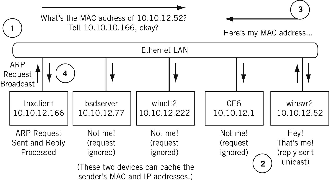
The originating source system and the target system will cache the hardware address of the destination and proceed to send “live” IP packets with the information, at the same time supplying the proper frame address as a parameter to the network access layer software.
Figure 6.7 shows how the ARP request and reply message shown at the beginning of this chapter look like “on the wire.” The field values can be compared to the ARP message format shown in Figure 6.5. Again, the lnxclient to winsrv2 ARP pair are used as the example. Trailing zeros are not shown.
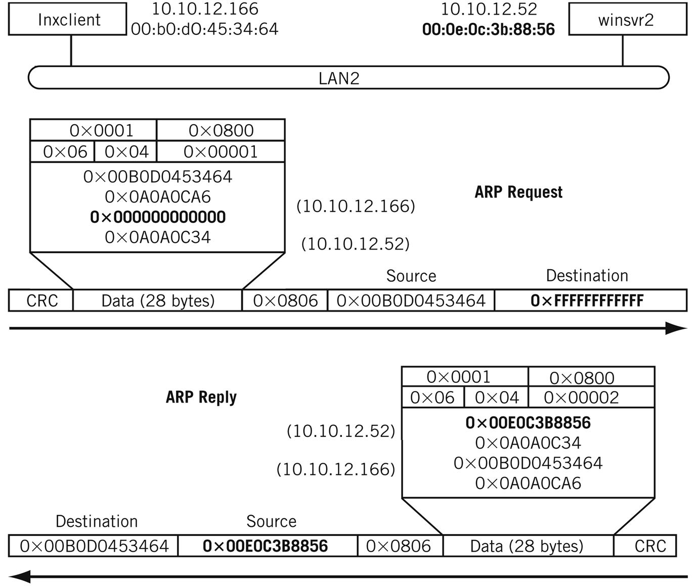
ARP operation is completely transparent to the user. ARP operation is usually triggered when a user runs some TCP/IP application, such as FTP, and the frame’s destination MAC address is not in the ARP cache.
ARP Variations
ARP is a fairly straightforward procedure to determine the LAN hardware address that goes with a given IP address. However, there are more network types than LANs and there are more “addresses” that need to be associated with IP addresses than “hardware” addresses. Consequently, there are a few other types of ARPs that have evolved to deal with other IP network situations.
Proxy ARP
Proxy ARP is an older technique (it was called the “ARP Hack”) that was used in early routers, and is still supported in some routers today. LANs connected by bridges had hosts that did not (and could not) use different IP network addresses. The same IP network address is used on both sides of a bridge, so there is one broadcast domain, and ARPs are shuttled back and forth. This practice wasted bandwidth on the LANs (and on any WAN link between the bridges). Proxy ARP allowed the router that replaced the bridge to respond to ARP requests directly with its own MAC address, without having to propagate the ARP packets onto the other LAN segment. Hosts then sent frames to the router, but acted as if they were sending the frames directly to the destination host. Proxy ARP makes sure that the router received the frame, just as with indirect delivery.
Routers normally require that the same IP subnet address not be configured on more than one router port. Proxy ARP was a method of assigning a single Class A, B, or C address to both sides of router without using subnet masking, allowing the router to function as a bridge. Proxy ARP was useful as networking transitioned from bridges to routers.
Proxy ARP is still often used in Mobile IP networks, which often bridge between devices.
Reverse ARP
Reverse ARP (RARP) is used in cases where a device on a TCP/IP network knows its physical (hardware) address but must determine the IP address associated with it. A RARP request (“I have MAC address X … What’s my IP address?”) is sent to a device running the RARP server process. The RARP server replies with the IP address of the device. The RARP server should be located on the local LAN segment, but it does not have to be.
RARP messages use the same packet format as ARP, but the Ethertype is 0x0835, and the operation field is 3 for a RARP request and 5 for a RARP reply. Of course, the information to be supplied is the IP address. As with ARP, the request is broadcast and the reply is unicast. RARP is defined in RFC 903.
RARP was frequently used for diskless network devices on TCP/IP networks such as workstations, X-terminals, routers, and hubs. These devices needed to obtain variable configuration information such as the IP address for an external source whenever they were rebooted or powered on. In addition, the amount of configuration information you could obtain through RARP was very limited. Today, with almost every device having flash memory to store configuration information during reboot when power is off, the need for RARP is greatly diminished.
Even in cases where configuration information or IP addresses need to be assigned dynamically, there are better ways to achieve the same result than with RARP, such as BOOTP and DHCP. Both will be discussed in Chapter 22 of this book.
ARPs on WANs
On most WANs, ARP is still used, but as a limited multicast rather than a broadcast. ARP has a couple of variations used to address WAN environments such as frame relay and ATM networks. These public network technologies use virtual circuits (a type of logical connection) at the frame (frame relay) or cell (ATM) level instead of MAC addresses. The issue in frame relay and ATM (both called non-broadcast multiaccess [NBMA] link networks) is to find the virtual circuit number, such as the Data Link Connection Identifier (DLCI) in frame relay, associated with a particular IP address.
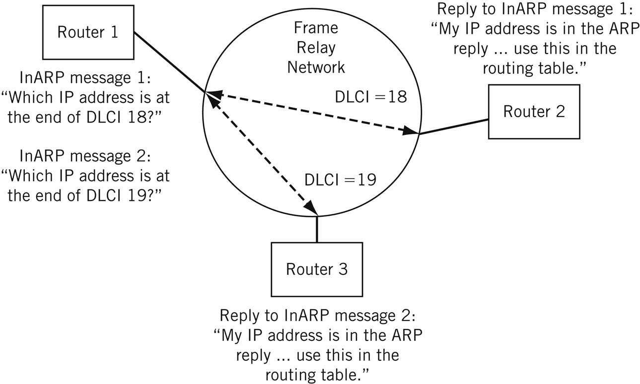
InARP (Inverse ARP) was developed for use on frame relay networks. Instead of using ARP to determine MAC-layer LAN addresses, TCP/IP networks linked by frame relay networks use InARP to determine the IP address at the other end of a frame relay DLCI number to use when sending IP packets. InARP is used as soon as frame relay DLCI are created. The replies are used to build the routing table in the frame relay access device (router). The InARP process is shown in Figure 6.8. InARP is essentially an adaptation of the reverse ARP (RARP) process used on LANs.
ATMARP is a similar method used to find the ATM virtual path identifier (VPI) and/or virtual channel identifier (VCI) over an ATM network.
ARP and IPv6
IPv6 really has no need for a separate ARP function. Instead, the Neighbor Discovery protocol (ND, sometimes NDP) described in RFC 2461 performs the functions of the IPv4 ARP in IPv6.
ND is really a superset of most of the functions of IPv4’s ARP, ICMP Redirect, and ICMP Router Discovery features. This section will discuss some of the features of NDP, but most of this will be covered in the chapter on ICMP.
Neighbor Discovery Protocol
The Neighbor Discovery protocol is the way that IPv6 hosts and routers find things out about their immediate neighborhood, typically the LAN segment. A lot of effort was expended in IPv4 to find out configuration necessities such as default routers, any alternate routers, MAC addresses of adjacent hosts, and so on. In some cases, these addresses could not be found automatically with IPv4 and had to be entered manually (the default router). IPv6 was designed to be almost automatic in this regard.
When an IPv6 host comes up for the first time, the host advertises its MAC layer address and asks for neighbor and router information. Because these messages are in the form of ICMPv6 messages, only the basics will be presented here.
The ARP function in IPv6 is performed by four messages in ND. The Router Solicitation/Router Advertisement mechanism is noteworthy in that it provides the key for host IPv6 address configuration, default route selection, and potentially even bootstrap configuration information.
Neighbor Solicitation—This message is sent by a host to find out the MAC layer address of another host. It is also used for Duplicate Address detection (Does another host have the same IPv6 address?) and for Neighbor Unreachability Detection (Is the other host still there?). The receiving host must reply with a Neighbor Advertisement.
Neighbor Advertisement—This message contains the MAC layer address of the host and is sent in reply to a Neighbor Solicitation message. Hosts also send unsolicited Neighbor Advertisement when they first start up or if any of the advertised information changes.
Router Solicitation—This message is sent by a host to find routers. The receiving router must reply with a Router Advertisement.
Router Advertisement—This message contains the MAC layer address of the router and is sent in reply to a Router Solicitation message. Routers also send an unsolicited Router Advertisement when they first start up if any of the advertised information changes.
ND Address Resolution
ND functions are performed only for local IPv6 addresses (the hop limit is set to 1 for these messages). ND messages, unlike ARP, are not broadcast (“Everyone pay attention to this”) but rather multicast (“Only those interested pay attention to this”).
When an IPv6 host or router starts up, it joins several multicast groups. The IPv6 mode must join the all-nodes group. It must also join a solicited-node group for each interface running IPv6 or IPv6 address that the node has. Joining these groups allows the device to receive packets without having all the details of its address established. This is a much more sophisticated arrangement than the ARP method used in IPv4. The IPv6 device must keep these multicast groups active until all of its addressing details have been resolved.
When an IPv6 device needs to resolve the MAC layer address of another host on the LAN, a Neighbor Solicitation message is sent to the solicited-node multicast address. The IPv6 solicited-node multicast address is formed by taking the low-order 24 bits of the IPv6 address and adding the 104-bit prefix FF02::1 to it. Thus, for the link-local IPv6 address fe80::20e:cff:fe3b:883c, the IPv6 multicast group address used is fe02::1: fe3b:883c.
But what multicast address should the message use in the Ethernet frame? That multicast address is formed by prepending 33:33 to the lower 24 bits of the IPv6 address. Each device with an IP address registers this form with the local NIC and expects to receive ND messages this way initially. For the IPv6 multicast group address fe02::1:fe3b:883c, the multicast address used in the Ethernet destination field is 33:33:fe:3b:88:3c.
An example of the address resolution pair capture earlier in this chapter is shown in Figure 6.9. Note the use of multicast IPv6 and frame addresses in the Neighbor Solicitation request and the way the information is supplied in the unicast Neighbor Announcement reply.
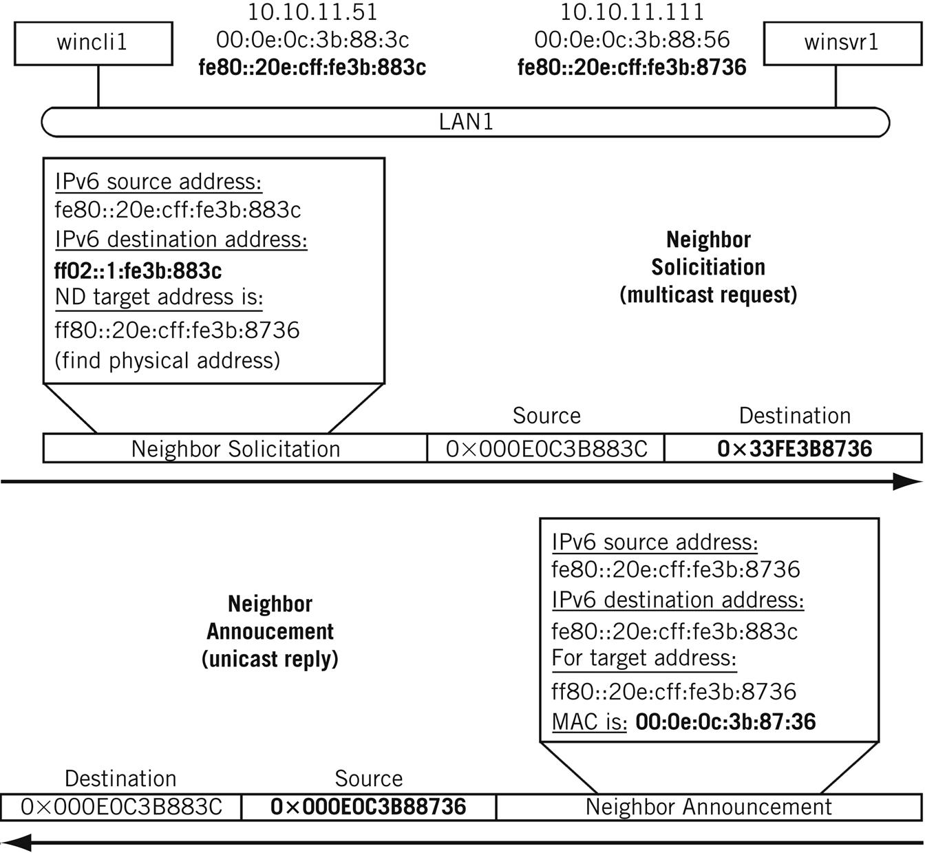
If no response is received, the sender can generate the Neighbor Solicitation message several times. When a Neighbor Advertisement message is received by the sender, the content is used to update the IPv6 Neighbor cache (the equivalent of the IPv4 ARP cache).
More details on ND message formats and operation are discussed in the ICMP chapter.
Questions for Readers
Figure 6.10 shows some of the concepts discussed in this chapter and can be used to help you answer the following questions.
1. Why can’t the same address structure and value be used for network layer and hardware addresses?
2. Why do ARPs have to pass through bridges, but should not pass through routers?
3. Why does a receiver place the sender’s MAC address in its own ARP cache?
4. What is Proxy ARP used for?
5. What is the advantage of using multicast groups instead of broadcasts for address resolution?