Transmission Control Protocol
Abstract
In this chapter, you will learn about the TCP transport layer protocol, which is the connection-oriented, more reliable companion of UDP. We’ll talk about all the fields in the TCP header (which are many) and how TCP’s distinctive three-way handshake works.
You will learn how TCP operates during the data transfer and disconnect phase, as well as some of the options that have been established to extend TCP’s use for today’s networking conditions.
Keywords
TCP; FTP; UDP; ISN; ECN; RFCs; SYN data; ACK; LAN
In this chapter, you will learn about the TCP transport layer protocol, which is the connection-oriented, more reliable companion of UDP. We’ll talk about all the fields in the TCP header (which are many) and how TCP’s distinctive three-way handshake works.
You will learn how TCP operates during the data transfer and disconnect phase, as well as some of the options that have been established to extend TCP’s use for today’s networking conditions.
The Transmission Control Protocol (TCP) is as complex as UDP is simple. Some of the same concepts apply to both because both TCP and UDP are end-to-end protocols. Sockets and ports, well-known, dynamic, and private, apply to both. TCP is IP protocol 6, but the ports are usually the same as UDP and run from 0 to 65,535. The major difference between UDP and TCP is that TCP is connection oriented. And that makes all the difference.
Internet specifications variously refer to connections as “virtual circuits,” “flows,” or “packet-switched services,” depending on the context. These subtle variations are unnecessary for this book, and we simply use the term “connection.” A connection is a logical relationship between two endpoints (hosts) on a network. Connections can be permanent (although the proper term is “semipermanent”) or on demand (often called “switched”). Permanent connections are usually set up by manual configuration of the network nodes. (On the Internet, this equates to a series of very specific static routes.) On-demand connections require some type of signaling protocol to establish connections on the fly, node by node through the network from the source (the “caller”) host to the destination (the “callee”) host.
Permanent connections are like intercoms: You can talk right away or at any time and know the other end is there. However, you can only talk to that specific endpoint on that connection. On-demand connections are like telephone calls: You have to wait until the other end “answers” before you talk or send any information, but you connect to (call) anyone in the world.
TCP and Connections
As much as router discussions become talks about IP packets and headers, host discussions tend to become talks about TCP. However, a lot of the demonstrations involving TCP revolve around things that can go wrong. What happens if an acknowledgment (ACK) is lost? What happens when two hosts send almost simultaneous connection requests (SYN) to open a connection? With the emphasis on corner cases, many pages written on TCP become exercises in exceptions. Yet there is much to be learned about TCP just by watching it work in a normal, error-free environment.
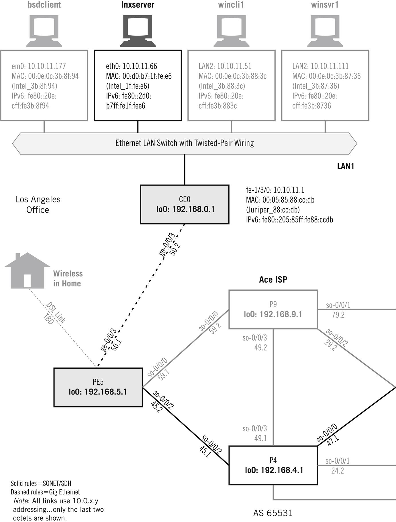
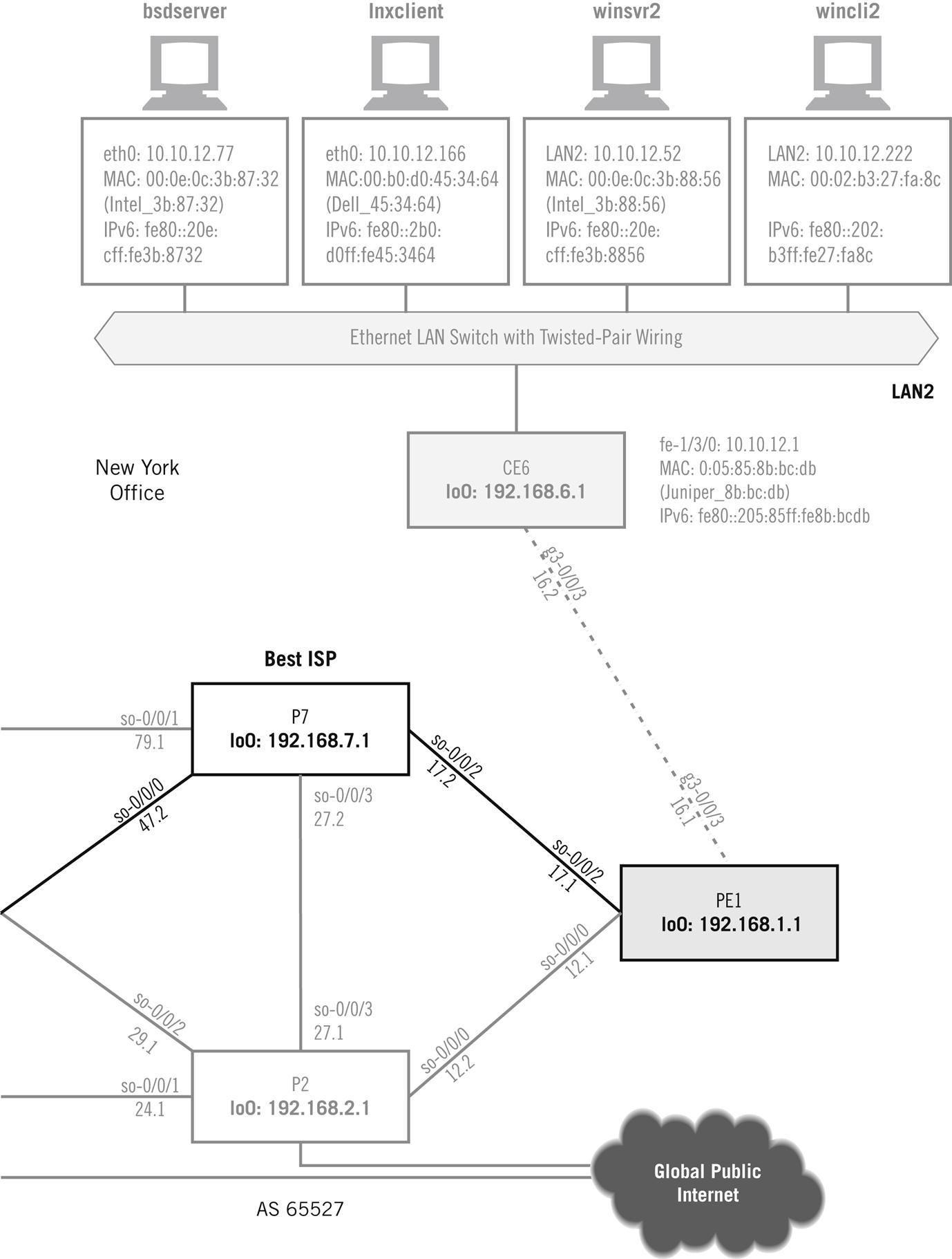
Instead of watching to check whether TCP recovers from lost segments (it does), we’ll just capture the sequence of TCP segments used on various combinations of the three operating system platforms and see what’s going on. Later, we’ll use an FTP data transfer between wincli2 and bsdserver (both on LAN2) to look at TCP in action. In many ways it is an odd protocol, but we’ll only look at the basics and examine FTP in detail in a later chapter. Figure 12.1 shows these hosts on the network.
As before, we’ll use Wireshark to look at frames and packets. There is also a utility called tcpdump, which is bundled with almost every TCP/IP implementation. The major exception, as might be expected, is Windows. The Windows versions, windump (for older versions of Windows) and win10pcap (for newer versions, such as Windows 10, which can capture VLAN information), are not much different than our familiar Wireshark, so we’ll just use Wireshark to capture our Windows TCP sessions. Because TCP operation is complicated, let’s look at some details of TCP operation before looking at how TCP looks on the Illustrated Network.
The TCP Header
The TCP header is the same for IPv4 and IPv6 and is shown in Figure 12.2. We’ve already talked about the port fields in the previous chapter on UDP. Only the features unique to TCP are described in detail.
Source and destination port—In some Unix implementations, source port numbers between 1024 and 4999 are called ephemeral ports. If an application does not specify a source port to use, the operating systems will use a source port number in this range. This range can be expanded and changed (but not always), and 49,152 through 65,535 is more in line with current standards. Use of ephemeral ports impacts firewall use and limits the number of connections a host can have open at any one time.
Sequence number—Each new connection (re-tries of failed connections do not count) uses a different initial sequence number (ISN) as the basis for tracking segments. Windows uses a very simple time-based formula to compute that ISN, while Unix ISNs are more elaborate (ISNs can be spoofed by hackers).
Acknowledgment number—This number must be greater than or equal to zero (even a TCP SYN consumes one sequence number) except for the all 1’s ISN. All segments on an established connection must have this bit set. If there is no actual data in the received segment, the acknowledgment number increments by 1. (Every byte in TCP is still counted, but that’s not all that contributes to the sequence number field.)
Header length—The TCP header length in 4-byte units.
Reserved—Four bits are reserved for future use.
ECN flags—The two explicit congestion notification (ECN) bits are used to tell the host when the network is experiencing congestion and send windows should be adjusted.
URG, ACK, PSH, RST, SYN, FIN—These six single-bit fields (Urgent, Acknowledgment, Push, Reset, Sync, and Final) give the receiver more information on how to process the TCP segment. Table 12.1 shows their functions.
Window size—The size of receive window that the destination host has set. This field is used in TCP flow control and congestion control. It should not be set to zero in an initial SYN segment.
Checksum—An error-checking field on the entire TCP segment and header as well as some fields from the IP datagram (the pseudo-header). The fields are the same as in UDP. If the checksum computed does not match the received value, the segment is silently discarded.
Urgent pointer—If the URG control bit is set, the start of the TCP segment contains important data that the source has placed before the “normal” contents of the segment data field. Usually, this is a short piece of data (such as CTRL-C). This field points to the first nonurgent data byte.
Options and padding—TCP options are padded to a 4-byte boundary and can be a maximum of 40 bytes long. Generally, a 1-byte Type is followed by a 1-byte Length field (including these initial 2 bytes), and then the actual options. The options are listed in Table 12.2.
Table 12.1
TCP Control Bits by Abbreviation and Function
| Bit | Function |
| URG | If set, the Urgent Pointer field value is valid (often resulting from an interrupt-like CTRL-C). Seldom used, but intended to raise the priority of the segment. |
| ACK | If set, the Acknowledgment Number field is valid. |
| PSH | If set, the receiver should not buffer the segment data, but pass them directly to the application. Interactive applications use this, but few others. |
| RST | If set, the connection should be aborted. A favorite target of hackers “hijacking” TCP connections, a series of rules now govern proper reactions to this bit. |
| SYN | If set, the hosts should synchronize sequence numbers and establish a connection. |
| FIN | If set, the sender had finished sending data and initiated a close of the connection. |
Table 12.2
TCP Option Types, Showing Abbreviation (Meaning), Length, and RFC in Which Established
| Type | Meaning | Total Length and Description | RFC |
| 0 | EOL | 1 byte, indicates end of option list (only used if end of options is not end of header) | 793 |
| 1 | NOP | 1 byte, no option (used as padding to align header with Header-Length Field) | 793 |
| 2 | MSS | 4 bytes, the last 2 of which indicate the maximum payload that one host will try to send another. Can only appear in SYN and does not change. | 793879 |
| 3 | WSCALE | 3 bytes, the last establishing a multiplicative (scaling) factor. Supports bit-shifted window values above 65,535. | 1072 |
| 4 | SACKOK | 2 bytes, indicating that selective ACKs are permitted. | 2018 |
| 5 | SACK | Of variable length, these are the selective ACKs. | 1072 |
| 6 | Echo | 6 bytes, the last 4 of which are to be echoed. | 1072 |
| 7 | Echo reply | 6 bytes, the last 4 of which echo the above. | 1072 |
| 8 | Timestamp | 10 bytes, the last 8 of which are used to compute the retransmission timer through the RTT calculation. Makes sure that an old sequence number is not accepted by the current connection. | 1323 |
| 9 | POC perm | 2 bytes, indicating that the partial order service is permitted. | 1693 |
| 10 | POC profile | 3 bytes, the last carrying 2-bit flags. | 1693 |
| 11 | CC | 6 bytes, the last 4 providing a segment connection count. | 1644 |
| 12 | CCNEW | 6 bytes, the last 4 providing new connection count. | 1644 |
| 13 | CCECHO | 6 bytes, the last 4 echoing previous connection count. | 1644 |


TCP Mechanisms
It might not be obvious why TCP connections should be such a complication. One of the reasons is that TCP adds more to connectionless IP than connection capability. The TCP service also provides aspects of what the ISO-RM defines as Session Layer services, services that include the history (a popular term is “state variables”) of the connection progress. Connections also provide a convenient structure with which to associate QoS parameters, although every layer of any protocol stack always has some QoS duties to perform, even if it is only error checking.
Officially, TCP is a virtual circuit service that adds reliability to the IP layer, reliability that is lacking in UDP. TCP also provides sequencing and flow control to the host-to-host interaction, which in turn provides a congestion control mechanism to the routing network as a whole (as long as TCP, normally an end-to-end concern, is aware of the congested condition). The flow control mechanism in TCP is a sliding window procedure that prevents senders from overwhelming receivers and applies in both directions of a TCP connection.
TCP was initially defined in RFC 793, refined in RFCs 879, 1106, 1110, and 1323 (which obsoleted RFC 1072 and RFC 1185). RFCs 1644 and 1693 extended TCP to support transactions, which can be loosely understood as “connection-oriented request–response pairs that cannot use UDP.” RFC 3168 added explicit congestion notification (ECN) bits to the TCP header, which we will see again in the chapter on Cloud computing and large data centers. These bits were “added” by redefining bits 6 and 7 in the TOS field of the packet header.
TCP headers can be between 20 bytes (typical) and 60 bytes long when options are used (not often). A segment, which is the content of a TCP data unit, is essentially a portion of the application’s send buffer. As bytes accumulate in the send buffer, they will exceed the maximum segment size (MSS) established for the connection. These bytes receive a TCP header and are sent inside an IP packet. There are also ways to “push” a partially full send buffer onto the network.
At the receiver, the segment is added to a receive buffer until complete or until the application has enough data to process. Naturally, the amount of data exchanged varies greatly.
Let’s look at how TCP works and then examine the header fields that make it all happen. It might seem strange to talk about major TCP features before the TCP header has been presented, but the operation of many of the fields in the TCP header depend on terminology and concepts used during TCP connection and other procedures.
Connections and the Three-Way Handshake
TCP establishes end-to-end connections over the unreliable, best-effort IP packet service using a special sequence of three TCP segments sent from client to server and back called a three-way handshake. Why three ways? Because packets containing the TCP segment that ask a server to accept another connection and the server’s response might be lost on the IP router network, leaving the hosts unsure of exactly what is going on. The third message adds to the overall reliability.
Once the three segments are exchanged, data transfer can take place from host to host in either direction. Connections can be dropped by either host with a simple exchange of segments (four in total), although the other host can delay the dropping until final data are sent, a feature rarely used.
TCP uses unique terminology for the connection process. A single bit called the SYN (synchronization) bit is used to indicate a connection request. This single bit is still embedded in a complete 20-byte (usually) TCP header, and other information, such as the initial sequence number (ISN) used to track segments, is sent to the other host. Connections and data segments are acknowledged with the ACK bit, and a request to terminate a connection is made with the FIN (final) bit.
The entire TCP connection procedure, from three-way handshake to data transfer to disconnect, is shown in Figure 12.3. TCP also allows for the case where two hosts perform an active open at the same time, but this is unlikely.

This example shows a small file transfer to a server (with the server sending 1000 bytes back to the client) using 1000-byte segments, but only to make the sequence numbers and acknowledgments easier to follow. The whole file is smaller than the server host’s receive window and nothing goes wrong (but things often go wrong in the real world).
Note that to send even one exchange of a request–response pair inside segments, TCP has to generate seven additional packets. This is a lot of packet overhead, and the whole process is just slow over high latency (delay) links. This is one reason that UDP is becoming more popular as networks themselves become more reliable. We’ll talk more about the limitations of TCP in a section at the end of this chapter.
Connection Establishment
Let’s look at the normal TCP connection establishment’s three-way handshake in some detail. The three messages establish three important pieces of information that both sides of the connection need to know.
1. The ISNs to use for outgoing data (in order to deter hackers, these should not be predictable).
2. The buffer space (window) available locally for data, in bytes.
3. The Maximum Segment Size (MSS) is a TCP Option and sets the largest segment that the local host will accept. The MSS is usually the link MTU size minus the 40 bytes of the TCP and IP headers, but many implementations use segments of 512 or 536 bytes (it’s a maximum, not a demand).
A server issues a passive open and waits for a client’s active open SYN, which in this case has an ISN of 2000, a window of 5840 bytes and an MSS of 1460 (common because most hosts are on Ethernet LANs). The window is almost always a multiple of the MSS (1460×4=5840 bytes). The server responds with a SYN and declares the connection open, setting its own ISN to 4000, and “acknowledging” sequence number 2001 (it really means “the next byte I get from you in a segment should be numbered 2001”). The server also established a window of 8760 bytes and an MSS of 1460 (1460×6=8760 bytes).
Finally, the client declares the connection open and returns an ACK (a segment with the ACK bit set in the header) with the sequence number expected (2001) and the acknowledgment field set to 4001 (which the server expects). TCP sequence numbers count every byte on the data stream, and the 32-bit sequence field allows more than 4 billion bytes to be outstanding (nevertheless, high-speed transports such as Gigabit Ethernet roll this field over too quickly for comfort, so special “scaling” mechanisms are available for these link speeds).
TCP’s three-way handshake has two important functions. It makes sure that both sides know that they are ready to transfer data and it also allows both sides to agree on the initial sequence numbers, which are sent and acknowledged (so there is no mistake about them) during the handshake. Why are the initial sequence numbers so important? If the sequence numbers are not randomized and set properly, it is possible for malicious users to hijack the TCP session (which can be reliable connections to a bank, a store, or some other commercial entity). Each device chooses a random initial sequence number to begin counting every byte in the stream sent. How can the two devices agree on both sequence number values in about only three messages? Each segment contains a separate sequence number field and acknowledgment field. In Figure 12.3, the client chooses an initial sequence number (ISN) in the first SYN sent to the server. The server ACKs the ISN by adding one to the proposed ISN (ACKs always inform the sender of the next byte expected) and sending it in the SYN sent to the client to propose its own ISN. The client’s ISN could be rejected, if, for example, the number is the same as used for the previous connection, but that is not considered here. Usually, the ACK from the client both acknowledges the ISN from the server (with server’s ISN + 1 in the acknowledgment field) and the connection is established with both sides agreeing on ISN. Note that no information is sent in the three-way handshake; it should be held until the connection is established.
This three-way handshake is the universal mechanism for opening a TCP connection. Oddly, the RFC does not insist that connections begin this way, especially with regard to setting other control bits in the TCP header (there are three others in addition to SYN and ACK and FIN). Because TCP really expects some control bits to be used during connection establishment and release, and others only during data transfer, hackers can cause a lot of damage simply by messing around with wild combinations of the six control bits, especially SYN/ACK/FIN, which asks for, uses, and releases a connection all at the same time. For example, forging a SYN within the window of an existing SYN would cause a reset. For this reason, developers have become more rigorous in their interpretation of RFC 793.
Data Transfer
Sending data in the SYN segment is allowed in transaction TCP, but this is not typical. Any data included are accepted, but are not processed until after the three-way handshake completes. SYN data are used for round-trip time measurement (an important part of TCP flow control) and network intrusion detection (NID) evasion and insertion attacks (an important part of the hacker arsenal).
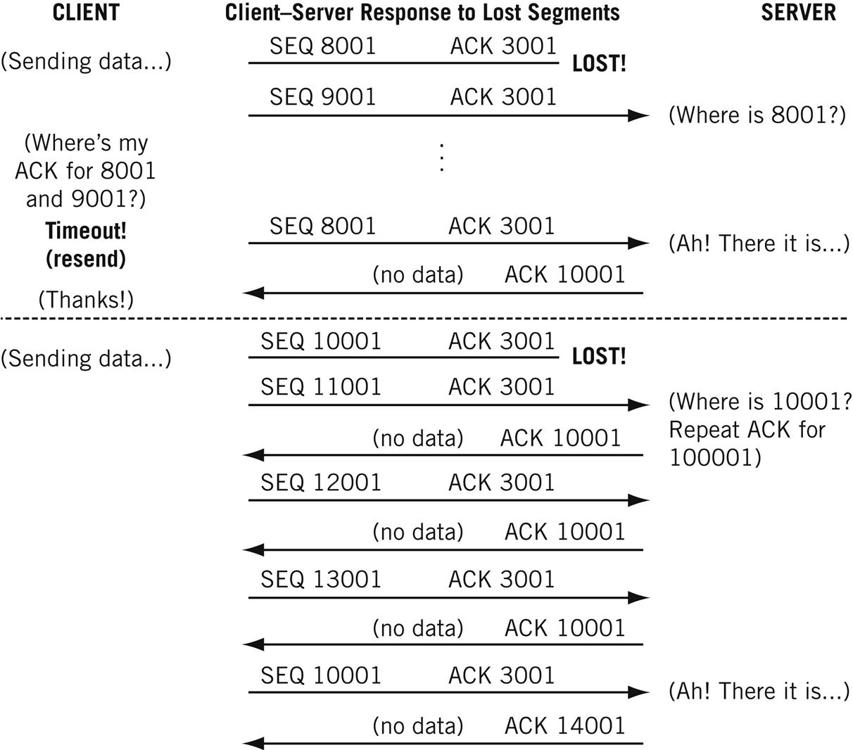
The simplest transfer scenario is one in which nothing goes wrong (which, fortunately, happens a lot of the time). Figure 12.4 shows how the interplay between TCP sequence numbers (which allow TCP to properly sequence segments that pop out of the network in the wrong order) and acknowledgments allow both sides to detect missing segments.
The client does not need to receive an ACK for each segment. As long as the established receive window is not full, the sender can keep sending. A single ACK covers a whole sequence of segments, as long as the ACK number is correct.
Ideally, an ACK for a full receive window’s worth of data will arrive at the sender just as the window is filled, allowing the sender to continue to send at a steady rate. This timing requires some knowledge of the round-trip time (RTT) to the partner host and some adjustment of the segment-sending rate based on the RTT. Fortunately, both of these mechanisms are available in TCP implementations.
What happens when a segment is “lost” on the underlying “best-effort” IP router network? There are two possible scenarios, both of which are shown in Figure 12.4.
In the first case, a 1000-byte data segment from the client to the server fails to arrive at the server. Why? It could be that the network is congested, and packets are being dropped by overstressed routers. Public data networks such as frame relay and ATM (Asynchronous Transfer Mode) routinely discard their frames and cells under certain conditions, leading to lost packets that form the payload of these data units.
If a segment is lost, the sender will not receive an ACK from the receiving host. After a timeout period, which is adjusted periodically, the sender resends the last unacknowledged segment. The receiver then can send a single ACK for the entire sequence, covering received segments beyond the missing one.
But what if the network is not congested and the lost packet resulted from a simple intermittent failure of a link between two routers? Today, most network errors are caused by faulty connectors that exhibit specific intermittent failure patterns that steadily worsen until they become permanent. Until then, the symptom is sporadic lost packets on the link at random intervals. (Predictable intervals are the signature of some outside agent at work.)
Waiting is just a waste of time if the network is not congested and the lost packet was the result of a brief network “hiccup.” So TCP hosts are allowed to perform a “fast recovery” with duplicate ACKs, which is also shown in Figure 12.4.
The server cannot ACK the received segments 11,001 and subsequent ones because the missing segment 10,001 prevents it. (An ACK says that all data bytes up to the ACK have been received.) So every time a segment arrives beyond the lost segment, the host only ACKs the missing segment. This basically tells the other host “I’m still waiting for the missing 8001 segment.” After several of these are received (the usual number is three), the other host figures out that the missing segment is lost and not merely delayed and resends the missing segment. The host (the server in this case) will then ACK all of the received data.
The sender will still slow down the segment sending rate temporarily, but only in case the missing segment was the result of network congestion.
Closing the Connection
Either side can close the TCP connection, but it’s common for the server to decide just when to stop. The server usually knows when the file transfer is complete, or when the user has typed logout and takes it from there. Unless the client still has more data to send (not a rare occurrence with applications using persistent connections), the hosts exchange four more segments to release the connection.
In the example, the server sends a segment with the FIN (final) bit set, a sequence number (whatever the incremented value should be), and acknowledges the last data received at the server. The client responds with an ACK of the FIN and appropriate sequence and acknowledgment numbers (no data were sent, so the sequence number does not increment).
The TCP releases the connection and sends its own FIN to the server with the same sequence and acknowledgment numbers. The server sends an ACK to the FIN and increments the acknowledgment field but not the sequence number. The connection is down.
But not really. The “best-effort” nature of the IP network means that delayed duplicated could pop out of a router at any time and show up at either host. Routers don’t do this just to be nasty, of course. Typically, a router that hangs or has a failed link rights itself and finds packets in a buffer (which is just memory dedicated for communications) and, trying to be helpful, sends them out. Sometimes routing loops cause the same problem.
In any case, late duplicates must be detected and disposed of (which is one reason the ISN space is 32 bits—about 4 billion—wide). The time to wait is supposed to be twice as long as it could take a packet to have its TTL go to zero, but in practice this is set to 4 minutes (making the packet transit time of the Internet 2 minutes, an incredibly high value today, even for Cisco routers, which are fond of sending packets with the TTL set to 255).
The wait time can be as high as 30 minutes, depending on TCP/IP implementation, and resets itself if a delayed FIN pops out of the network. Because a server cannot accept other connections from this client until the wait timer has expired, this often led to “server paralysis” at early Web sites.
Today, many TCP implementations use an abrupt close to escape the wait-time requirement. The server usually sends a FIN to the client, which first ACKs and then sends a RST (reset) segment to the server to release the connection immediately and bypass the wait-time state.
Flow Control
Flow control prevents a sender from overwhelming a receiver with more data than it can handle. With TCP, which resends all lost data, a receiver that is discarding data that overflows the receive buffers is just digging itself a deeper and deeper hole.
Flow control can be performed by either the sender or the receiver. It sounds strange to have senders performing flow control (how could they know when receivers are overwhelmed?), but that was the first form of flow control used in older networks.
Many early network devices were printers (actually, teletype machines, but the point is the same). They had a hard enough job running network protocols and printing the received data, and could not be expected to handle flow control as well. So the senders (usually mainframes or minicomputers with a lot of horsepower for the day) knew exactly what kind of printer they were sending to and their buffer sizes. If a printer had a two-page buffer (it really depended on byte counts), the sender would know enough to fire off two pages and then wait for an acknowledgment from the printer before sending more. If the printer ran out of paper, the acknowledgment was delayed for a long time, and the sender had to decide whether it was okay to continue or not.
Once processors grew in power, flow control could be handled by the receiver, and this became the accepted method. Senders could send as fast as they could, up to a maximum window size. Then senders had to wait until they received an acknowledgment from the receiver. How is that flow control? Well, the receiver could delay the acknowledgments, forcing the sender to slow down, and usually could also force the sender to shrink its window. (Receivers might be receiving from many senders and might be overwhelmed by the aggregate.)
Flow control can be implemented at any protocol level or even every protocol layer. In practice, flow control is most often a function of the transport layer (end to end). Of course, the application feeding TCP with data should be aware of the situation and also slow down, but basic TCP could not do this.
TCP is a “byte-sequencing protocol” in which every byte is numbered. Although each segment must be acknowledged, one acknowledgment can apply to multiple segments, as we have seen. Senders can keep sending until the data in all unacknowledged segments equals the window size of the receiver. Then the sender must stop until an acknowledgment is received from the receiving host.
This does not sound like much of a flow control mechanism, but it is. A receiver is allowed to change the size of the receive window during a connection. If the receiver finds that it cannot process the received window’s data fast enough, it can establish a new (smaller) window size that must be respected by the sender. The receiver can even “close” the window by shrinking it to zero. Nothing more can be sent until the receiver has sent a special “window update ACK” (it’s not ACKing new data, so it’s not a real ACK) with the new available window size.
The window size should be set to the network bandwidth multiplied by the round-trip time to the remote host, which can be established in several ways. For example, a 100-Mbps Ethernet with a 5-millisecond (ms) round-trip time (RTT) would establish a 64,000-byte window on each host (100 Mbps×5 ms=0.5 Mbits=512 kbits=64 kbytes). When the window size is “tuned” to the RTT this way, the sender should receive an ACK for a window full of segments just in time to optimize the sending process.
“Network” bandwidths vary, as do round-trip times. The windows can always shrink or grow (up to the socket buffer maximum), but what should their initial value be? The initial values used by various operating systems vary greatly, from a low of 4096 (which is not a good fit for Ethernet’s usual frame size) to a high of 65,535 bytes. FreeBSD defaults to 17,520 bytes, Linux to 32,120, and Windows to anywhere between 17,000 and 18,000 depending on details.
In Windows, the TCPWindowSize can be changed to any value less that 64,240. Most Unix-based systems allow changes to be made to the /etc/sysctl.conf file. When adjusting TCP transmit and receive windows, make sure that the buffer space is sufficient to prevent hanging of the network portion on the OS. In FreeBSD, this means that the value of nmbclusters and socket buffers must be greater than the maximum window size. Most Linux-based systems autotune this based on memory settings.
TCP Windows
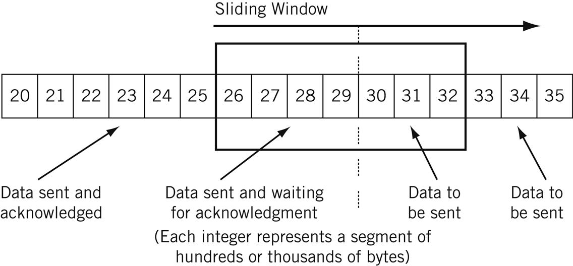
How do the windows work during a TCP connection? TCP forms its segments in memory sequentially, based on segment size, each needing only a set of headers to be added for transmission inside a frame. A conceptual “window” (it’s all really done with pointers) overlays this set of data, and two moveable boundaries are established in this series of segments to form three types of data. There are segments waiting to be transmitted, segments sent and waiting for an acknowledgment, and segments that have been sent and acknowledged (but have not been purged from the buffer).
As acknowledgments are received, the window “slides” along, which is why the process is commonly called a “sliding window.”
Figure 12.5 shows how the sender’s sliding window is used for flow control. (There is another at the receiver, of course.) Here the segments just have numbers, but each integer represents a whole 512, 1460, or whatever size segment. In this example, segments 20 through 25 have been sent and acknowledged, 26 through 29 have been sent but not acknowledged, and segments 30 through 35 are waiting to be sent. The send buffer is therefore 15 segments wide, and new segments replace the oldest as the buffer wraps.
Flow Control and Congestion Control
When flow control is used as a form of congestion control for the whole network, the network nodes themselves are the “receivers” and try to limit the amount of data that senders dump into the network.
But now there is a problem. How can routers tell the hosts using TCP (which is an end-to-end protocol) that there is congestion on the network? Routers are not supposed to play around with the TCP headers in transit packets (routers have enough to do), but they are allowed to play around with IP headers (and often have to).
Routers know when a network is congested (they are the first to know), so they can easily flip some bits in the IPv4 and IPv6 headers of the packets they route. These bits are in the TOS (IPv4) and Flow (IPv6) fields, and the hosts can read these bits and react to them by adjusting windows when necessary.
RFC 3168 establishes support for these bits in the IP and TCP headers. However, support for explicit congestion notification in TCP and IP routers is not mandatory, but common in many data center and cloud computing implementations today. Congestion in routers is usually indicated by dropped packets.
Performance Algorithms
By now, it should be apparent that TCP is not an easy protocol to explore and understand. This complexity of TCP is easy enough to understand: The underlying network should be fast and simple, IP transport should be fast and simple as well, but unless every application builds in complex mechanisms to ensure smooth data flow across the network, the complexity of networking must be added to TCP. This is just as well, as the data transfer concern is end to end, and TCP is the host-to-host layer, the last bastion of the network shielding the application from network operations.
To look at it another way, if physical networks and IP routers had to do all that the TCP layer of the protocol stack does, the network would be overwhelmed. Routers would be overwhelmed by the amount of state information that they would need to carry, so we delegate carrying that state information to the hosts. Of course, applications are many, and each one shouldn’t have to duplicate it all. So TCP does it. By the way, this consistent evolution away from “dumb terminal on a smart network” like X.25 to “smart host on a dumb network” like TCP/IP is characteristic of the biggest changes in networking over the years.
This chapter has covered only the basics, and TCP has been enhanced over the years with many algorithms to improve the performance of TCP in particular and the network in general. ECN is only one of them. Several others exist and will only be mentioned here and not investigated in depth.
Delayed ACK—TCP is allowed to wait before sending an ACK. This cuts down on the number of “stand-alone” ACKs, and lets a host wait for outgoing data to “piggyback” an acknowledgment onto. Most implementations use a 200-ms wait time.
Slow Start—Regardless of the receive window, a host computes a second congestion window that starts off at one segment. After each ACK, this window doubles in size until it matches the number of segments in the “regular” window. This prevents senders from swamping receivers with data at the start of a connection (although it’s not really very slow at all).
Defeating Silly Window Syndrome Early—TCP implementations processed receive buffer data slowly, but received segments with large chunks of data. Receivers then shrunk the window as if this “chunk” were normal. So windows often shrunk to next to nothing and remained here. Receivers can “lie” to prevent this, and senders can implement the Nagle algorithm to prevent the sending of small segments, even if PUSHed. (Applications that naturally generate small segments, such as a remote login, can turn this behavior off.)
Scaling for Large Delay-Bandwidth Network Links—The TCP window-scale option can be used to count more than 4 billion or so bytes before the sequence number field wraps. A timestamp option sent in the SYN message helps also. Scaling is sometimes needed because the Window field in the TCP header is 16 bits long, so the maximum window size is normally 64 kbytes. Larger windows are needed for large-delay times, high-bandwidth product links (such as the “long fat pipes” of satellite links). The scaling uses 3 bytes: 1 for type (scaling), 1 for length (number of bytes), and 2 for a shift value called S. The shift value provides a binary scaling factor to be applied to the usual value in the Window field. Scaling shifts the window field value S bits to the left to determine the actual window size to use.
Adjusting Resend Timeouts Based on Measured RTT—How long should a sender wait for an ACK before resending a segment? If the resend timeout is too short, resends might clutter up a network slow in relaying ACKs because it is teetering on the edge of congestion. If it is too long, it limits throughput and slows recovery. And a value just right for TCP connection over the local LAN might be much too short for connections around the globe over the Internet. TCP adjusts its value for changing network conditions and link speeds in a rational fashion based on measured RTT, how fast the RTT has change in the past.
TCP Behaving Badly?
TCP has long been the object of concern in TCP/IP networks. As soon as the Web came along in the early 1990s, behavior that had been merely annoying now become critical. For real-time, request-and-response queries, the reliability that characterized TCP came at the price of decreased speed. In other words, TCP was s-l-o-w due to connection overhead and error recovery.
Many ISPs began to cache commonly accessed Web pages at strategic places in their networks in order to serve them up quicker. However, this practice violated the end-to-end features of TCP, where a client was supposed to fetch a page from a server and not a cached (and possibly obsolete) copy of a page. This began a movement to “reform” and modify TCP that continues today. If anything, the ubiquitous nature of the Internet has only intensified this pressure.
One of the most important developments in networking today is the rise of the data center. It used to be (and not too long ago) that when people went on vacation, they called a travel agent. When they wanted to watch a movie, they went to a movie theater (often the only air conditioned place in town). If they wanted to watch television, the family sat together in their living room. If they wanted to buy a book, they went to the book store. If they wanted to shop, they went out to go shopping. Now all these activities, and many more like playing video games and gambling, are accomplished by using a client computer to access a server somewhere.
This means that the companies that supply goods and services over the Internet are constantly collecting data about their customer base. This information is used to focus marketing efforts, sales collateral, and product development and placements strategies. The data center is becoming the key technology for modern businesses of all shapes and sizes, from direct-to-consumer to business-to-business applications.
This is not the place to explore the rise and structure of massive data centers. This book is about TCP/IP. It is enough to note a few overall structural characteristics of these data centers and show why TCP is often a problem in their operation.
The real heart of the issue is related to the time value of information. All information has value, of course, but some information has a value that rapidly diminishes to zero as soon as everyone knows it. Once, all the world’s stock exchanges operated independently, based on local opening and closing times. By the 1950s, corporations were global and so were communications (at least for voice) and financial markets could exploit knowing the closing price in one market before the opening of another. There was even a movie made in 1961 called Five Golden Hours that explored the advantages of knowing the closing price in Rome before the opening of the stock market in New York five “golden” hours later.
What was then true of financial markets is now true of almost everything. We live in world where, if I know something a crucial five minutes before you do, I will make a million dollars and you will lose a million. Automatic trading algorithms based on AI often convert this margin to seconds or even fractions of a second.
But let’s consider a more pedestrian example. You operate a multi-national corporation that sells goods over the Internet on three continents. You have data centers gathering customer orders and information in three large data centers. The servers are mounted in large racks with a switch at the top called, naturally, a top of rack (TOR) switch. These connect to other switches in what is called a “leaf and spine” topology (we’ll talk more about these “CLOS networks” in the chapter on new uses for BGP). Because of the distributed nature of the data, the querying client could be inside the data center itself, finding out or sharing what it knows with other servers using TCP/IP.
Databases in these data centers often use NoSQL (for “Not Only SQL”) for updates and queries. Online customers are notoriously lax about entering complete information about zip codes or middle names or telephone numbers. Entries are often incomplete, but as long as you can take an order, you’ll consider the entries sufficient, even if they are duplicates (as happens when a customer fills out the “new customer” form twice). NoSQL does not care if the database is perfect, as long as it is functional.
You would like to know where your customers live. Are they in rural areas, small towns, cities, or megalopolises? This data could determine resources for factory locations, marketing efforts, sales offices, and be useful for a myriad of other business purposes. But I need to know NOW.
Modern networks use a “scatter-gather” technique to distribute the query to multiple data centers and the multiple servers in the racks that hold the information. (We’ll say more about this movement to cloud computing and virtualized services later, but for now, this does not matter.) Once I have partial results, I quickly process the gathered information and distill an answer for you: 30% rural, 20% small towns, 15% cities and 35% in large metropolitan areas.
Why is TCP such a bad fit for this world? Well, if TCP connections are required for each scatter-gather communication and query, the enormous handshake overhead of TCP becomes a bottleneck. If one server in one rack holds crucial information, all of the NoSQL queries tend to pile onto one destination server, causing congestion in the leaf-and-spine network. And every segment dropped must be resent and sequenced correctly. This traffic creates “TCP in-cast storms” that can bring a whole data center to its knees.
So TCP is constantly being adjusted for modern data center use. We’ve already seen one adaptation that is essential for modern data center use of TCP: ECN. We’ll meet others in the chapter on cloud computing.
TCP and FTP
First we’ll use a Windows FTP utility on wincli2 (10.10.12.222) to grab the 30,000-byte file test.stuff from the server bsdserver (10.10.12.77) and capture the TCP (and FTP) packets with Wireshark. Both hosts are on the same LAN segment, so the process should be quick and error-free.
The session took a total of 91 packets, but most of those were for the FTP data transfer itself. The Ethereal statistics of the sessions note that it took about 55 seconds from first packet to last (much of which was “operator think time”), making the average about 1.6 packets per second. A total of 36,000 bytes were sent back and forth, which sounds like a lot of overhead, but it was a small file. The throughput on the 100 Mbps LAN2 was about 5,200 bits per second, showing why networks with humans at the controls have to be working very hard to fill up even a modestly fast LAN.
We’ve seen the Wireshark screen enough to just look at the data in the screen shots. And Wireshark lets us expand all packets and create a PDF out of the capture file. This in turn makes it easy to cut-and-paste exactly what needs to be shown in a single figure instead of many.
For example, let’s look at the TCP three-way handshake that begins the session in Figure 12.6.
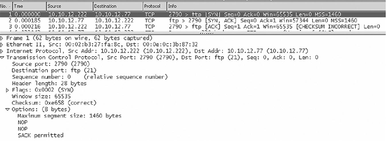
The first frame, from 10.10.12.222 to 10.10.12.77, is detailed in the figure. The window size is 65,535, the MSS is 1460 bytes (as expected for Ethernet), and selective acknowledgments (SACK) are permitted. The server’s receive window size is 57,344 bytes. Figure 12.7 shows the relevant TCP header values from the capture for the initial connection setup (which is the FTP control connection).
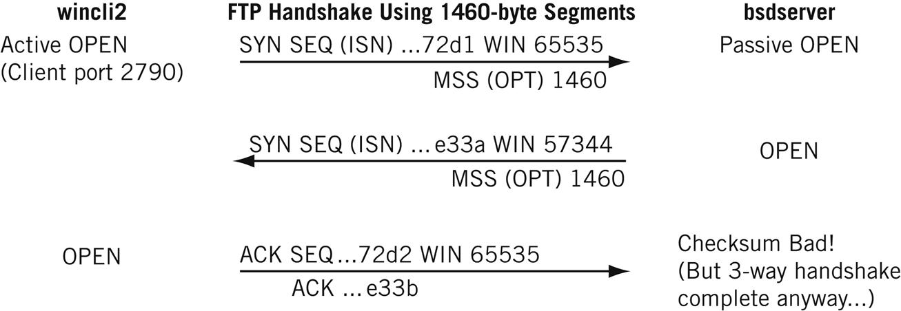
Wireshark shows “relative” sequence and acknowledgment numbers, and these always start at 0. But the figure shows the last bits of the actual hexadecimal values, showing how the acknowledgment increments the value in sequence and acknowledgment number (the number increments from 0x…E33A to 0x…E33B), even though no data have been sent.
This older version of Windows uses 2790 as a dynamic port number, which is really in the registered port range and technically should not be used for this purpose.
This example is actually a good study in what can happen when “cross-platform” TCP sessions occur, which is often. Several segments have bad TCP checksums. Since we are on the same LAN segment, and the frame and packet passed error checks correctly, this is probably a quirk of TCP pseudo-header computation and no bits were changed on the network. There is no ICMP message because TCP is above the IP layer. Note that the application just sort of shrugs and keeps right on going (which happens not once, but several times during the transfer). Things like this “non–error error” happen all the time in the real world of networking.
At the end of the session, there are really two “connections” between wincli2 and bsdserver. The FTP session rides on top of the TCP connection. Usually, the FTP session is ended by typing BYE or QUIT on the client. But the graphical package lets the user just click a disconnect button, and takes the TCP connection down without ending the FTP session first. The FTP server objects to this breach of protocol and the FTP server process sends a message with the text, You could at least say goodbye, to the client. (No one will see it, but presumably the server feels better.)
TCP sessions do not have to be complex. Some are extremely simple. For example, the common TCP/IP “echo” utility can use UDP or TCP. With UDP, an echo is a simple exchange of two segments, the request and reply. In TCP, the exchange is a 10-packet sequence.
This is shown in Figure 12.8, which captures the echo “TESTstring” from lnxclient to lnxserver. It includes the initial ARP request and response to find the server.
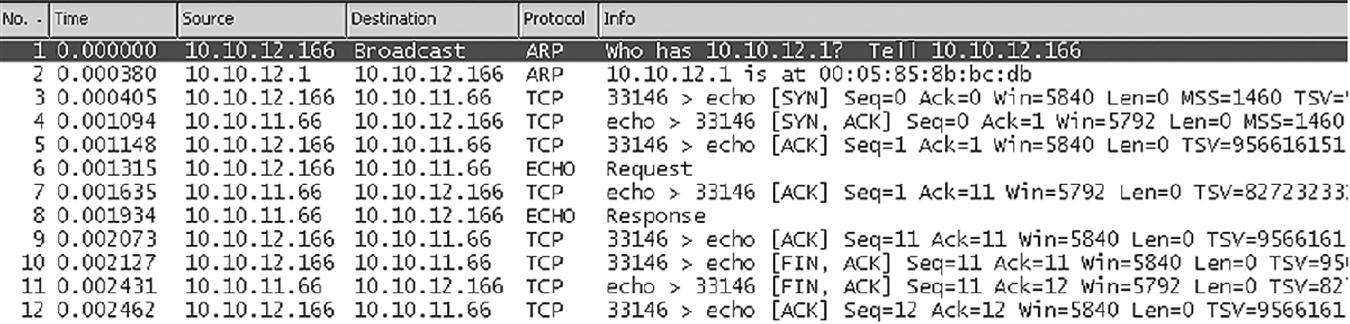
Why so many packets? Here’s what happens during the sequence.
Handshake (packets 3 to 5)—The utility uses dynamic port 33,146, meaning Linux is probably up-to-date on port assignments. The connection has a window of 5840 bytes, much smaller than the FreeBSD and Windows XP window sizes. The MMS is 1460, and the exchange has a rich set of TCP options, including timestamps (TSV) and windows scaling (not used, and not shown in the figure).
Transfer (packets 6 to 9)—Note that each ECHO message, request and response, is acknowledged. Ethereal shows relative acknowledgment numbers, so ACK=11 means that 10 bytes are being ACKed (the actual number is 0x0A8DA551, or 177,055,057 in decimal.
Disconnect (packets 10 to 12)—A typical three-way “sign-off” is used.
We’ll see later in the book that most of the common applications implemented on the Internet use TCP for its sequencing and resending features.
Questions for Readers
Figure 12.9 shows some of the concepts discussed in this chapter and can be used to help you answer the following questions.
1. What are the three phases of connection-oriented communications?
2. Which fields are present in the TCP header but absent in UDP? Why are they not needed in UDP?
3. What is the TCP flow control mechanism called?
4. What does it mean when the initial sequence and acknowledgment numbers are “relative”?
5. What is the silly window syndrome? What is the Nagle algorithm?
