MPLS-Based Virtual Private Networks
Abstract
In this chapter, you will learn one type of virtual private network architecture: the MPLS-based VPN, and in particular, a Layer 2 VPN (L2VPN). We’ll also briefly look at using PPTP over DSL for remote access, another type of arrangement that is often considered a VPN.
You will learn how an L2VPN can make CE1 and CE2 appear to be connected by a single LAN, creating a virtual private LAN service (VPLS) between them. We’ll also configure a complete VPLS based on L2VPNs.
Keywords
L2VPN; BGP/MPLS VPNs; DDOS; PPTP; CHAP; L2TP network server; L2TP access concentrator
In this chapter, you will learn one type of virtual private network architecture: the MPLS-based VPN, and in particular, a Layer 2 VPN (L2VPN). We’ll also briefly look at using PPTP over DSL for remote access, another type of arrangement that is often considered a VPN.
You will learn how an L2VPN can make CE1 and CE2 appear to be connected by a single LAN, creating a virtual private LAN service (VPLS) between them. We’ll also configure a complete VPLS based on L2VPNs.
In Chapter 19 on Internet Protocol (IP) switching, we introduced the idea of Multiprotocol Label Switching (MPLS) and configured a static label-switched path (LSP). That chapter showed how the LSP could be used for traffic engineering (TE) to steer transit traffic away from the least-cost hops traversed by local traffic. This chapter builds on those concepts and explores the security provided by one type of Virtual Private Network (VPN) Protocol, the Point-to-Point Tunneling Protocol (PPTP), and one type of VPN architecture, the MPLS-based VPN.
This chapter creates an L2VPN supporting VPLS. It does not create what is known as an L3VPN or BGP/MPLS IP VPN, which is actually more common. There are a few reasons we will describe an L3VPN but not configure it. Many introductions to VPNs start with L2VPNs before moving on the more complex L3VPNs. In addition, there is are much more complete book written about BGP/MPLS VPNs available. We urge all interested readers to obtain one of those books after completing this one.
This chapter deals with more general aspects of security (and privacy) on the Internet, as companies, individuals, and government organizations blend increasingly sensitive traffic onto a single global public network. PPTP allows workers in home offices to access remote corporate resources such as servers and files over a public ISP’s unsecure network. MPLS-based VPNs allow ISP to offer “private” (virtually private) networks to customers, while maintaining the global reachabilty and universal connectivity that Internet users have come to take for granted.
Before we build an L2VPN for LAN1 and LAN2, let’s take a quick look at remote access using PPTP while employing a popular adjunct device, the RSA SecureID. That’s how we access the Illustrated Network from the comfort of our home offices.
So, we’re really doing two types of VPN at once in this chapter (as shown in Figure 20.1). Both the home DSL link and the routers are highlighted, because this is where we’ll be building our VPNs (we’ll route LAN1 to LAN2 traffic away from the links to the Internet on P4 and P2). Another change is necessary (one we’ve seen before), and this time the change will be in effect through the end of the book. Ace and Best ISPs have merged to become Best-Ace ISP, and the network now has only one AS number (65527). This will simplify the configurations used in the rest of the book, starting with our MPLS-based VPN.


PPTP for Privacy
The RSA SecurID that one is issued for remote access to the corporate network requires one to copy the six random numbers that appear on its screen at log-in. There’s also a four-digit static prefix that does not change, but the last six digits change every 30 seconds. This has been challenging for some users, who cannot copy the digits correctly and exceed their retry count (usually three). After that, the account is locked until an administrator releases it. Newer SecurID tokens plug right into the USB port of the computer or run on the computer itself, so no typing is required.
Even though our home office access is using PPP over DSL, the PPTP connection still has to send the PPP and PPTP control messages to the corporate network device, the L2TP Access Concentrator (LAC). (We’ll talk about the relationship between PPTP and L2TP later.) These messages indicate that a connection request is being made with the PPP Link Control Protocol (LCP). The packet exchange at the beginning of the connection is shown in Figure 20.2. The actual data are sent inside packets formatted according to the generic routing encapsulation (GRE) method, which basically adds another IP header to the existing one.

For the first time in this book, this Wireshark capture file has been edited to substitute the actual addresses used for “Martian” addresses for reasons of security. The client PC is using 169.254.99.1 and the server is using 250.99.111.4.
The first GRE packet does not come until packet 20. In fact, there are many more compressed PPP packets than those using GRE. Figure 20.3 shows this relationship in the packet sequence taken from later in the same session. We’ll talk more about these PPP and GRE packets later in this chapter.

Types of VPNs
A VPN is a private communications network most often used within a single organization to communicate over a public network. VPN traffic is carried over a public network infrastructure, such as the Internet, using standard and unsecure protocols. However, the VPN mechanisms make the network look and feel like a private network composed of network nodes owned and operated by the organization and the leased lines connecting them, which carry the organization’s traffic only.
In truth, the “private” network was never really as private as customers thought. Carriers did a good marketing job, but in fact every customer’s bits were freely mixed on high-bit-rate backbones, although users could not tell whether this was the case. But when a massive microwave link was compromised in some way, hundreds or thousands of customers’ data were at risk. Once the carriers all became ISPs, the marketing material for private circuits was retooled to support the use of virtual circuits over the public network.
Chapter 19, which covered MPLS, mentioned the idea of a virtual circuit (or channel or connection) as something that is “not really a private circuit/channel/connection, but acts just like one,” at least as far as the customer is concerned. This chapter extends that concept into the general area of VPNs.
The chapter on MPLS introduced the idea of using MPLS LSP “tunnels” as the basis for a VPN, because MPLS LSPs are pretty much invisible to IP hackers on the network. This chapter elaborates on that idea.
Security and VPNs
On modern networks, a firewall of some type is used as a security device and sits between clients and servers. The firewall can pass authentication data to an authentication service for the local network, such as RADIUS. A trusted person with privileged access (such as root, often only using trusted devices that are physically secure) is allowed to access resources not available to general users, such as the routers and the firewall itself.
We’ll talk more about firewalls in Chapter 32. For now, we’ll just mention them and note that VPNs can use firewalls, and indeed they can be built up from firewalls but don’t have to be. For many people, any type of VPN implies the purchase and use of specialized devices that form the endpoints of the VPN. To these users, the VPN is created by the customer; in brief, it is not offered as a service by the ISP. The exception, of course, is MPLS-based VPNs, which we will explore in this chapter.
VPNs do not have to be secure. An organization that uses MPLS to create the appearance of the virtual-circuit, network-like frame relay or ATM might call the result a VPN, but this is not really more secure than any other type of network. Secure VPNs use encrypted tunneling protocols to add confidentiality (a counter-sniffing notion), user and resource authentication (to prevent spoofing), and message integrity (to detect message alteration) to achieve the levels of security and privacy desired (or affordable).
No current network is entirely protected against hackers and some simple Internet attacks, such as distributed denial-of-service (DDOS) attacks, are still painfully effective. What network security seeks to do is raise the work factor for the bad guys to the point where it takes so long to break the code that the information is useless and it’s easier to attack another network whose administrators are less diligent in security areas.
If this sounds too defeatist, consider the fact that Kevin Mitnick (a hacker guru) admitted in his book, The Art of Intrusion, that most of his exploits relied on manipulating people (“social engineering”) and not frontal attacks on equipment and software (“I’m with security. We have to change your password. What is it again?”). A lot of security dollars are spent protecting users from themselves.
VPNs and Protocols
There are several types of VPNs that can be built, and the choice of which type to use is not trivial. Many VPN schemes have a lot to do with security. But secure VPN technologies can be the basis for a security overlay and used to enhance security on the network.
We’ll just talk generally about all types of VPNs, create an MPLS-based VPN on the Illustrated Network at the end of the chapter, and consider ways to “harden” it in the section on security. All VPNs are in some sense “trusted” more than simple IP router networks. Secure VPN protocols include the following:
IPSec (IP security)—IPSec has been aptly described as “a piece of IPv6 that fell into IPv4.” A mandatory part of IPv6, IPSec was rushed into the IPv4 world as an advanced security measure.
SSL—SSL can be used to tunnel the entire network stack, as in the OpenVPN approach, or to create an SSL VPN to secure certain pieces of the network.
PPTP—A tunneling method developed by Microsoft for remote access to network resources through a special server.
L2F (Layer 2 forwarding)—Another secure remote-access method developed by Cisco.
L2TP (Layer 2 tunneling protocol)—A sort of “compromise” method that includes contributions by both Cisco and Microsoft. Today, L2TP has pretty much replaced L2F.
VPNs do not rely on one protocol or another for everything. For example, networks dominated by Windows software generally use VPNs that employ PPTP and L2TP (along with IPsec) to construct a secure VPN.
We’ve already talked about SSL, and IPSec is covered (and featured) in a later chapter. Let’s take a look at PPTP and L2TP methods, which are for securing intermittent remote user access through dial-up links or (increasingly) from home offices over DSL.
PPTP
PPTP was developed by Microsoft as an extension to PPP and is now defined in RFC 2637 (with errata). It is a Layer 2 tunneling protocol, meaning that the payload is the Layer 2 frame itself, encrypted and preceded by a small PPTP header based on extensions to the generic routing encapsulation (GRE) header described in RFC 2784. This frame, with header and trailer, is placed inside another packet and sent over the network between what PPTP calls a PPTP access concentrator (PAC) and a PPTP network server (PNS).
PPTP is a client/server protocol with the PAC as the client and the PNS as the server. Control messages are exchanged over TCP port 1723. Encryption is provided by underlying PPP mechanisms. Encryption keys are generated from the authentication process, which normally uses the Challenge Handshake Authentication Protocol (CHAP)—a three-way handshake using encrypted passwords (defined in RFC 1994).
In PPTP, PPP uses compressed data, which is not a form of encryption but does present an obstacle to unsophisticated hackers who only dabble in eavesdropping. The GRE encapsulated data are secure. PPTP is still widely used today, often in conjunction with some type of user authentication token such as an RSA SecurID numerical pass-code generator. Users dial in to the PAC and log in using the passcode, which changes every 30 seconds. Dial-in connections are usually very secure because they can follow any path over the PSTN and use any PAC port available. PPTP covers communication between the PAC (which might be supporting traveling sales agents on the east coast) and the main network with the PNS (which might be on the west coast). In addition to controlling costs, PPTP used this way can use a VPN setup for that purpose.
Today, home workers with DSL often use PPTP to tunnel through the ISP’s unsecure network to reach the relative security of the organization’s more protective environment. Additional security is needed to reach the PAC from the user location. Between PAC and PNS, a VPN tunnel itself can be built using double encryption; that is, taking the PPTP data and encrypting it once again. It all depends on how paranoid the organization is (as the doomed Kurt Cobain noted, just because you’re paranoid doesn’t mean they’re not out to get you).
L2TP
Cisco first used their L2F as an alternative to Microsoft’s PPTP. But eventually both companies combined the best of both worlds to produce L2TP, a more flexible version of PPTP. L2TP is also a way to send encrypted frames between client and server over the Internet, and again the client is a remote access point and the server on a protected network. In L2TP, these are now the L2TP access concentrator (LAC) and L2TP network server (LNS).
L2TP is designed to work with more than dial-in users seeking Internet connectivity. The LAC and LNS can be linked not only over the Internet but over frame relay and ATM networks (L2TP calls them “non-IP WAN technologies”). A special L2TP device, the LAC client, can attach to the LNS directly without going through the dial-in LAC device. The overall architecture is shown in Figure 20.4.
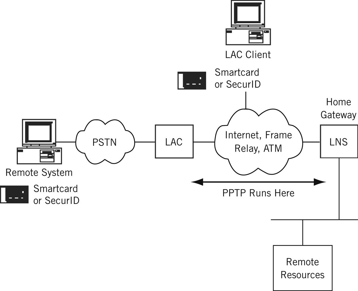
Encryption in L2TP is provided with IPSec (why always reinvent the wheel?). There is a two-step L2TP encapsulation. An initial L2TP frame encapsulation with PPP is used to build a new IP packet using UDP port 1701 on the server side and an L2TP header. This step is followed by the IPSec encapsulation. Although it is technically allowed to send L2TP data without this step, it defeats the purpose. L2TP is defined in RFC 2661 (with errata).
PPTP and L2TP Compared
There are many differences between PPTP and L2TP, but the following comprise the main ones.
• PPTP cannot support a non-IP network directly, whereas L2TP works with any network that can provide point-to-point connectivity.
• PPTP supports only a single tunnel from client to server, whereas L2TP can support multiple tunnels—perhaps used as part of a multilevel security and QoS scheme.
• PPTP does not support header compression, whereas L2TP can compress its header for efficiency purposes.
Nevertheless, PPTP remains more popular than L2TP, and organizations that support many remote users (traveling or at home) with Windows-based laptops or PCs generally still use PPTP. The main alternative to PPTP and L2TP to add security to a VPN connecting an organization’s sites is IPSec. IPSec is discussed in the next chapter.
Types of MPLS-Based VPNS
Now that MPLS and security protocols have been defined, let’s look at the types of VPNs that can be built from these pieces. There are two major types of VPN: Those that operate at Layer 3 (the same layer as the routers that make up the network), and those that operate at Layer 2, the level of LANs linked over the VPN.
Which is “better”? There is no easy answer, and even the question should be framed more clearly in terms of what is meant by “better.” Better in terms of cost, complexity (or simplicity), cryptographic sophistication, or something else altogether?
This section describes the major characteristics of each and configures one type on the Illustrated Network, not as an endorsement, but just as an example. The often bewildering terminology applied to VPN types has now been standardized in RFC 4364 (with errata) and updated by RFC 4577, RFC 4684, and RFC 5462.
Layer 3 VPNs
Consider an organization with two widely separated sites with LANs running the TCP/IP protocol suite and using all of the techniques and applications we’ve described earlier in this book. What would a totally private IP network connecting the two sites look like? Well, the organization could contract with a carrier for a long link connecting the sites and install customer routers at each location. Security is provided by the isolated nature of the traffic on the leased private line (although that isolation is rarely absolute, as has been pointed out) and restricted access at the sites themselves. There is no Internet access, of course, unless a separate router or port is provided for this purpose.
But many carriers have evolved beyond the stage of mere “bandwidth mongers” and want to provide more sophisticated services as ISPs. Private lines are usually paid for by the mile as well as by bandwidth, and the bandwidth use for bursty IP applications is wildly erratic and thus wasted much of the time. Private networks are designed for peak loads, such as end-of-month or end-of-quarter frenzies, and sit idle most of the time. The PSTN is no exception, by the way, and is designed (in the United States) for the 5 days of maximum calling volume: Mother’s Day, Christmas, New Year’s Day, Thanksgiving, and Father’s Day. Only unpredictable major disasters can swamp the PSTN at other times.
Adding sites can be a problem in this scenario. Organizations with many sites can always contract floor space at some central point and install their own routers and leased lines there in a hub configuration instead of a mesh to cut down on point-to-point mileage costs and the number of ports required on each router.
Of course, the isolation of the private network is always attractive to customers. But what if the ISP can promise a network that looks like the rented-floor-space router hub solution with leased private line connectivity? In other words, the ISP provides a solution that looks like a private router network to the customer—complete with what appear to be dedicated links and routers that contain routing information for that customer and that customer only. This is, of course, a VPN.
But what we have described is not just any type of VPN—it’s a Layer 3 VPN (L3VPN) because the virtual nature of the network is apparent at Layer 3 (the IP layer). It’s really a network of virtual routers because in reality the ISP is selling the same router resources to hundreds and even thousands of customers if the router and links are hefty enough to handle the loads. The different L3VPN customers cannot see each other at all, or even communicate unless special arrangements are made (this is sometimes called an “extranet,” the closed VPN being an “intranet”). Each can only see the information in its own virtual routing and forwarding (VRF) tables, as if the router were divided into many tiny logical pieces.
L3VPNs are one of the most complicated entities that can be set up on a router network. They are built on MPLS LSPs, as might be expected, and carefully distribute routing information only to the VRFs that should receive it. (There is still a “master” routing table that receives all routing information: Someone has to run the L3VPN itself.)
Basic L3VPN connectivity is bad enough. It is much worse when multicast capabilities must be added to the tunnels, which are essentially point-to-point connections that do not easily replicate packets.
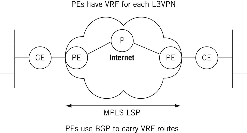
The RFCs and drafts for L3VPNs, which are numerous, use MPLS and BGP as the foundations for these types of VPNs—also called PPVPNs (provider-provisioned VPNs). They also introduce a distinctive architecture and terminology, as shown in Figure 20.5. The figure shows a simple two-site arrangement, but the same terms apply to more complicated configurations.
Customer Edge
Each site has a customer-edge (CE) router, designated CE1, CE2, … CEn as needed. These routers are owned and operated by the customer and are at the “edge” of the VPN. At least one link runs to the ISP and carries customer data to and from the ISP’s network. The data on the link can be in plain text (the link is generally short, point to point, and not considered a high security risk) or encrypted with IPSec, SSL, or some other VPN protocol. The CEs still run a routing protocol, but only to gather information about other CE routers belonging to their own L3VPN.
Provider Edge
Each customer site connects to a provider-edge (PE) router, designated PE1, PE2, … PEn as necessary. These are owned and operated by the ISP and are at the provider “edge” of the VPN. A PE router can carry traffic to and from many CE routers, and even carry “regular” Internet traffic for other customers. These are routers with the VRFs and run MPLS to the other PE routers and BGP to carry customer routing information. In MPLS terms, these are the ingress and egress routers, but a PE router on one VPN can be a transit (P) router on another.
Provider
The provider (P) routers are the MPLS transit routers that carry VPN traffic through the provider “core” or backbone. As in MPLS, there must be at least one P router, but there are usually quite a few, depending on the popularity of the L3VPN service. As with PE routers, the P routers can carry general ISP traffic that has nothing to do with VPNs. MPLS LSPs connect the PE routers through the P routers, and BGP is used with route distinguishers to ensure that routing updates go into the proper VRFs.
The routing tables on the CE routers are generally quite simple. They contain just a few routes to the other CE router sites and a default for generic Internet access, which might be through a separate router or through the VPN itself (one tunnel leads to an Internet router “gateway”). If the Internet access (few VPNs can afford to cut themselves off from the Internet entirely) is on another router at the customer site, a firewall is typically used to protect this “back door” to the VPN. Firewalls are discussed in a later chapter.
Layer 2 VPNs
In an L3VPN, the two CE routers are still on two separate networks—just like LAN1 and LAN2 on the Illustrated Network. CE0 and CE6 use different IP network addresses, such as 10.0.50.2/24 and 10.0.16.2/24, on their links to PE5 and PE1 toward the network backbone.
LANs are Layer 2 constructs at heart. Ethernet frames only care about MAC layer addresses, not IP addresses. Why not just build the VPN at Layer 2 and connect the two CE routers into one big “virtual” LAN that seems to be as private as both LANs would be separately? This is the idea behind an L2VPN.
Even though an L2VPN service is delivered over an ISP’s collection of routers (just like an L3VPN), the end result is much simpler than an L3VPN. This is because there is no need to maintain separate virtual routing information for each customer. Both customer routers can use one IP address space (perhaps 10.99.99.0/24), and do not need to run a routing protocol between the CE routers at all because they appear to be directly connected and at opposite ends of the same “link.”
The L2VPN architecture still uses the CE-PE-P terminology and uses MPLS LSPs, but the basic content of the tunnels are Ethernet frames (other “emulated” LANs are sometimes supported). The backbone routers in an L2VPN are essentially transformed into LAN bridges. The VPLS tables on the PE routers are now long lists of MAC layer addresses more similar to ARP caches than to routing tables.
L2VPN service offerings have a variety of names. A popular offering from many ISPs is some form of virtual private LAN service (VPLS). The LANs are now virtual LANs (VLANs), and the Ethernet frames between CE and PE routers must employ VLAN tagging to allow the ISP to tell the frames apart at Layer 2. The PE routers are configured with a VPLS virtual port that forms the endpoint of the MPLS tunnel (LSP) that carries the frames from one LAN to the other.
There are many other variations on the basic VPN types described here. RFC 4026 lists (in addition to L3VPNs, L2VPNs, and VPLS) seven other types of VPN, mostly variations on the L2VPN theme.
• Virtual Private Wire Service (VPWS)
• IP-only LAN-like Service (IPLS)
Why all the interest in linking CE routers over Layer 2 through an ISP’s router network? The trend today is to extend Ethernet’s reach and speed to incredible distances (about 25 miles) and bandwidths (100 Gbps or more). Some see Ethernet as the ultimate “universal” network, and one without all the risks inherent in IP-based router networks. How many malicious users are busily crafting phony Ethernet frames?
Of course, malicious users followed networking from the PSTN (where they were first active in securing free long-distance service) onto the Internet, and there is no reason to think they won’t follow the action anywhere else. But VPNs and virtual LANs are at least prepared to address security issues from the start.
VPLS: an MPLS-Based L2VPN
To make a good configuration for VPLS, we’ll have to get a little creative with our network. The two routers attached to LAN1 and LAN2, customer-edge routers CE1 and CE2, will now support VLAN tagging (not difficult to do). With VPLS configured, both LANs still use addresses 10.10.11.0/24 and 10.10.12.0/24. (In other words, we’ll start the VPLS at the ISP, not at the customer routers—not all users want to renumber all of their IP devices.)
But now it will look like the CE routers are directly connected with a gigabit Ethernet LAN sharing a common IP network address. In this example, that address is 10.99.99.0/24 (which should be distinctive enough to easily pick out). So, this is where the “virtual LAN” comes in—on the link between CE1 and CE2. We’ve also merged Best-Ace ISP into one AS (the number is not important) so that we can use IBGP to distribute the routes and avoid more complex configurations.
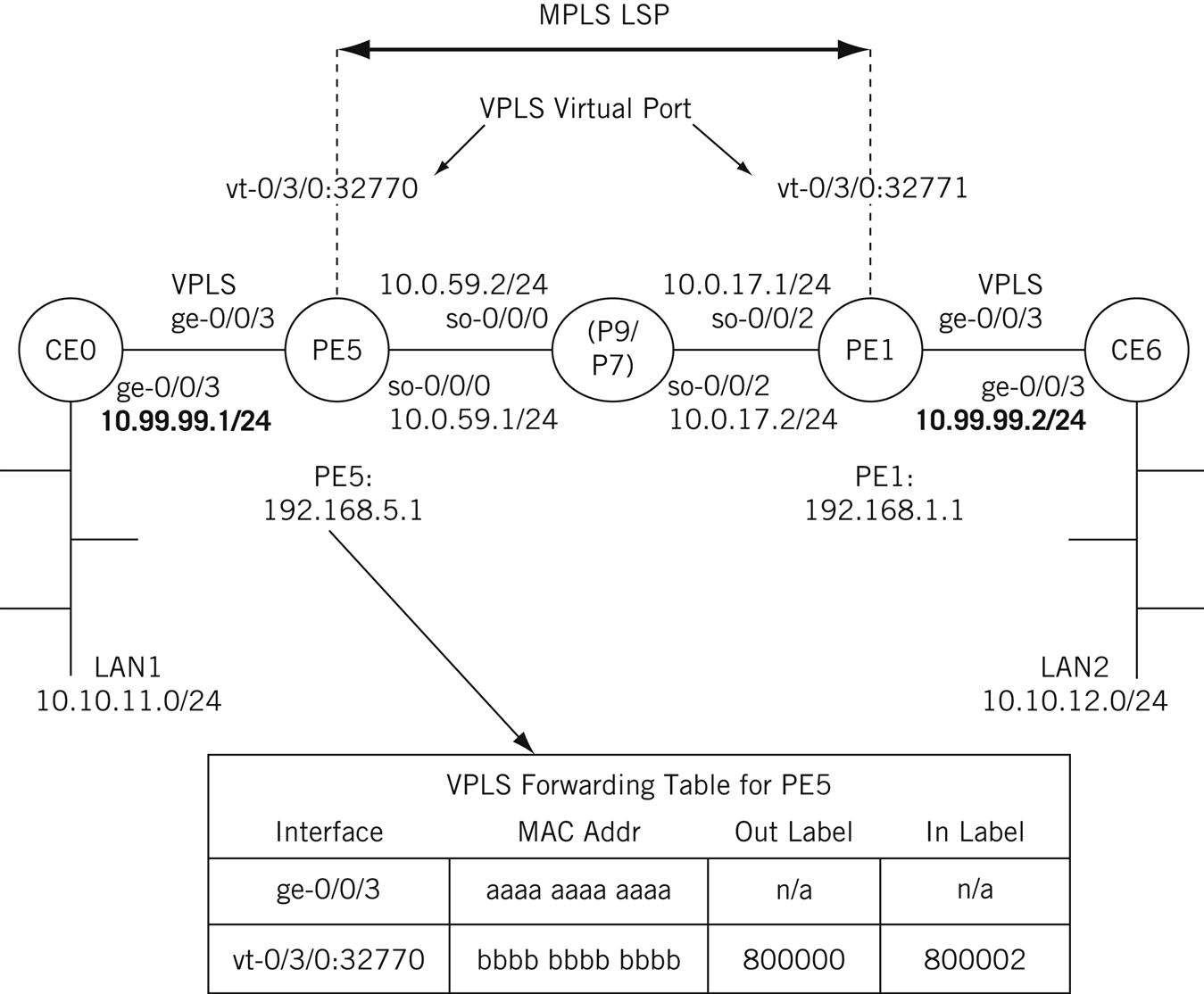
The simplified Illustrated Network configuration for VPLS, along with interface designations and IP addresses, is shown in Figure 20.6. The figure also shows an example of the VPLS table on router PE1. This table shows how the MAC addresses on the interfaces to the CE routers map to MPLS labels instead of IP addresses, as in an L3VPN.

The VPLS virtual port interfaces on PE1 and PE2 are designated with the vt-(virtual tunnel) prefix. These are not physical interfaces on the routers, of course, but logical interfaces that form the endpoints of the MPLS LSP connecting the routers over the ISP core backbone. This interface is not configured directly, but is the result of the VPLS configuration steps.
Router-by-Router VPLS Configuration
Let’s look at each router individually and show the sections of the configuration files that directly create the VPLS service between LAN1 and LAN2. Keep in mind that there is actually much more to the complete working configuration than just these statements.
CE0 Router
All that is needed on the CE0 router is the interface to the PE router and the VLAN identifier and IP address associated with it. These values must match the configuration on router CE0. (The LAN1 interface is still fe-1/3/0 and is still using 10.10.11.1/24.)
set interfaces ge-0/0/3 vlan-tagging;
set interfaces ge-0/0/3 unit 0 vlan-id 600; # the VLAN ID must must match throughout the configurations
set interfaces ge-0/0/3 unit 0 family inet address 10.99.99.1/24; # this address space must match the CE6 link address we use
PE5 Router
The PE router configurations are the most elaborate among the VPLS routers. These configurations are rather lengthy, so comments are used throughout. The PE routers need BGP, MPLS, OSPF, and RSVP to be configured properly for the LSP to work correctly. RSVP sets up the MPLS LSPs, OSPF handles routine routing chores, and BGP is used to carry the VPLS MAC layer information between the PE routers.
The PE routers also need to configure VLAN tagging and VPLS encapsulation on the interfaces (physical and logical) to the CE routers. The VLAN ID must match as well, but no IP address is needed for this “Layer 2” interface. There is a space between major sections of the configuration and liberal comments to help track what is being configured.
set interfaces ge-0/0/3 vlan-tagging; #interface to CE0
set interfaces ge-0/0/3 encapsulation vlan-vpls;
set interfaces ge-0/0/3 unit 0 encapsulation vlan-vpls;
set interfaces ge-0/0/3 unit 0 vlan-id 600; # must match across the network
set interfaces so-0/0/0 unit 0 family inet address 10.0.59.1; # interface to P9
set interfaces so-0/0/0 unit 0 family mpls;
set routing-options autonomous-system 65527;
set routing-options forwarding-table export exp-to-fwd; # used to distinguish VPLS "routes"
set protocols rsvp interface all; # turn on RSVP
set protocols mpls label-switched-path PE5-to-PE1 to 192.168.1.1; # The LSP to connect VPLS routers thru loopback addresses
set protocols mpls interface all;
set protocols bgp group vpls-pe type internal;
set protocols bgp group vpls-pe local-address 192.168.5.1;
set protocols bgp group vpls-pe family l2vpn unicast; # this VPLS is an L2VPN type and only cares about unicast traffic
set protocols bgp group vpls-pe neighbor 192.168.9.1; # IBGP peer router P9
set protocols bgp group vpls-pe neighbor 192.168.7.1; # IBGP peer router P7
set protocols bgp group vpls-pe neighbor 192.168.1.1; # IBGP peer router PE1
set protocols ospf traffic-engineering;
set protocols ospf area 0.0.0.0;
set protocols ospf interface all; # run OSPF to all routers
set policy-options policy-statement exp-to-fwd term A from community green-community;
# policy to load forwarding table – the community must also match
set policy-options policy-statement exp-to-fwd term A then install-nexthop lsp PE5-to-PE1;
# makes this LSP the next hop for the VPLS
set policy-options policy-statement exp-to-fwd term A then accept;
# accepts only community = green-community
set policy-options community green-community; # sets the community value on BGP routes for the VPLS
set routing-instances green instance-type vpls; # creates a special forwarding table for VPLS traffic
set routing-instances green interface fe-0/1/0.0;
set routing-instances green route-distinguisher 10.10.10.1;
set routing-instances green vrf-target target:11111:1;
# this value must match the community
set routing-instances green protocols vpls site-range 10; # this starts the main VPLS configuration
set routing-instances green protocols vpls site greenPE1 site-identifier 1; # after the protocols, communities, and the rest, this is simple…
P Router (P9)
The P routers still need the same BGP, MPLS, OSPF, and RSVP to become a transit router between PE5 and PE1. But at least no major policies need to be applied or tables created. The configuration shown, on P9, is mirrored by the one on P7 (which is not shown).
set interfaces so-0/0/1 unit 0 family inet address 10.0.79.2; # interface to P7
set interfaces so-0/0/1 unit 0 family mpls; #needed for the VPN
set interfaces so-0/0/2 unit 0 family inet address 10.0.59.2; # interface to PE5
set interfaces so-0/0/1 unit 0 family mpls; #needed for the VPN
set protocols rsvp interface all; # turn on RSVP for signaling
set protocols mpls interface all; # turn on MPLS for packet parsing
set protocols bgp group vpls-pe type internal; # create IBGP group for VPLS
set protocols bgp group vpls-pe local-address 192.168.9.1 # P9 router address
set protocols bgp group vpls-pe family l2vpn unicast # VPLS is for unicast traffic
set protocols bgp group vpls-pe neighbor 192.168.5.1 # IBGP peer router PE5
set protocols bgp group vpls-pe neighbor 192.168.7.1 # IBGP peer router P7
set protocols bgp group vpls-pe neighbor 192.168.1.1 # IBGP peer router PE1
set protocols ospf traffic-engineering; # needed to divert VPN packets
set protocols ospf area 0.0.0.0 interface all; # run OSPF everywhere
Note that we’ve added the P routers to the IBGP mesh. Technically, the P routers do not need to be part of the BGP mesh for the VPN, although the P routers might need to run BGP for other purposes (which is why we are running it here). All that is needed for the VPN is a full mesh between the PE routers. This configuration does no harm on this little network, but when PEs have thousands of VPNs the signaling and information moved by BGP can create resource issues. In these cases, it is advisable to have a BGP-free core (unless, of course, BGP is needed on the P routers for other non–VPN-related purposes).
PE1 Router
The VPLS configuration on the PE1 router mirrors the configuration on the PE5 router. It is shown because of its importance in the VPLS configuration.
set interfaces ge-0/0/3 vlan-tagging; #interface to CE6
set interfaces ge-0/0/3 encapsulation vlan-vpls;
set interfaces ge-0/0/3 unit 0 encapsulation vlan-vpls;
set interfaces ge-0/0/3 unit 0 vlan-id 600; # must match across the network
set interfaces so-0/0/2 unit 0 family inet address 10.0.17.1; # interface to P7
set interfaces so-0/0/2 unit 0 family mpls;
set routing-options autonomous-system 65527;
set routing-options forwarding-table export exp-to-fwd;
# used to distinguish VPLS "routes"
set protocols rsvp interface all; # turn on RSVP
set protocols mpls label-switched-path PE1-to-PE5 to 192.168.5.1;
# The LSP to connect VPLS routers thru loopback addresses
set protocols mpls interface all;
set protocols bgp group vpls-pe type internal;
set protocols bgp group vpls-pe local-address 192.168.5.1;
set protocols bgp group vpls-pe family l2vpn unicast; # this VPLS is an L2VPN type and only cares about unicast traffic
set protocols bgp group vpls-pe neighbor 192.168.9.1; # IBGP peer router P9
set protocols bgp group vpls-pe neighbor 192.168.7.1; # IBGP peer router P7
set protocols bgp group vpls-pe neighbor 192.168.5.1; # IBGP peer router PE5
set protocols ospf traffic-engineering;
set protocols ospf area 0.0.0.0;
set protocols ospf interface all; # run OSPF to all routers
set policy-options policy-statement exp-to-fwd term A
from community green-community;
# policy to load forwarding table – the community must also match
set policy-options policy-statement exp-to-fwd term A
then install-nexthop lsp PE5-to-PE1;
# makes this LSP the next hop for the VPLS
set policy-options policy-statement exp-to-fwd term A then accept;
# accepts only community = green-community
set policy-options community green-community; # sets the community value on BGP routes for the VPLS
set routing-instances green instance-type vpls; # creates a special forwarding table for VPLS traffic
set routing-instances green interface fe-0/1/0.0;
set routing-instances green route-distinguisher 10.10.10.4;
set routing-instances green vrf-target target:11111:1; # this value must match the community
set routing-instances green protocols vpls site-range 10; # this starts the main VPLS configuration
set routing-instances green protocols vpls site greenPE1 site-identifier 2;
# after the protocols, communities, and the rest, this is simple…
CE6 Router
Finally, the router that connects to LAN2 mirrors the configuration of the CE0 router. (The LAN2 interface is still fe-1/3/0 and is still using 10.10.12.1/24.)
set interfaces ge-0/0/3 vlan-tagging;
set interfaces ge-0/0/3 unit 0 vlan-id 600; # the VLAN ID must must match throughout the configurations
set interfaces ge-0/0/3 unit 0 family inet address 10.99.99.2/24; # this address space must match the CE0 link address we use
Does it Really Work?
Complex configurations always pose challenges for verification. How do we know this VPLS is really working? Well, one way is to see whether the PE routers are learning MAC addresses.
admin@PE5> show system statistics vpls | match mac
6 mac route learning requests
6 mac router learnt
0 mac routers aged
0 mac router moved
There are many other commands that show VPLS information. But the most important information is from the hosts on LAN1 and LAN2 themselves, which now think their site routers are connected by a single Ethernet LAN instead of six routers.
bsdclient# traceroute 10.10.12.77
traceroute to 10.10.12.77 (10.10.12.77), 64 hops max, 44 byte packets
1 10.10.11.1 (10.10.11.1) 0.419 ms 0.256 ms 0.343 ms
2 10.99.99.2 (10.99.99.2) 0.328 ms 0.294 ms 0.346 ms
3 10.10.12.77 (10.10.12.77) 0.331 ms 0.297 ms 0.346 ms
bsdclient#
The bsdclient and all the other hosts on LAN1 now think that the bsdserver on LAN2 is only three hops away, although we know there are actually six routers between the source and destination! The only intermediate address that shows up is the IP address on the link address on CE6, which is where the MPLS LSP ends.
Questions for Readers
Figure 20.7 shows some of the concepts discussed in this chapter and can be used to answer the following questions.
1. How many LSPs are used to connect the two routers at the ends of the VPLS?
2. Where does the LSP connecting the site router CE0 to CE6 begin and end?
3. Why is the configuration on the PE router so complex?
4. What is the function of the VPLS virtual port?
5. What if a third site router using the 10.99.99.2/24 address space joined the network? Could the VPLS be extended to that site as well? If so, how?