Network Address Translation
Abstract
In this chapter, you will learn how NAT, originally used to address the shortage of IPv4 addresses, is now used to conceal public IPv4 addresses. We’ll talk about the advantages and disadvantages of using NAT for this purpose.
You will learn that there are four types of NAT and find that using NAT for security is not the best use of NAT. We’ll also configure NAT and PAT (NAPT) and see how and where the IPv4 addresses on the Illustrated Network are translated.
Keywords
NAT; PAT; IPv4 address; DSL routers; ICMP message; LAN1; FTP servers
In this chapter, you will learn how NAT, originally used to address the shortage of IPv4 addresses, is now used to conceal public IPv4 addresses. We’ll talk about the advantages and disadvantages of using NAT for this purpose.
You will learn that there are four types of NAT and find that using NAT for security is not the best use of NAT. We’ll also configure NAT and PAT (NAPT) and see how and where the IPv4 addresses on the Illustrated Network are translated.
A bewildering array of new NAT methods, stateful and stateless, for IPv6 to IPv4, for carrier grade NAT to home use, have emerged recently. However, only the basics of NAT are discussed here.
This chapter deals with a common TCP/IP practice, network address translation (NAT). NAT is used either extend the limited IPv4 address space or to conceal the true IPv4 addresses of a device by using substitute IPv4 addresses in packet headers. NAT is usually performed by customer-edge (site) routers or hubs, and is more sophisticated today than the older methods of simply using private RFC 1918 addresses whenever one liked.
Although often presented as a security feature, NAT (properly called “IP NAT” because there are many types of network addresses that can be translated) was invented in RFC 1631 to address the shortage of IPv4 addresses while the world waited for IPv6. NAT is still not an official Internet standard, but it is a very common practice and a feature of many routers, hubs, and remote access devices.
When NAT was introduced, it was immediately embraced to address the simple fact that IPv4 addresses were limited. Any organization that had only a Class C address (back then) would be attracted to a way to allow more than 250 or so devices to access the Internet at the same time.
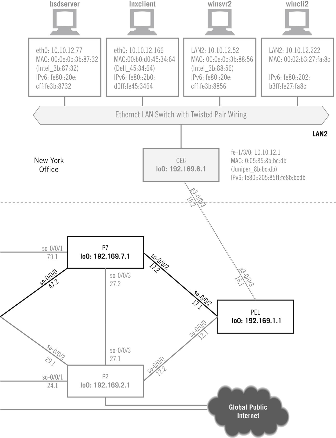
In this chapter, we’ll be using the equipment shown in Figure 31.1. We’ll configure the CE0 at the edge of the network router to do NAT for the clients on LAN1 (bsdclient and wincli1). Before we configure NAT, we’ll have to explore a few of the types of NAT we could use and then configure one of these types for LAN1.

Using NAT
With NAT, a network could support 500 or so hosts with private addresses, and the NAT router could translate these to the public IP address range when the client needed Internet access. After all, the remote server replied blindly to the source IP address, which only needed to be routable and not private. NAT devices could even allow ports to be part of the process (and know that a server’s reply to 10.10.11.177:30567 is different from a reply to 10.10.11.177:31420), even though the IP addresses were the same.
Many DSL access and gateway devices (“DSL routers”) still use this “trick” to allow multiple home computers to share a single IP address from the ISP. Some ISPs are careful to point out that this arrangement is not supported, which always boils down to two things: They won’t tell you how to configure it and you can’t report a problem on it if you do configure it and it doesn’t work. Modern NAT devices know which addresses belong to servers (and should be translated consistently so that clients can find them, or not be translated at all) and which are clients (and can be changed with abandon).
Advantages and Disadvantages of NAT
Today, NAT still offers advantages, but these often have to be balanced against some disadvantages, especially when coupled with current security practices. The advantages to using NAT follow:
Address sharing—A small number of IP addresses can support a larger pool of devices.
Ease of expansion—If the number of hosts grows beyond the public IPv4 space assigned, it’s easy to add hosts.
Local control—Administrators essentially run their own private piece of the public Internet.
Easy ISP changeover—When host addresses are private, public ISP addresses can be changed more easily.
Mainly transparent—Usually, only a handful of devices have to know the NAT rules for a site.
Security—Oversold, but still seen as an advantage. Hackers don’t know the “real” client’s IP address, true, but the true targets are often servers and the NAT “firewalls” themselves.
These NAT pluses have to be balanced against the current list of disadvantages.
Complexity—NAT adds management complexity and makes even routine troubleshooting more difficult.
Public address sensitivity—Private addresses are favored by hackers. Some applications and devices raise flags when presented with private addresses. (One FTP application used for this book insisted on needing to know the “real” public network IP address of the host before it would work properly!)
Application compatibility issues—NAT is not totally transparent. Applications such as FTP, which embed IP addresses and port numbers in data (such as the PASV and PORT messages), must be handled with special care by NAT routers.
Poor host accessibility—NAT makes it difficult to contact local devices from the outside world. NAT is not a good solution for Web sites, FTP servers, or even peer protocols (VoIP) running on a local LAN.
Performance concerns—The burden of hundreds of simultaneous Internet access users today often degrades NAT router performance for its main task: routing packets.
Security—Both a plus and a minus. Modern protocols such as IPSec raise alarms when packet fields are changed between end systems. You can still combine NAT and IPsec (carefully), but keeping NAT as a “security feature” in addition to IPSec can be tricky.
Four Types of NAT
NAT is still a popular thing to do on a network. There are even the following four slightly different versions of NAT that are supported in many routers, and most are known by a number of unofficial names.
• Unidirectional NAT (outbound or “traditional” NAT)
• Bidirectional NAT (inbound or “two-way” NAT)
All of these methods are a little different, but all involve use of the same terms to describe the addresses that are translated. An address can be inside or outside, based on whether it is used on the local LAN (inside) or on the Internet (outside). Addresses can also be local or global, based on whether they are drawn from the private RFC 1918 address ranges (local) or publicly registered or obtained from an ISP (global).
NAT therefore encompasses about four address “types,” which are listed in Table 31.1. In the table, the Martian address ranges 169.254.0.0/16 (used for IPv4 autoconfiguration) and 250.0.0./8 (experimental) are used as “public” addresses to preserve the Illustrated Network’s policy of never using public IP addresses as examples.
Table 31.1
Address Types Used in NAT with Chapter’s Example Values
| Type of Address | Example | Common Use |
| Inside local | 10.100.100.27 | Client’s “native” address used as source in outbound packets and destination inbound |
| Outside local | 172.16.100.13 | Destination address used by client |
| Inside global | 169.254.99.1 | Client’s public address, range assigned by ISP |
| Outside global | 250.99.111.4 | Source and destination address used on Internet |
In addition, the translational mappings that NAT performs can be static or dynamic. Static translations establish a fixed relationship between inside and outside addresses, whereas dynamic mappings allow this relationship to change between one translation and another. These can be mixed, using static mapping for servers (for example) and dynamic for clients, much like DHCP. DNS can be used for NAT purposes as well. Let’s look at how each NAT variation uses these address translation terms and procedures.
Unidirectional NAT
Let’s examine an example for outbound or traditional NAT that will repeat addresses from one NAT type to the other as we show how they differ. Assume that the LAN has 250 hosts that use private (inside local) addresses in the 10.100.100.0/24 range. These hosts use dynamic NAT to share a pool of 20 inside global addresses in the range 169.254.99.1 through 169.254.99.20.
Suppose client host 10.100.100.27 accesses the Web server at public address 250.99.111.4 using unidirectional NAT. What will the router do to the packet addresses and what will the addresses look like at each step along the way—inside to NAT, NAT to outside, outside to NAT, and NAT to inside? Figure 31.2 shows the four steps.
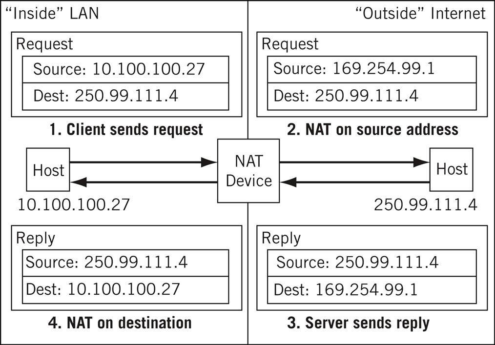
The client’s packet to the server at 250.99.111.4 has its source address changed from 10.100.100.27 (inside private) to 169.254.99.1 (outside global, which must be a routable address). The server replies by swapping source and destination address, and the reply (matching up in the NAT device to the request) is translated back to 10.100.100.27. No one outside the organization knows which host “really” has address 10.100.100.27, although dynamic NAT is better at this concealment than a static NAT mapping.
It might seem that dynamic mapping would always be the proper NAT choice. However, a complication arises when there are two site routers (as is often the case). If the request is sent by one NAT router and the reply received by another NAT router, the translation tables must be the same or chaos will result. Unless the routers constantly communicate NAT information (how?), this makes it difficult to use dynamic mapping.
NAT also handles adjustments other than address translation. The IP checksum must be changed, as well as UPD/TCP checksums. FTP embeds address and port information in data, and these should be changed as well. Finally, ICMP messages include initial header bytes, and even these should be changed when an ICMP message is the reply to a request.
Traditional NAT only handles this type of outbound translation. It cannot handle requests from a device on the public Internet to access a server on the private network (LAN).
Bidirectional NAT
Let’s use the same basic scenario that we employed in the unidirectional NAT example, but upgrade the NAT router to use inbound or two-way NAT. The major difference is that bidirectional NAT allows requests to be initiated from the global public Internet to hosts on the private inside LAN.
This type of NAT is more difficult to implement because, whereas inside users generally know the public addresses of Internet devices, outside devices have no idea what private addresses represent the device on the LAN. And even if they did know them, private RFC 1918 addresses are not routable, so there would be no way to get a packet there anyway. (Home DSL routers, which normally all use NAT by default, have led to an explosion of 10.0.0.0/8 and 192.168.0.0/16 devices around the world—yet another reason some ISPs don’t like to support home servers unless covered by the service offering.)
Static NAT mapping, one for one from local device to public address, is one way to handle the “outside request” issue. Of course, this defeats the more-than-public-address-space support that NAT offers, and makes any security claims hollow. (Packets are blindly forwarded to the target anyway.)
The other solution is to use DNS. As long as the outside request is by name and not IP address, DNS can provide the current private global address of the host (it must be global because it must be routable). In other words, DNS and NAT can work together (as described in RFC 2694), which adds extensions for NAT to DNS (called an application level gateway, or DNS_ALG in the RFC). This solution uses dynamic NAT and is a four-step process. The outside client sends a request to DNS to get the IP address that goes, for instance, with www.natusedhere.com.
The authoritative DNS server for the natusedhere.com domain resolves the name into an inside local (private) address for the host, perhaps 10.100.100.27, as before. The inside local address is now sent to the local NAT device to create a dynamic mapping between this private address and an inside global (public and routable) address. This mapping is used in the NAT translation table. For this example, we’ll use 169.254.99.1, as before.
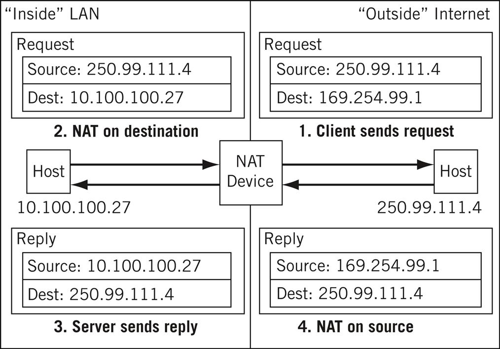
The DNS server replies not with the private (nonroutable) address, but with the mapped address in the NAT reply (in this case, 169.254.99.1), as established in the previous step. Once this DNS/NAT procedure is complete, the transaction in bidirectional NAT continues (as shown in Figure 31.3).
Naturally, requests from local LAN devices are still handled as in unidirectional NAT.
Port-Based NAT
In both unidirectional and bidirectional NAT, the address translation is always one to one. Even when dynamic mapping is used, the entire inside address is always swapped out for an outside address. But we set up our examples by saying that 250 LAN hosts are going to share only 20 public IP addresses.
Unidirectional and bidirectional NAT handles 20 or fewer simultaneous Internet users on the LAN. But what happens when more than 20 hosts are trying to access the Internet all at the same time?
That’s where port-based NAT, also called overloaded NAT, comes in. Some devices even advertise this as network/port address translation (NAPT) or port address translation (PAT), but we’ll just call it port-based NAT.
We are now essentially translating sockets from inside to outside. With port-based NAT, we can easily have all 250 devices with outstanding requests on the Internet all at the same time and never come close to running out of port numbers (which run from 0 to 65,535).
Let’s say that one host on the LAN is already using private address 10.100.100.27 and source port 17000 (perhaps the browser always uses that source port number) to contact a Web site. No problem. Port-based NAT just translates both IP address and port, as shown in Figure 31.4.

Port-based NAT is usually how DSL routers share a single ISP address among four or more home PCs. Most NAT implementations today are capable of port-based operation. However, this does not mean it’s always done when available. Not all applications or their packets use UDP or TCP ports, and port-based NAT cannot be done on these packets.
Overlapping NAT
This last type of NAT, also called “Twice NAT,” is quite different from the three other types. All three previous types used private nonroutable IP addresses as a “substitute” for global routable IP addresses. NAT routers immediately assume that any packets drawn from the local LAN’s private IP address space are a reference to a host within the local LAN. Anything else belongs to the outside world.
But what if the inside addresses overlap entirely or in part with addresses used in the outside world? In other words, what if there is another 10.100.100.0/24 address range on the “outside” that the local device using that private address space must communicate with? There are three major cases where inside addresses on a LAN might be duplicated in the outside world.
Private network to private network—NAT routers tend to use the same private address ranges, such as 10.0.0.0/8 or 192.168.0.0/16. So, this situation arises in DSL router configurations (such as neighbor to neighbor) all the time. And organizations often merge and find two sites now using the same private IP address ranges.
Reassigned addresses—Many customers get their IP address space from their ISP. But what if they change ISPs? The ISP is certainly free to offer that space to someone else. Instead of flash-cutting every IP address on the network, NAT can be used for the new ISP until cut-over is complete. And even if customers pay for their own address spaces, these can be reassigned if the payment is not up to date.
Private IP networks going “public”—This does not occur as often, but it was once common to have huge IP networks within an organization with no Internet access at all. (Networks are for work, the Internet is for play, or so the philosophy went.) So who cared what IP addresses were used on the private network? But if a space such as 9.0.0.0/8 is used (which belonged to IBM) something must be done when Internet connections become essential.
Thus, when a host on the local LAN sends a packet from 10.100.100.27 going to 10.100.100.10, how does it know whether the address is truly local or not? Local frames have local MAC addresses, but “outside” packets are sent in MAC frames that are sent to the router.
Someone has to know where the other address is or there will be no solution. As before, DNS will coordinate with NAT to supply the answer. Overlapping NAT translates both source and destination address.
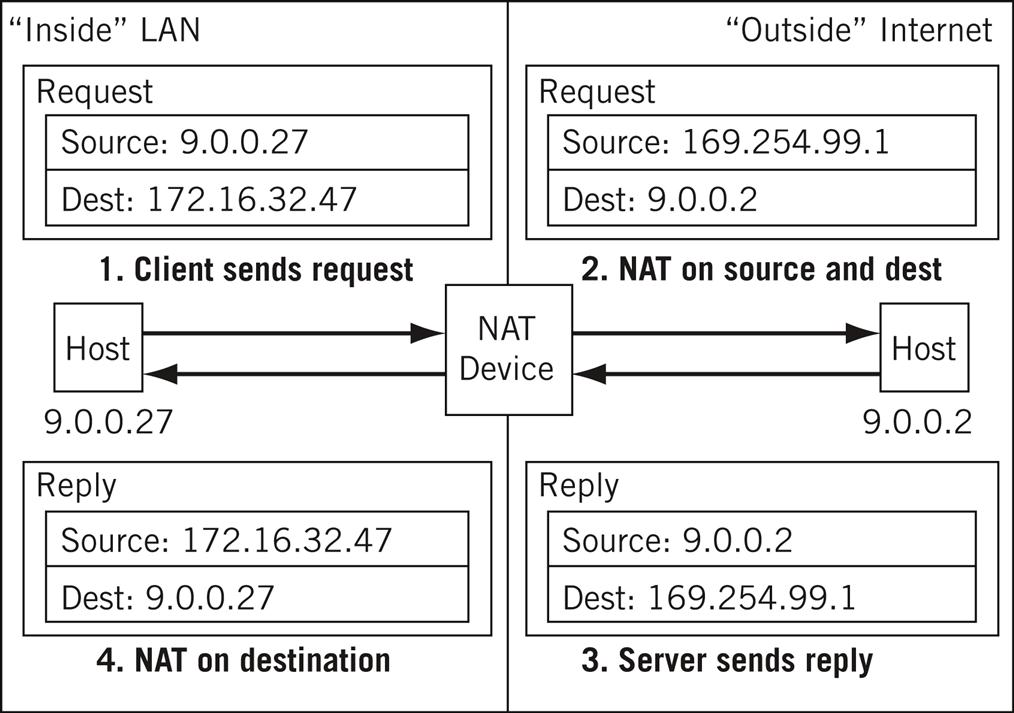
Let’s consider a new example. Our local host is on a LAN that uses the public IP address space 9.0.0.0/8 as a private address. Local host 9.0.0.27 needs to send to a server that turns out to be at IBM and is also 9.0.0.2. The following is what happens.
Local client 9.0.0.27 sends a DNS request to get the address of the Web server at www.twicenatusedhere.com. The NAT router (which must support overlapping NAT, of course) on the local network intercepts the DNS request and uses a table to construct a special mapping for this query. Let’s assume that it will translate www.twicenatusedhere.com into address 172.16.32.47 (another private IP address space). The NAT router knows the real public address of the IBM server, of course.
The NAT router returns this private address to the client, which uses it as the destination address. The NAT router now knows that packets sent to this IP address are for the Web server outside the LAN.
The NAT operation now functions as shown in Figure 31.5. Note the use of the 169.254.99.1 address, which is within the public IP address space of the local LAN.
The NAT is still useful for port-based operations where overloading makes sense (as with home LANs and DSL) and overlapping IP address spaces. However, NAT should never be used as a security method, if only because it gives a false sense of security to users and network administrators.
NAT in Action
What type of NAT should we configure for the Illustrated Network? This could get tricky because we’ve been using private IP addresses as public addresses all along. To make it clear what we’re doing, we’ll limit our NAT activities to LAN1 and use part of the 172.16.0.0/16 private address space as a public address space for our NAT pool (which we’ve not used much so far). Because some applications are more sensitive to substituted addresses than others (such as FTP), we’ll limit our NAT implementation to clients. Because the servers are affected, we’ll use dynamic source NAT. Finally, we’ll configure the popular port-based NAT (NAPT).
First, we have to configure a pool of addresses called NAPT-address-pool to use for NAT on CE0. We’ll map our 10.10.11.0/24 address space to the range from 172.16.11.0 to 172.16.11.255. We’ll set port selection to automatic so that we don’t have to worry about the port range used. We also have to create the “rule” that subjects’ packets arriving on the LAN1 interface to NAT.
The AS PIC is smart enough to match up returning traffic. (We apply the rule in both the input and output direction for LAN1.) In others words, NAT is applied in both directions for NAPT.
set services nat pool NAPT-address-pool address-range low 172.16.11.0
high 172.16.11.255; # establish to address range to use
set services nat pool NAPT-address-pool port automatic;
# port translaton will be done automatically
set services nat rule SOURCE-NAT match-direction input-output;
# NATP will be applied to all packets in either direction
set services nat rule SOURCE-NAT term NO-NAT-FOR-SERVERS from
source-address 10.10.11.66; # lnxserver should not be translated
set services nat rule SOURCE-NAT term NO-NAT-FOR-SERVERS from
source-address 10.10.11.111; # winsrvr1 should not be translated
set services nat rule SOURCE-NAT term NO-NAT-FOR-SERVERS then
no-translation; # this is a keyword for this action
set services nat rule SOURCE-NAT term SOURCE-NAT then translated
translation-type source dynamic; # if not a server, translate
set services nat rule SOURCE-NAT term SOURCE-NAT then translated
source-pool NATP-address-pool; # use automatic port assignments
The absence of a from clause in the term SOURCE-NAT means that the then clause actions are applied to all packets that do not match the term NO-NAT-FOR-SERVERS, which is what we want to do. On the older Juniper Networks router model used on our network, NAT (and several other specialized services) is performed by a special internal interface card called an Adaptive Service Physical Interface Card (AS PIC). (For current NAT configurations on Juniper Networks devices, see www.juniper.net documentation.) This architecture allows the router to forward packets as fast as it can and off-loads any special packet processing to this service’s interface.
Once configured, packets arriving on the LAN1 interface that are subject to NAT are not forwarded right away but sent to the AS PIC interface, which has an internal IP address. Once NAT has been performed, the packets are sent back into the main part of the router for normal table lookups and forwarding.
To get the packet to the AS PIC interface (sp-0/2/0 on CE0), we give the internal interface an IP address (just as any other interface). Then we apply the configured NAT “service set” (which we’ll call SOURCE–NAPT) to the LAN interface we want to apply NAT source address translation to. Another static “next-hop” routing rule gets the translated packets back to the forwarding portion of the router. (We also have to advertise a static route for the NAT address space so that the other routers know where to send packets sent back to the 172.16.11.0/24 address space, but the complete CE0 router configuration for NAT is not shown.) The interface to LAN1 and the AS PIC interface are configured as follows.
set interface fe-1/3/0 unit 0 family inet service input service-set
SOURCE-NAPT;
# configuration of the SOURCE-NAPT service set is not shown
set interface fe-1/3/0 unit 0 family inet service output service-set
SOURCE-NAPT;
set interface fe-1/3/0 unit 0 family inet address 10.10.11.1/24;
# this is a regular LAN1 interface address
set interface sp-0/2/0 unit 0 family inet address 172.16.1.1/24;
# the sp- interface needs and IP address too
We’ll say a little more about the “next-hop” configuration and service sets in Chapter 32 (on stateful firewalls). How do we know that the NAT translation is working? Let’s use our little echo test program from the UDP chapter to send packets from bsdclient on LAN1 at IP address 10.10.11.177 to lnxclient on LAN2 at IP address 10.10.12.166. We’ll capture the packets on lnxclient with tethereal. As expected, the source address has been translated to one in the 172.16.11.0/24 range.
[root@lnxclient admin]# /usr/sbin/tethereal -V
Capturing on eth0
Frame 1 (60 bytes on wire, 60 bytes captured)
Arrival Time: Feb 6, 2008 11:16:03.822845000
Time delta from previous packet: 0.000000000 seconds
Time relative to first packet: 0.000000000 seconds
Frame Number: 1
Packet Length: 60 bytes
Capture Length: 60 bytes
Ethernet II, Src: 00:0e:0c:3b:8 f:94, Dst: 00:b0:d0:45:34:64
Destination: 00:b0:d0:45:34:64 (Intel_45:34:64)
Source: 00:0e:0c:3b:8 f:94 (Intel_3b:8 f:94)
Type: IP (0x0800)
Trailer: 0000000000000000000000000000
Internet Protocol, Src Addr: 172.16.11.177 (172.16.11.177), Dst Addr:
10.10.12.166 (10.10.12.166)
Version: 4
Header length: 20 bytes
...
However, LAN1 traffic from the servers is not translated. This time, we’ll run the echo test program from lnxserver on LAN1 at IP address 10.10.11.66 to lnxclient on LAN2 at IP address 10.10.12.166. We’ll capture the packets on lnxclient with tethereal. As expected, the source address has not been translated to one in the 172.16.11.0/24 range.
[root@lnxclient admin]# /usr/sbin/tethereal -V
Capturing on eth0
Frame 1 (60 bytes on wire, 60 bytes captured)
Arrival Time: Feb 6, 2008 14:37:24.487934000
Time delta from previous packet: 0.000000000 seconds
Time relative to first packet: 0.000000000 seconds
Frame Number: 1
Packet Length: 60 bytes
Capture Length: 60 bytes
Ethernet II, Src: 00:d0:b7:1 f:fe:e6, Dst: 00:b0:d0:45:34:64
Destination: 00:b0:d0:45:34:64 (Intel_45:34:64)
Source: 00:05:85:88:cc:db (Intel_1 f:fe:e6)
Type: IP (0x0800)
Trailer: 0000000000000000000000000000
Internet Protocol, Src Addr: 10.10.11.66 (10.10.11.66), Dst Addr:
10.10.12.166 (10.10.12.166)
Version: 4
Header length: 20 bytes
...
Questions for Readers
The captured listing here shows some of the concepts discussed in this chapter and can be used to answer the following questions.
[root@lnxclient admin]# /usr/sbin/tethereal -V port 7
Capturing on eth0
Frame 1 (60 bytes on wire, 60 bytes captured)
Arrival Time: Feb 6, 2008 16:43:22.458233000
Time delta from previous packet: 0.000000000 seconds
Time relative to first packet: 0.000000000 seconds
Frame Number: 1
Packet Length: 60 bytes
Capture Length: 60 bytes
Ethernet II, Src: 00:d0:b7:1 f:fe:e6, Dst: 00:b0:d0:45:34:64
Destination: 00:b0:d0:45:34:64 (Intel_45:34:64)
Source: 00:05:85:88:cc:db (Intel_1 f:fe:e6)
Type: IP (0x0800)
Trailer: 0000000000000000000000000000
Internet Protocol, Src Addr: 176.16.11.78 (176.16.11.78), Dst Addr:
10.10.12.166 (10.10.12.166)
Version: 4
Header length: 20 bytes
1. Which host has this capture been run on?
2. Which host is responding to the echo?
3. What is the translated address used on the LAN1 host that responded to the echo?
4. What is the host name of the device on LAN1 that responded to the echo?
5. The port numbers are not displayed in the listing. Based on the NAT configuration on CE0, should the port number be translated as well?