 LEDs (27)—I would suggest red, but pink is cool, too
Here is an Arduino-controlled Charliplexed LED heart. It uses a total of 6 wires to control 27 LEDs. Either PIC or AVR could easily be used for this project, but Arduinos are easy to program, very common, and have to have plenty of power left over for input.
For those not familiar, Charlieplexing is a technique for using N inputs to control N x N-1 LEDs. Check out www.instructables.com/id/Charlieplexing-LEDs--The-theory for a great explanation of this technique. Basically it allows you to drive a bunch of LEDs with very few pins.
1. Required materials
LEDs (27)—I would suggest red, but pink is cool, too
Resistors (6) to match your LEDs. I used 100R, but check out http://led.linear1.org/1led.wiz to calculate it based on your LEDs. You can then split that number in half, as there will be one on each wire, but round up as needed. 100R is a good place to start.
A 6-wire cable. I used some 8-wire Category 5 (4 twisted pairs) that I already had.
Soldering iron, solder, wire stripper, wire cutters
Some type of perforated circuit board. I used RadioShack part number 276-148 and it fits the heart perfectly.
Figure E shows the schematic as viewed from the top. You will want to review that before, during, and after building. Once it is built, you will need to test thoroughly. Each two-wire combination to a battery should light up one, and only one, LED. If two LEDs light up, then you have a short. Some ghosting can occur in a second LED when being driven by a strong current source (that is ok, this will not be noticeable when animated). There will be three combinations that won’t light anything up, so don’t worry and just make a note of those. If more than three combinations fail to light up, then you probably have a short, or a fried LED.
2. First layer
Now to begin the soldering. Follow Figures F through I to assemble the first layer. You are going to create 4 sets of two pairs. They will all be aligned in the same way. Then you will connect the middle sections of both the top and bottom. I’ve already started making a connection between the top two, but that will be covered in the next step.
3. Start the layering
Continue to solder and start layering the connections. This is where it starts to get complicated. You are going to mirror the connections you’ve made so far. Whatever you do on the right, do the opposite on the left. Just be careful not to create any shorts, and give the bent wires enough room so they won’t short if moved a little. And be sure to refer back to the schematic often.
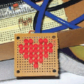
Figure A: The heart, connected to the Arduinocompatible Bare Bones Board

Figure B: The heart in action
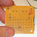
Figure C: I first placed all the LEDs in the board, and then marked it for the LEDs on the outer corners of the heart
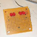
Figure D: Here the LEDs are set right over the marks I made
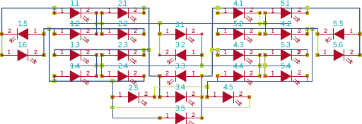
Figure E: The schematic.
Top right positive lead bends over left to the top right negative lead.
Top right set’s bottom negative lead bends to the right to make contact with the positive lead. Do the same for the bottom set.
Bend the top set’s top left negative lead down to the bottom set’s top left negative pin.
Bend the lower right positive lead of the top set down to the lower right positive lead of the bottom set.
Do the opposite on the other side.
It may look bad, but you are going to end up with something that looks like two C’s facing each other on each side. The top middle sections will be joined, as well as the bottom middle sections.
You then add the two center LEDs in opposite alignment of each other. You want the top one to be in the same alignment of all the others so far, and the bottom one to be the opposite. Then you connect the negative of the bottom one to the positive of the top one, and then to the top center connection. You do the opposite for the other two, and connect them to the bottom center connection.
It will be a total of two separate connections on each side, with the two in the middle. The start of the 6 total connections. Now you just need to fill in the other possible combinations (a total of 30).
4. Final layers
The two side pairs need to be installed the same way the middle pair was, but now you connect them to the C-shaped connections closest to them. One to the outer, and the other to the inner of their side.
Then you install the next lower middle pair of two in the same fashion of opposite alignment, and connect them to the two middle C connections. However, don’t connect the bottom-most LED into its set yet, as you are about to bend a lead under that connection (Figure O).
I aligned the next two in the same direction on opposite sides of the bottom middle LED. I bent the positive lead of the right one between the bottom center LED and its mate. Connecting to the negative lead of the bottom left LED, and the outer left C shape. You then take the bottom left LED’s positive lead, and bend it to the bottom right LED’s negative lead, and then to the opposite outer C shape.
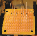
Figure F: Solder the top 4 LEDs into place. Align them all the same way. The row will go: -+ -+ -+ -+
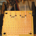
Figure G: Bend the middle pins down and solder them to the board
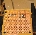
Figure H: You need to solder all 4 of the middle leads together
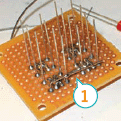
Figure I: Shows a solid connection across the middle sections of the top sets. Do the same across the bottom two sets.
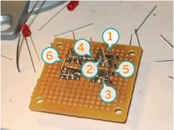
Figure J: 1. Top right positive lead bends over left to the top right negative lead 2. Top right set’s bottom negative lead bends to the right to make contact with the positive lead 3. Same as top right set 4. Bend the top set’s top left negative lead down to the bottom set’s top left negative lead 5. Bend the lower right positive lead of the top set down to the lower right positive lead of the bottom set 6. The mirror opposite of the right set
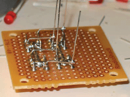
Figure K: Another view of the connections
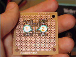
Figure L: 1. The negative leads of both the middle LEDs goes to the bottom center connection 2. The positive leads of the two middle LEDs go to the top center connection
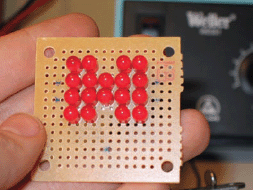
Figure M: You can now address any of these LEDs with different combinations of wires
For the final LED, I bent the positive lead to the bottom middle’s positive lead, and the negative lead to the outer left C shape. Next, clip any stray leads, and make sure there aren’t any shorts.
You will end up with the pairs covering all but three of the possible combinations that six solid connections will give you. So poke around with a 3V positive and negative wire and watch the different LEDs light up one by one.
5. Connecting and programming
All that’s left to do it to wire it up and connect it to an Arduino. Since I’m using Category 5, I’m going to follow its color scheme (see Figure R):
Orange: bottom middle
Orange w: top middle
Blue: inner right C shape
Blue w: outer right C shape
Green: inner left C shape
Green w: outer right C shape
Next, test the connections from the other end of the cable. This makes it easy to touch random combinations to the 3V batteries.
I created a spreadsheet to track the connections (www.makezine.com/go/openheart_spreadsheet). If yours are different for some reason then keep track of the differences, since changes will have to be made when you load the software.
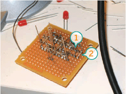
Figure N: 1. Connected to the outer C shape 2. Connected to the inner C shape.
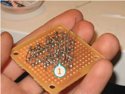
Figure O: The lead (1) goes under the connections made by the lower pair
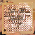
Figure P: The finished connections from behind
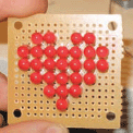
Figure Q: The finished heart
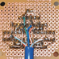
Figure R: Connections for the heart

Figure S: 13 LEDs lit
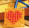
Figure T: All 27 LEDS lit
When I started out, I used a number scheme based on the columns. There were a total of five, with the outer ones having six each (65556). Ignore that for programming, go with the 1-27 one, as it is much easier to address in the program. However, it is still useful while testing, as trying to remember which one is 16 can be crazy, but finding the third one in column 4 (43) is easy. Both are there for you.
The source code that I used for the two animations in the videos is available at www.makezine.com/go/openheart_source. Remember to put a resistor between your Arduino pins and your wires!
Unfortunately there is a limitation on the Arduino’s array size. I’m not sure what it is, which is why I made an array of bytes to save space. Basically you can have any two of the animations, but not all of them. If the Arduino doesn’t respond, comment out some lines of the animation, and then send that over.
Using the latest version of the soft ware from the programmer, you should be able to squeeze at least 500 frames of animation out of the Arduino. Now you’ve got an Arduino-powered animated heart! Check out my blog at http://blog.jimmieprodgers.com for updates on this and other projects.
Jimmie Rodgers is a part-time electronics hobbyist and active Boston Dorkbot member whose dream is to become a full-time Maker. “I love anything dealing with blinking lights and/or sounds, which is why I am starting www.InteractiveLightAndSound.com.”
I’ve developed a kit for the Charlieplexed heart named “Open Heart” that is available in the Maker Shed at www.makershed.com. A Flash programmer is available to generate the animations on my site at www.jimmieprodgers.com/OpenHeartProgrammer.html. The programmer generates the newest version of the code, making it useful even if you make a heart of your own design. You will just need to change out the heartpin array with one that maps to your own.