Give the Gift of Robot Invasion
These adorable little bots are easy to build and make great gifts By Seth Munki

Figure A: Merry Xmas!
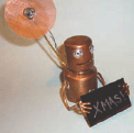
Figure B: ET phone home
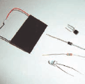
Figure C: The electronics parts you need
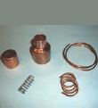
Figure D: The parts to make the body
Give the Gift of Robot Invasion
These adorable little bots are easy to build and make great gifts By Seth Munki
Figure A: Merry Xmas!
Figure B: ET phone home
Figure C: The electronics parts you need
Figure D: The parts to make the body
This solar-powered robot ornament wishes you holiday greetings during the day, but when the lights go out, it radios home for reinforcements!
1. What you need
Electronics:
 A 2N3904 transistor
A rectifier diode
A 1M resistor
A blinking LED
Rechargeable 1.5V batteries (2)
A solar panel
Miscellaneous Parts:
Copper plumbing parts
Grommets
Rivets
Brass and copper wire
LED holder
Copper mesh or beer can
Spring
Epoxy
Hot glue
2. Battery
I used two cells from a rechargeable 9V for some of the bots; for others, I used rechargeable button cells. Be careful when soldering to batteries.
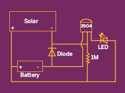
3. Circuit
I found the circuit I used here: http://tinyurl.com/6ayyxf.
I really like the simplicity of this circuit.
4. Robot shell
I decided to use copper plumbing parts because I had them on hand, but this part could really be anything that has enough room to put the electronics in or on.
Drill holes in the end cap for the eyes and in the body for arms, belly button, satellite pole, and wires. I use a hand drill and go slowly, starting with a small bit and stepping up bit size incrementally.
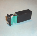
Figure E: Batteries taken from a rechargeable 9V
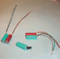
Figure F: The batteries wired up
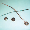
Figure G: You can use button cells, too
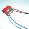
Figure H: Button cells taped together
Figure I: Schematic for the simple “dark activated”
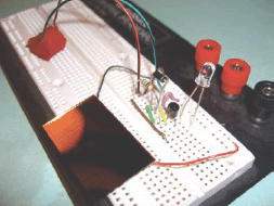
Figure J: Breadboard the circuit circuit
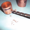
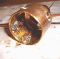
Figure K: Drilling holes for the eyes
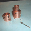
Figure L: Little robot face and body emerges
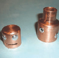
Figure M: Use rivets and grommets for eyes, armholes, and belly buttons
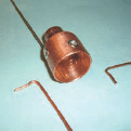
Figure N: Fitting the arms into the body
I made the mouth with a Dremel and a cutoff wheel, but a hacksaw would work well, too.
If you’re feeling fancy and/or have them on hand, finish the holes with aluminum grommets. On some I just used rivets for eyes; on others it’s a grommet and rivet mix.
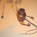
5. Soldering arms
I used a small hobby torch to solder the wire arms onto the body. You will have a much stronger joint if you spend some time fitting the wire so it makes good contact with the inside of the body. I also sand both pieces right before I solder them.
I went with a four-finger-hand approach because it was easier to use small Vs of wire.
I like to pretty much get the arms and fingers into position at this point; if you didn’t do a very good job soldering, they will break off. It’s easier to fix them now, before the electronics are inside.
6. Satellite
This could be anything that kind of resembles a dish. I happened to have some fancy copper mesh/fabric, so I went with that. If this part seems like a pain, you can cut out the bottom of a beer can and use it as is.
If you have the fancy copper, you will still need a beer can. Turn the can over and gently work the copper mesh into the bottom; I used the handle of a screwdriver. Once you have it shaped, cut the excess off with scissors.
Punch the hole in the center after you form the dish; if you do it before, the hole will warp and spread.
I also solder some wires onto the LED at this point. The LED holders I used have a rubber cork that has to be on the LED before soldering.
7. Get ready
Turn the body over and put a piece of tape at the bottom of the neck; this is important because at the end we will be pouring epoxy into the neck.
Figure O: Soldering the arms inside the body
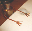
Figure P: Wee little robot hands!
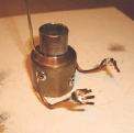
Figure Q: Shape hands so they’re ready to hold the solar panel
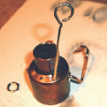
Figure R: Support wire for future satellite tower
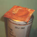
Figure S: Shaping the satellite dish
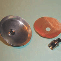
Figure T: Cut the center hole after you shape the dish
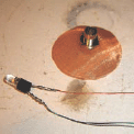
Figure U: Solder wires onto the LED
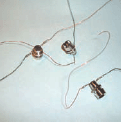
Figure V: LED holders, wired and ready to install
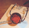
Figure W: Place tape over the neck hole in the body
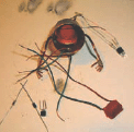
Figure X: Starting to wire things up
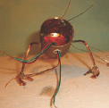
Figure Y: Solar cell leads go through the belly button
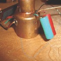
Figure Z: 9V cells are like a backpack
When I used the 9V cells, I kept the batteries on the outside like a backpack; with the button cells, I just stuffed them inside. Either way we need to get those leads ready, either through a hole in the neck if they will be on the outside, or out on the desk if they will be inside.
The LED wires need to be strung through into the interior. The leads for the solar cell need to be put through the belly button; better too long than too short.
8. Solder the circuit
Note: Diode terminology is confusing; I’m going to call the end of the diode with the white stripe the negative (-) terminal. Looking at these pictures, it may be hard to figure out what attaches to what, but it should be clearer when you’re holding the components in your hands. Solder the components together (Figures ZB–ZE).
STEP 1: |
STEP 2: |
+ Solar |
PIN 1 |
+ Battery |
- Battery |
Resistor |
+ Diode |
+ LED |
|
STEP 3: |
STEP 4: |
PIN 2 |
PIN 3 |
- Solar |
- LED |
- Diode |
Resistor |
Figure ZA: Button cells tucked inside
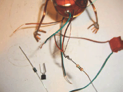
Figure ZB: Soldering STEP 1
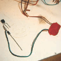
Figure ZC: Soldering STEP 2

Figure ZD: Soldering STEP 3
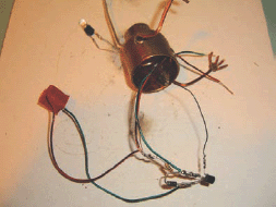
Figure ZE: Soldering STEP 4
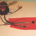
Figure ZF: Position parts on tape so they don’t touch
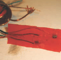
Figure ZG: Secure with more tape
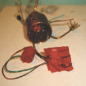
Figure ZH: Fold it so it will fit inside the body
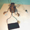
Figure ZI: Solder on the solar panel
After you have it soldered together, cover the solar panel and make sure the LED starts to blink. Tape everything up so the leads don’t touch, and fold it into a shape that is going to fit inside.
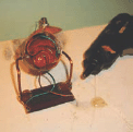
9. Attach solar panel
Solder the solar panel to the leads. Carefully position the panel into the hands. Flip over and hot glue the panel in place. I also use hot glue to hold the electronics inside.
Attach satellite dish to pole and position at a rakish angle.
10. Put your head on
Use epoxy to glue the spring inside the head. After it cures mix another batch of epoxy and pour into the neck; hold the head in place until the epoxy cures. This creates a nice “bobblehead” effect.
Figure ZJ: Hold with hot glue
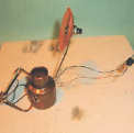
Figure ZK: Add the satellite dish and position it

Figure ZL: Put the LED in the holder on the dish
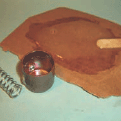
Figure ZM: Mix up your epoxy
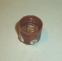
Figure ZN: Epoxy the spring inside the head
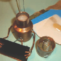
Figure ZO: Adding more epoxy into the neck
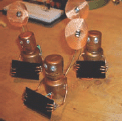
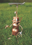
Figure ZP: Your legion of robots is almost ready to do your bidding!
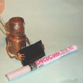
Figure ZQ: Write the message of your choice on the solar panel
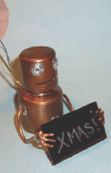
Figure ZR: Leave most of the solar panel exposed
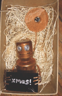
Figure ZS: Packaged for Christmas
11. Write your message
If you’re anal, or just like to make life easier for yourself, you should probably do this step before you attach the solar panel.
I used a semi-fine point silver paint pen. Leave most of the solar panel exposed so the batteries can charge.
12. Start the invasion
Box these up and give them away. I packaged mine a couple of days before Christmas and they were still blinking when they were unwrapped.
User Notes
masynmachien made some using cannibalized solar garden lights
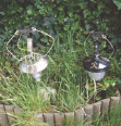
Mutant solar-powered garden light robots
You can play with the resistor value to determine how sensitive the solar panel is. With the 1M resistor it has to be pretty dark before the LED starts blinking. With a 100k resistor it will blink in a lit room, but turn off in direct sunlight. It all depends on how sneaky you want your robot to be.
Seth Munki lives in Oakland, California, with his insanely talented wife Maggie, and is a founding member of “The Dragon Club.”