Chapter 3
Virtual Networking
IN THIS CHAPTER
 Categorizing virtual switches
 Understanding how to create a virtual switch
 Digging deeper with Hyper-V networking
One of the most foundational topics when you’re learning about virtual machines (VMs) and Hyper-V is virtual networking. Virtual networking can be a difficult shift for those who are used to physical network equipment. Virtual networking not only requires changing the way that things are done, but also opens the door for so many more possibilities.
For example, in the past, when you got a new physical server, you needed someone to configure a switch port for your server, and then someone had to run the cables. With Hyper-V virtual switches, that need is taken out of the equation — you can simply assign a VM to a virtual switch, and Hyper-V handles a lot of the configuration for you. You can get into the weeds if you want to, of course, but you don’t have to.
The virtual switch in Hyper-V allows VMs to communicate with each other, with the host system they’re on, and with systems that are on other networks.
In this chapter, I introduce you to virtual networking in Hyper-V, fill you in on the types of virtual switches, and explain how to create switches and do some more advanced network configurations.
Identifying the Types of Virtual Switches
Hyper-V gives you three different types of virtual switches to work with: external, internal, and private. The type of virtual switch you create will depend entirely on what kinds of communication you want to allow to occur. In the following sections, I introduce you to each type of switch and show you where they would be the best fit.
External
When you first configure Hyper-V, you’re asked to assign a network adapter for a virtual switch. This is an external switch. External switches allow you to reach out to other networks, including the Internet. An external switch is close to the traditional network switch, given the way that it’s used.
The biggest differentiator between external virtual switches and internal or private virtual switches is that external virtual switches are the only ones that are assigned to a physical network adapter. This is what allows them to access your physical network.
Internal
The internal virtual switch allows VMs to talk to one another (as long as they’re on the same host) and to their Hyper-V host. VMs may not communicate with VMs on other Hyper-V hosts or anywhere else on the network. Internal virtual switches are not assigned a network adapter on the physical host; they’re assigned a vNIC, which facilitates communication between the VMs and the Hyper-V host.
Internal virtual switches are most useful for traffic related to monitoring by the Hyper-V host, including heartbeat traffic, which is used to confirm that a system is up by sending packets back and forth. If the host doesn’t receive a packet back from the VM guest, it can restart the VM.
Private
The private virtual switch allows you create a truly isolated network segment. It allows VMs on the same Hyper-V to communicate with one another. It does not allow the VMs to communicate with the Hyper-V host. Private virtual switches are not assigned a network adapter.
Private virtual switches are very useful when you need to isolate a network environment, as you do in a development, test, or lab network.
Creating a Virtual Switch
Now that you have an understanding of the types of switches available to you in Hyper-V, you’re probably ready to actually create a virtual switch and start having some fun. You can create a virtual switch through Hyper-V Manager or through PowerShell. I walk you through both options in this section.
Hyper-V Manager
Creating a virtual switch in Hyper-V Manager is how many system administrators start out. Hyper-V Manager is an easy-to-use interface, and creating the virtual switch takes just a few minutes. For this example, I’ll create an external virtual switch. The creation of an internal or private virtual switch is identical, except you don’t select a network adapter with either the internal or private virtual switch.
Follow these steps:
- From Server Manager, choose Tools⇒ Hyper-V Manager.
- Right-click the name of your Hyper-V server and choose Virtual Switch Manager.
-
With External selected, click the Create Virtual Switch button.
The Virtual Switch Properties screen appears. Here, you can customize the settings of the virtual switch.
- Give your virtual switch a name.
- Ensure the radio button for External Network is selected, and from the drop-down list, select the network adapter the switch will use, as shown in Figure 3-1.
- Click Apply, and then click OK.
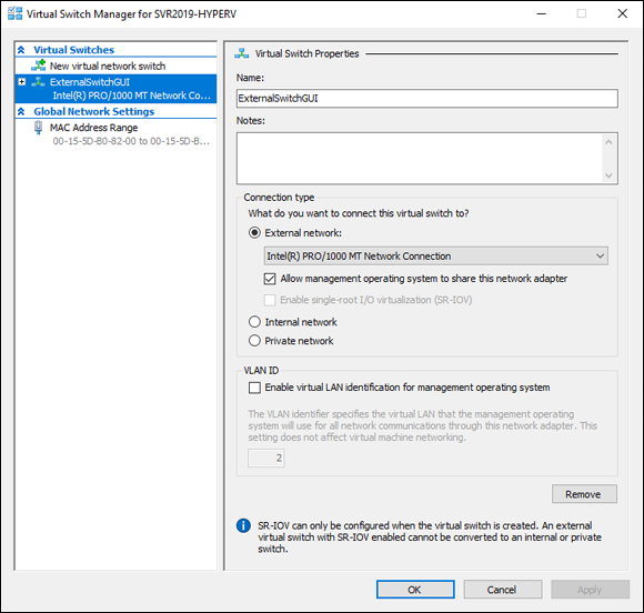
FIGURE 3-1: Under Connection Type, you need to select External Network and select a network adapter to create an external virtual switch.
PowerShell
Creating a virtual switch in PowerShell can be just as simple as it is through the graphical user interface (GUI) when you understand which parameters PowerShell needs to create the type of switch you want.
External
To create an external virtual switch in PowerShell, you need to find out what the name of the network adapter is that you want to use. To do this, you can run the following command:
Get-NetAdapter
In my case, my network adapter is named Ethernet0. So, to create the external virtual switch, the command looks like this:
New-VMSwitch -name PSExternalSwitch -NetAdapterName Ethernet0 -AllowManagementOS $true
This command tells PowerShell that I want to create a new virtual switch, that I want to name it PSExternalSwitch, that I want it to be an external switch (because I’m specifying a network adapter), and that I’ll allow the management operating system (OS) to use it. (In Hyper-V Manager, there was a check box that was checked by default to allow this same thing.)
Start to finish, Figure 3-2 shows you what creating an external virtual switch looks like.
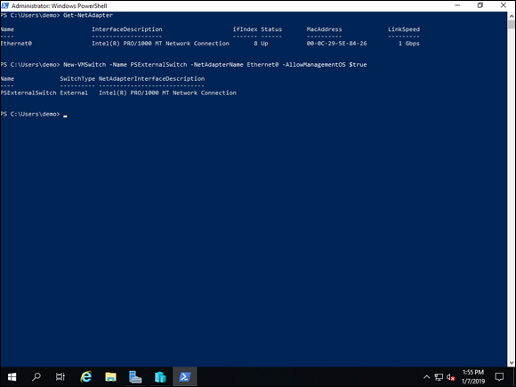
FIGURE 3-2: Creating an external virtual switch requires finding the name of the network adapter you want to use.
Internal
Creating an internal virtual switch does not require any knowledge of the network adapters on the system because it doesn’t use them. Instead, you specify what you want your switch to be named and what type of switch you want it to be.
The code to create an internal virtual switch looks like this:
New-VMSwitch -name PSInternalSwitch -SwitchType Internal
Private
Private virtual switches are very similar in creation to internal virtual switches. The only difference is that the -SwitchType parameter is used to set the virtual switch as a private virtual switch:
New-VMSwitch -name PSPrivateSwitch -SwitchType Private
You can always go back into Hyper-V Manager if you want to view your switches in a graphical format. Figure 3-3 shows the Virtual Switch Manager with the three virtual switches that were created in this section.
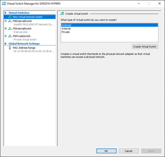
FIGURE 3-3: All your virtual switches will show up in the Virtual Switch Manager regardless of where they’re created.
Getting into Advanced Hyper-V Networking
Networking in Hyper-V offers a wide array of features that make it usable and scalable in an enterprise situation. In this section, I cover a few of the more common features that come in handy in enterprise environments.
Virtual local area network tagging
Virtual local area networks (VLANs) are used to isolate network traffic. You may want to do this for security reasons, or you may do it to improve network performance by decreasing the size of the broadcast domain.
VLAN tagging is used to identify packets as they travel through trunks (which are used for communications between switches). You don’t have to give up the ability to do VLAN tagging when you make the move to a virtualized environment. You do need to ensure that both the network adapters and the physical network that switch the host is connected to support VLAN tagging. Assuming they do, you turn on VLAN tagging on the virtual external switch, and then on the individual VMs. In the following sections, I cover the steps involved in enabling VLAN tagging.
Enabling VLAN tagging on the switch
The first step to using VLAN tagging is to enable it on the virtual switch. This will add the VLAN tag to traffic that is going through the virtual switch for the Hyper-V host (management OS). Follow these steps:
- From Hyper-V Manager, right-click the name of the Hyper-V server and choose Virtual Switch Manager.
- Select the external virtual switch you want to configure, and select the Enable Virtual LAN Identification for Management Operating System check box.
- Set the VLAN ID number to whatever you need to use (see Figure 3-4).
- Click Apply, and then click OK.
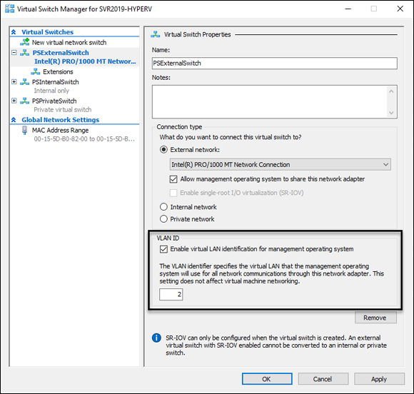
FIGURE 3-4: To enable VLAN tagging on the virtual switch, you need to select the check box and set which ID number you want the switch to use.
Enabling VLAN tagging on the virtual machine
Now that VLAN tagging is enabled on the switch, you’re ready to enable it for a VM. Follow these steps:
- From Hyper-V Manager, right-click the VM and choose Settings.
- Select the network adapter that is connected to the external switch where you just enabled VLAN tagging.
-
Select the Enable Virtual LAN Identification check box and set the VLAN ID number, as shown in Figure 3-5.
The VLAN ID number should match what is set on the switch.
- Click Apply, and then click OK.
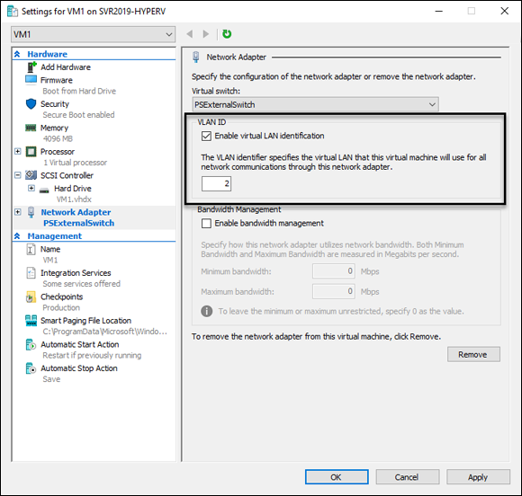
FIGURE 3-5: To enable VLAN tagging on the VM, select the check box and set the VLAN ID.
Bandwidth management
For each network adapter that is connected to a VM, you can set up bandwidth management. Bandwidth management allows you to specify a minimum or maximum amount of bandwidth in Megabits per second (Mbps) that the network adapter is allowed to use. Setting either bandwidth setting to 0 means that it’s unrestricted. In my example in Figure 3-6, you can see that I’ve set the minimum to unrestricted but the maximum to 1024 Mbps.
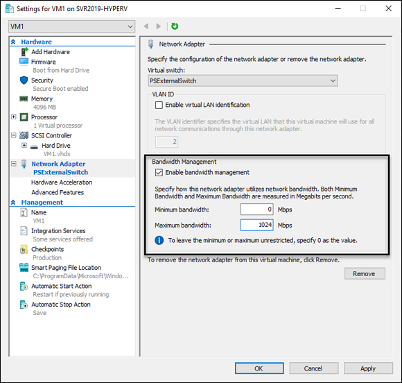
FIGURE 3-6: Setting a maximum amount of bandwidth for a VM can prevent the VM from saturating a network adapter.
To make changes to the bandwidth, follow these steps:
- From Hyper-V Manager, right-click the VM and choose Settings.
- Select Network Adapter.
- Select the Enable Bandwidth Management check box and make the changes to Minimum and Maximum that you want.
- Click Apply, and then click OK.
Network interface card teaming
Network interface card (NIC) teaming can help to reduce bandwidth constraints by allowing you to pair two network adapters so that they act like one network adapter. There are some prerequisites that you need to meet before you can configure your VM to use NIC teaming:
- The Hyper-V host must have at least two network adapters to support NIC teaming.
- If the network adapters on the Hyper-V host are on separate physical switches, they must be in the same subnet.
- You need to create a separate external virtual switch and attach it to each network adapter in the NIC teaming pair.
- The VM that you want to use NIC teaming with has to be connected to both virtual switches.
In the following sections, I walk you through the steps needed to configure NIC teaming in Hyper-V.
Creating the two virtual switches
First, you need to create the two virtual switches and assign them to network adapters. Follow these steps:
- From Hyper-V Manager, right-click the Hyper-V host and select Virtual Switch Manager.
- Select New Virtual Network Switch and click Create Virtual Switch.
- Name the switch, ensure that it’s set to External Network, and choose one of the unused network adapters, as shown in Figure 3-7.
- Click Apply.
- Repeat steps 2 through 4 for the second virtual switch.
- Click OK.
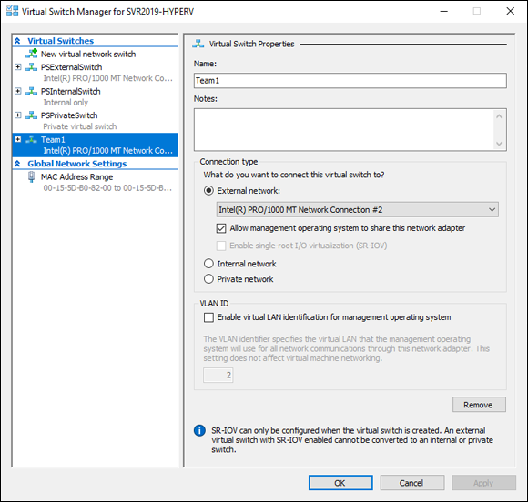
FIGURE 3-7: To support NIC teaming, you must create two virtual switches connected to two separate network adapters.
Creating the network adapters on the virtual machine and enabling network interface card teaming
Now that the virtual switches are created, they have to be attached to the VM that you want to create the team on. To do this, you add two network adapters to the VM. Each of these network adapters will be assigned to one of the switches you created previously. Follow these steps:
- Right-click the virtual machine and select Settings.
- Click Add Hardware and choose Network Adapter.
- Click Add.
-
On the configuration page for the network adapter, choose one of the virtual switches you just created.
In my case, that virtual switch is named Team1.
- Press the plus sign (+)next to the Team1 Network Adapter and select Advanced Features.
- Scroll down to where it says NIC Teaming and select the check box next to Enable This Network Adapter to Be Part of a Team in the Guest Operating System.
- Click Apply,
- Repeat steps 2 through 7 to create the second network adapter and assign it to the second virtual switch you created.
- Click OK.
Creating the network interface card team
The final step involves logging into the VM and completing the configuration of the NIC team there. Follow these steps:
- From Server Manager, click Local Server.
-
Find NIC Teaming, and click where it says Disabled.
You get the NIC Teaming screen similar to Figure 3-8.
-
Select Ethernet 2 and Ethernet 3 (yours may be named differently).
You can hold down the Ctrl key to select them both.
- With the two network adapters highlighted, click Tasks and then click Add to New Team.
- Name your team.
-
Click Additional Properties and make your selections.
I’ve set Teaming Mode to Switch Independent, Load Balancing Mode to Address Hash, and Standby Adapter to None, as shown in Figure 3-9.
Here’s what these settings mean:
- Teaming Mode: With Teaming Mode, you have two options. You can choose Switch Independent or Switch Dependent. With Switch Independent, the switches are not aware of the NIC team’s existence and make no determination on how traffic should be distributed. Switch Dependent implies that the switch will determine how to distribute traffic.
-
Load Balancing Mode: There are three load balancing modes — Address Hash, Hyper-V Port, and Dynamic.
Address Hash creates a hash that is based on the addressing of the packet. The hash is then assigned to one of the adapters.
In Hyper-V Port, VMs get independent MAC addresses. This can’t be used on a NIC team inside of a VM. It’s recommended to use address hashing instead of Hyper-V port for that use case.
If you select Dynamic, outbound traffic is based on a hash made from the TCP port and IP address. Inbound loads are treated the same as Hyper-V Port style. Dynamic has the best performance of the three modes.
- Click OK.
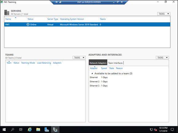
FIGURE 3-8: The NIC Teaming screen is where you can set up the network adapters for teaming inside of the operating system.
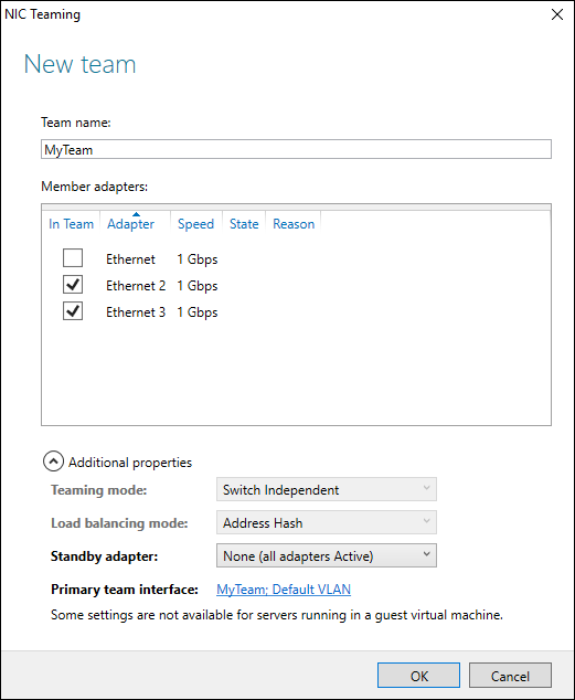
FIGURE 3-9: Configuring the team can be simple, or it can be a bit more advanced by expanding the Additional Properties.
It will take a moment for the teamed NICs to come up, but when they do, they’ll both show Active and you’ll begin to get traffic statistics for them (as shown in Figure 3-10).
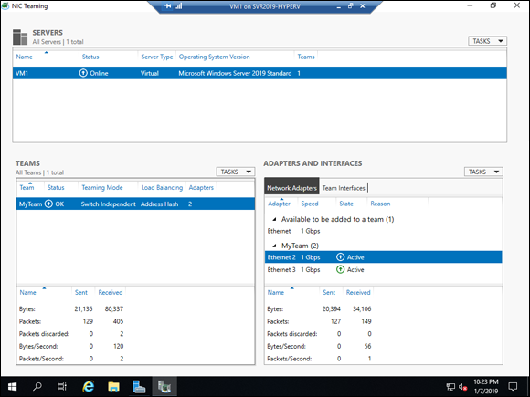
FIGURE 3-10: The configured NIC Team gives you the health status and statistics on how much traffic is passing through.
Looking at single-root I/O virtualization
Single-root I/O virtualization (SR-IOV) can reduce latency for virtual machines by bypassing the software layers of Hyper-V networking and allowing more direct access to the host’s network card. To use SR-IOV, you must have a network adapter that supports it, and the system’s motherboard and firmware must support it as well.
To begin using SR-IOV, it needs to be enabled for the virtual switch, and then for the virtual network adapter of the VM that you want configure to use SR-IOV. You can’t enable SR-IOV after a switch has been created — you need to create a new virtual switch. Follow these steps:
- From Server Manager, choose Tools ⇒ Hyper-V Manager.
- On the right side of the screen, click Virtual Switch Manager.
- Click New Virtual Network Switch, and click External.
- Click the Create Virtual Switch button.
- Name your switch and then select the Enable Single-Root I/O Virtualization (SR-IOV) check box, as shown in Figure 3-11.
- Click OK.
- When you’re warned about your pending change affecting network connectivity, click Yes.
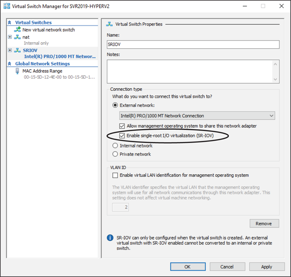
FIGURE 3-11: You must enable SR-IOV on the virtual switch before you can enable it on a virtual machine.
Now SR-IOV is enabled on the new switch, so you can assign the switch to a VM and check the SR-IOV option for the VM as well. Follow these steps:
- From Hyper-V Manager, right-click the virtual machine you want to configure, and click Settings.
- Click Network Adapter, and use the drop-down list box to choose the virtual switch where you enabled SR-IOV.
- Click Apply so that the change is saved.
- Click the plus sign next to Network Adapter, and click Hardware Acceleration.
- Select the Enable SR-IOV check box (shown in Figure 3-12), and then click OK.
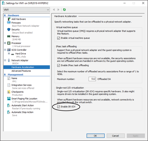
FIGURE 3-12: The option to enable SR-IOV is in the Hardware Acceleration section of the Network Adapter.
 Hyper-V hosts can have multiple virtual switches. A virtual machine can have one virtual switch per network adapter. So if you have a virtual machine that needs access to two virtual switches, you need two separate virtual network adapters.