Parallel programming is not really about driving in the fast lane. It is actually about driving fast in all the lanes. This chapter is all about enabling us to put our code everywhere that we can. We choose to enable all the compute resources in a heterogeneous system whenever it makes sense. Therefore, we need to know where those compute resources are hiding (find them) and put them to work (execute our code on them).
We can control where our code executes—in other words, we can control which devices are used for which kernels. SYCL provides a framework for heterogeneous programming in which code can execute on a mixture of a host CPU and devices. The mechanisms which determine where code executes are important for us to understand and use.
This chapter describes where code can execute, when it will execute, and the mechanisms used to control the locations of execution. Chapter 3 will describe how to manage data so it arrives where we are executing our code, and then Chapter 4 returns to the code itself and discusses the writing of kernels.
Single-Source
SYCL programs can be single-source, meaning that the same translation unit (typically a source file and its headers) contains both the code that defines the compute kernels to be executed on SYCL devices and also the host code that orchestrates execution of those kernels. Figure 2-1 shows these two code paths graphically, and Figure 2-2 provides an example application with the host and device code regions marked.
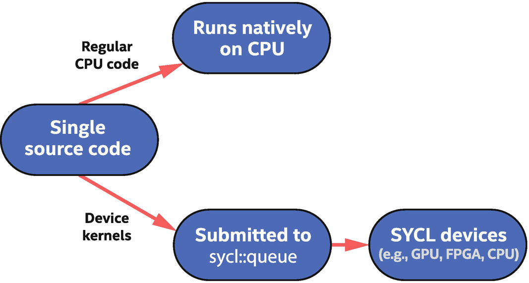
Single-source code contains both host code (runs on CPU) and device code (runs on SYCL devices)
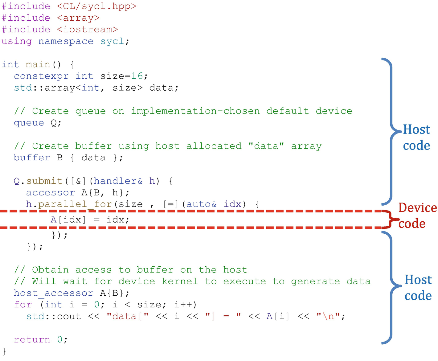
Simple SYCL program
Host Code
Applications contain C++ host code, which is executed by the CPU(s) on which the operating system has launched the application. Host code is the backbone of an application that defines and controls assignment of work to available devices. It is also the interface through which we define the data and dependences that should be managed by the runtime.
Host code is standard C++ augmented with SYCL-specific constructs and classes that are designed to be implementable as a C++ library. This makes it easier to reason about what is allowed in host code (anything that is allowed in C++) and can simplify integration with build systems.
SYCL applications are standard C++ augmented with constructs that can be implemented as a C++ library.
A SYCL compiler may provide higher performance for a program by “understanding” these constructs.
The host code in an application orchestrates data movement and compute offload to devices, but can also perform compute-intensive work itself and can use libraries like any C++ application.
Device Code
Devices correspond to accelerators or processors that are conceptually independent from the CPU that is executing host code. An implementation must expose the host processor also as a device, as described later in this chapter, but the host processor and devices should be thought of as logically independent from each other. The host processor runs native C++ code, while devices run device code.
- 1.
It executes asynchronously from the host code. The host program submits device code to a device, and the runtime tracks and starts that work only when all dependences for execution are satisfied (more on this in Chapter 3). The host program execution carries on before the submitted work is started on a device, providing the property that execution on devices is asynchronous to host program execution, unless we explicitly tie the two together.
- 2.
There are restrictions on device code to make it possible to compile and achieve performance on accelerator devices. For example, dynamic memory allocation and runtime type information (RTTI) are not supported within device code, because they would lead to performance degradation on many accelerators. The small set of device code restrictions is covered in detail in Chapter 10.
- 3.
Some functions and queries defined by SYCL are available only within device code, because they only make sense there, for example, work-item identifier queries that allow an executing instance of device code to query its position in a larger data-parallel range (described in Chapter 4).
In general, we will refer to work including device code that is submitted to the queue as actions. In Chapter 3, we will learn that actions include more than device code to execute; actions also include memory movement commands. In this chapter, since we are concerned with the device code aspect of actions, we will be specific in mentioning device code much of the time.
Choosing Devices
Method#1: Running device code somewhere, when we don’t care which device is used. This is often the first step in development because it is the simplest.
Method#2: Explicitly running device code on the host device, which is often used for debugging. The host device is guaranteed to be always available on any system.
Method#3: Dispatching device code to a GPU or another accelerator.
Method#4: Dispatching device code to a heterogeneous set of devices, such as a GPU and an FPGA.
Method#5: Selecting specific devices from a more general class of devices, such as a specific type of FPGA from a collection of available FPGA types.
Developers will typically debug their code as much as possible with Method#2 and only move to Methods #3–#5 when code has been tested as much as is practical with Method#2.
Method#1: Run on a Device of Any Type
When we don’t care where our device code will run, it is easy to let the runtime pick for us. This automatic selection is designed to make it easy to start writing and running code, when we don’t yet care about what device is chosen. This device selection does not take into account the code to be run, so should be considered an arbitrary choice which likely won’t be optimal.
Before talking about choice of a device, even one that the implementation has selected for us, we should first cover the mechanism through which a program interacts with a device: the queue.
Queues
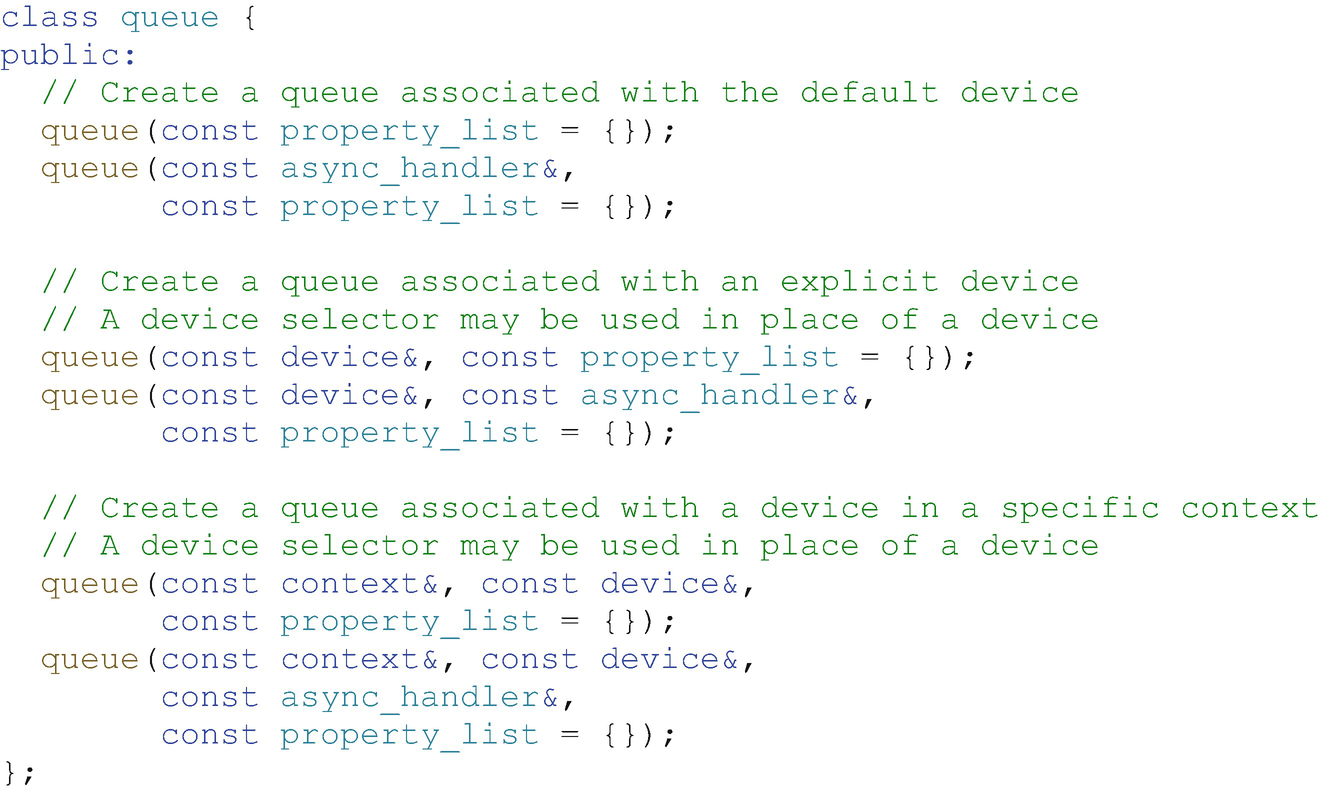
Simplified definition of the constructors of the queue class
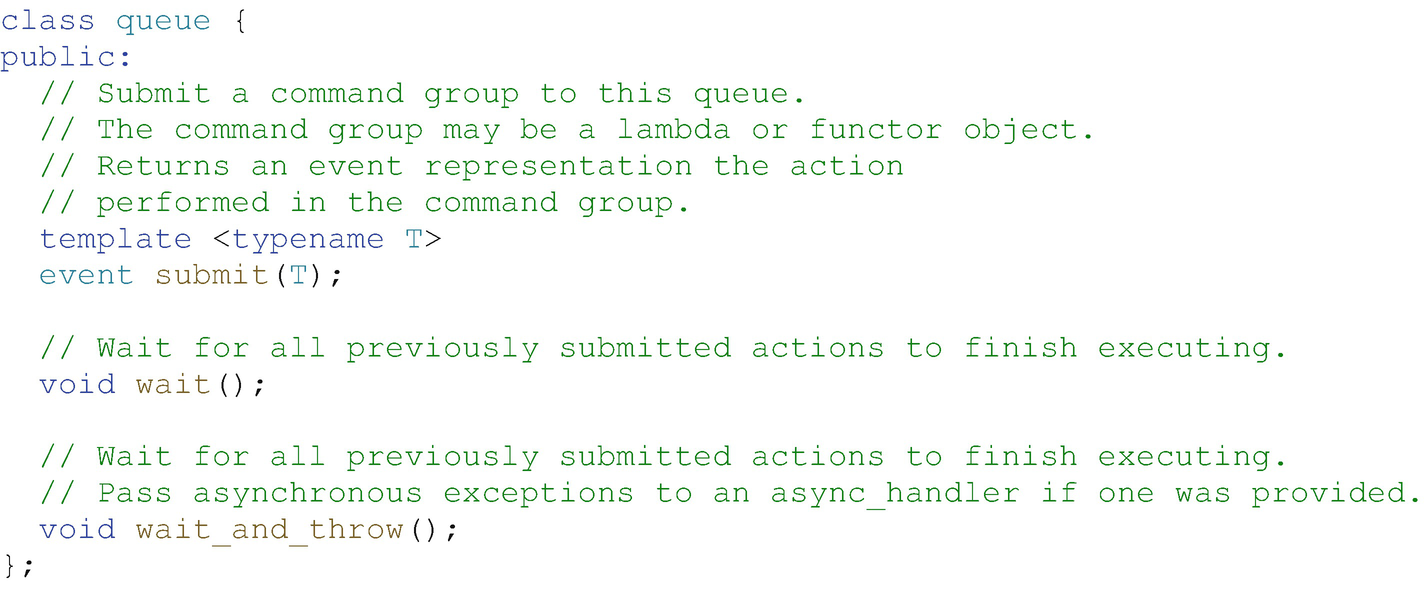
Simplified definition of key member functions in the queue class
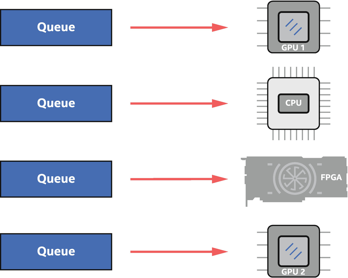
A queue is bound to a single device. Work submitted to the queue executes on that device
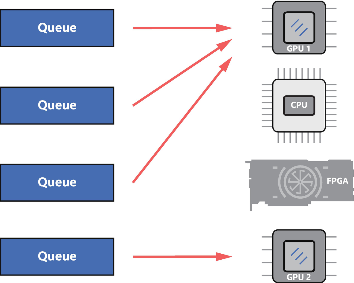
Multiple queues can be bound to a single device
Because a queue is bound to a specific device, queue construction is the most common way in code to choose the device on which actions submitted to the queue will execute. Selection of the device when constructing a queue is achieved through a device selector abstraction and associated device_selector class .
Binding a Queue to a Device, When Any Device Will Do
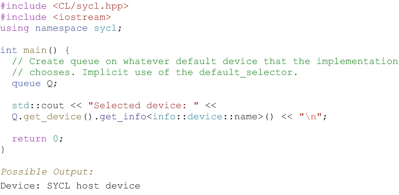
Implicit default device selector through trivial construction of a queue
Using the trivial queue constructor is a simple way to begin application development and to get device code up and running. More control over selection of the device bound to a queue can be added as it becomes relevant for our application.
Method#2: Using the Host Device for Development and Debugging
- 1.
Development of device code on less capable systems that don’t have any accelerators: One common use is development and testing of device code on a local system, before deploying to an HPC cluster for performance testing and optimization.
- 2.
Debugging of device code with non-accelerator tooling: Accelerators are often exposed through lower-level APIs that may not have debug tooling as advanced as is available for host CPUs. With this in mind, the host device is expected to support debugging using standard tools familiar to CPU developers.
- 3.
Backup if no other devices are available, to guarantee that device code can be executed functionally: The host device implementation may not have performance as a primary goal, so should be considered as a functional backup to ensure that device code can always execute in any application, but not necessarily a path to performance.
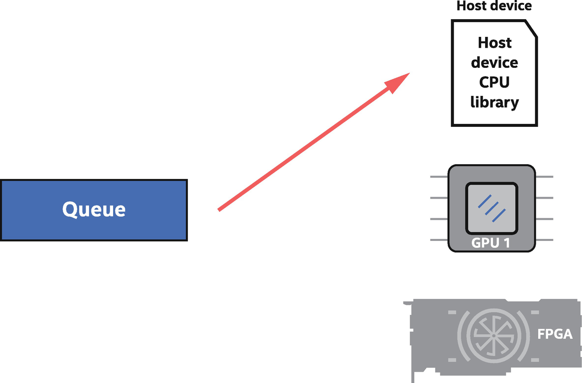
The host device, which is always available, can execute device code like any accelerator
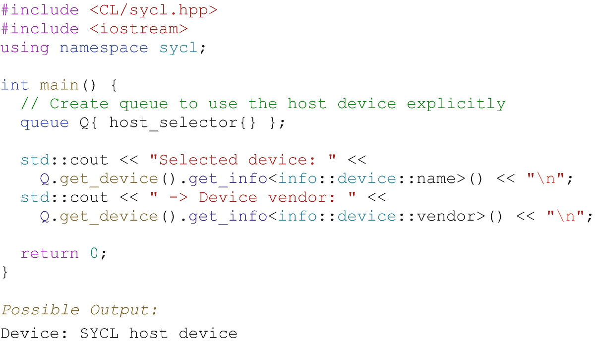
Selecting the host device using the host_selector class
Even when not specifically requested (e.g., using host_selector), the host device might happen to be chosen by the default selector as occurred in the output in Figure 2-7.
A few variants of device selector classes are defined to make it easy for us to target a type of device. The host_selector is one example of these selector classes, and we’ll get into others in the coming sections.
Method#3: Using a GPU (or Other Accelerators)
GPUs are showcased in the next example, but any type of accelerator applies equally. To make it easy to target common classes of accelerators, devices are grouped into several broad categories, and SYCL provides built-in selector classes for them. To choose from a broad category of device type such as “any GPU available in the system,” the corresponding code is very brief, as described in this section.
Device Types
- 1.
The host device, which has already been described.
- 2.
Accelerator devices such as a GPU, an FPGA , or a CPU device, which are used to accelerate workloads in our applications.
Accelerator Devices
- 1.
CPU devices
- 2.
GPU devices
- 3.
Accelerators, which capture devices that don’t identify as either a CPU device or a GPU device. This includes FPGA and DSP devices.
A device from any of these categories is easy to bind to a queue using built-in selector classes, which can be passed to queue (and some other class) constructors.
Device Selectors
default_selector | Any device of the implementation’s choosing. |
host_selector | Select the host device (always available). |
cpu_selector | Select a device that identifies itself as a CPU in device queries. |
gpu_selector | Select a device that identifies itself as a GPU in device queries. |
accelerator_selector | Select a device that identifies itself as an “accelerator,” which includes FPGAs. |
INTEL::fpga_selector | Select a device that identifies itself as an FPGA. |
A queue can be constructed using one of the built-in selectors, such as

Figure 2-10 shows a complete example using the cpu_selector, and Figure 2-11 shows the corresponding binding of a queue with an available CPU device.
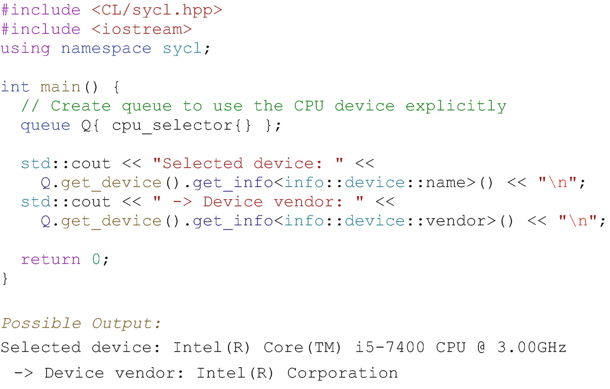
CPU device selector example
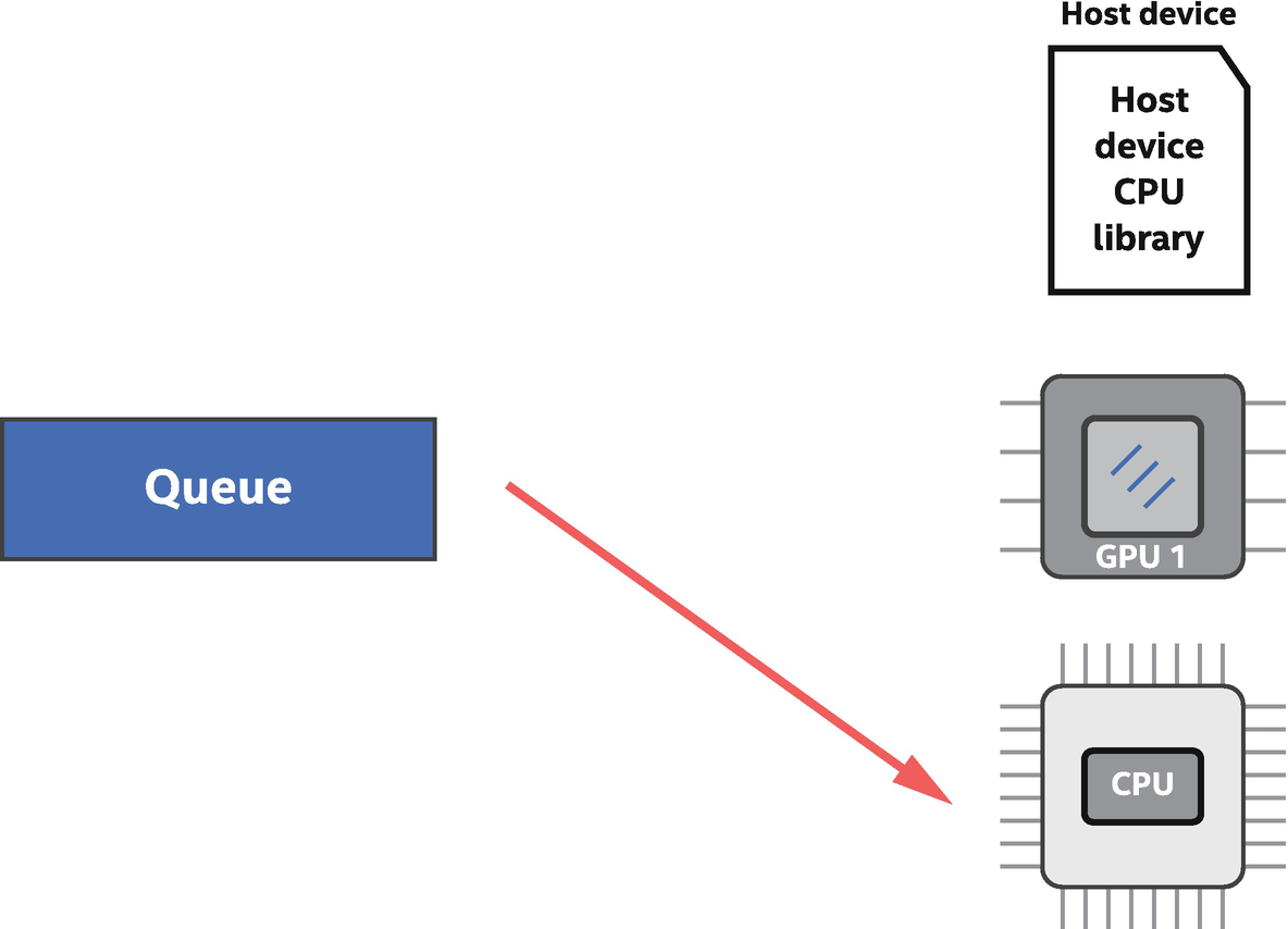
Queue bound to a CPU device available to the application

Example device identification output from various classes of device selectors and demonstration that device selectors can be used for construction of more than just a queue (in this case, construction of a device class instance)
When Device Selection Fails
If a gpu_selector is used when creating an object such as a queue and if there are no GPU devices available to the runtime, then the selector throws a runtime_error exception. This is true for all device selector classes in that if no device of the required class is available, then a runtime_error exception is thrown. It is reasonable for complex applications to catch that error and instead acquire a less desirable (for the application/algorithm) device class as an alternative. Exceptions and error handling are discussed in more detail in Chapter 5.
Method#4: Using Multiple Devices
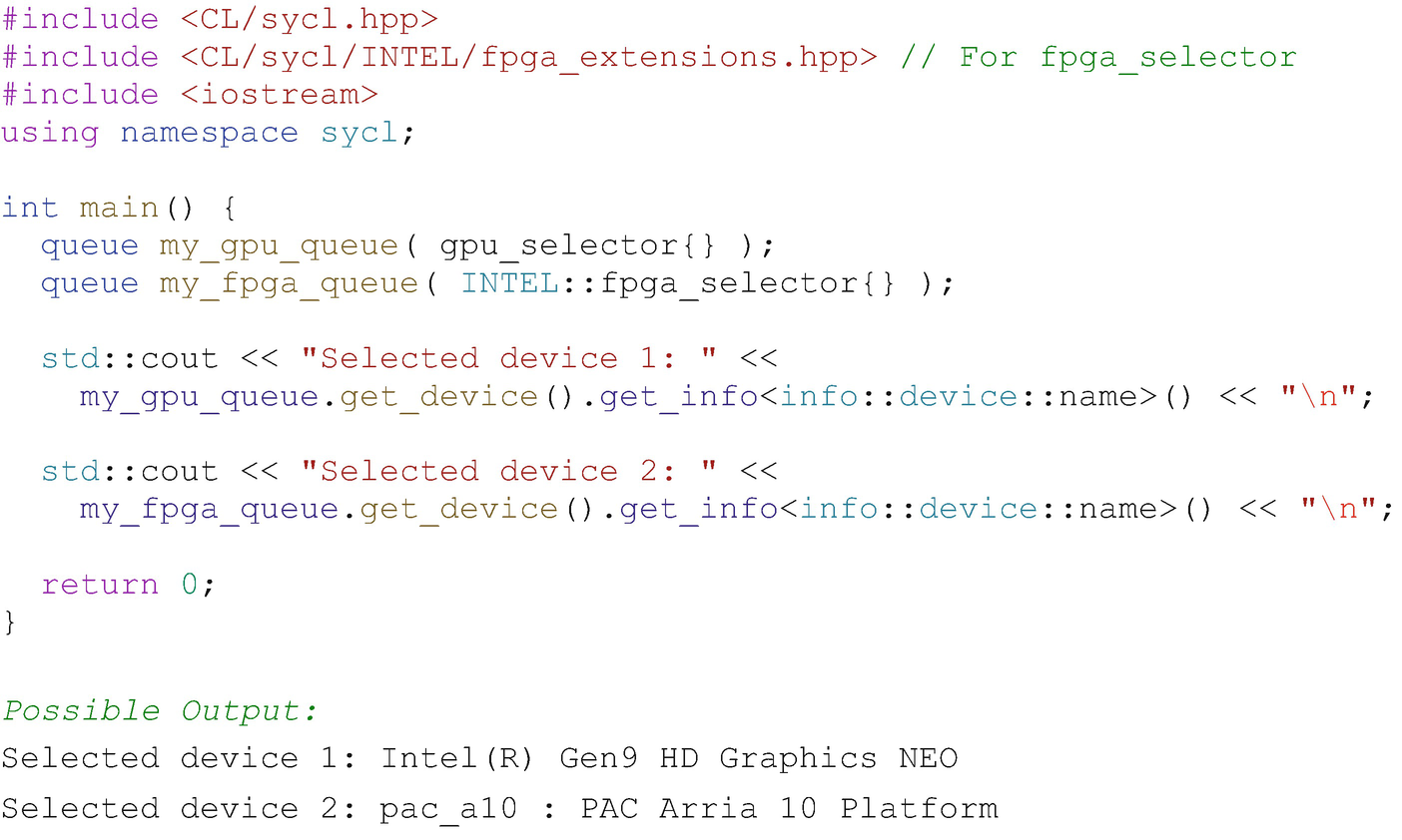
Creating queues to both GPU and FPGA devices
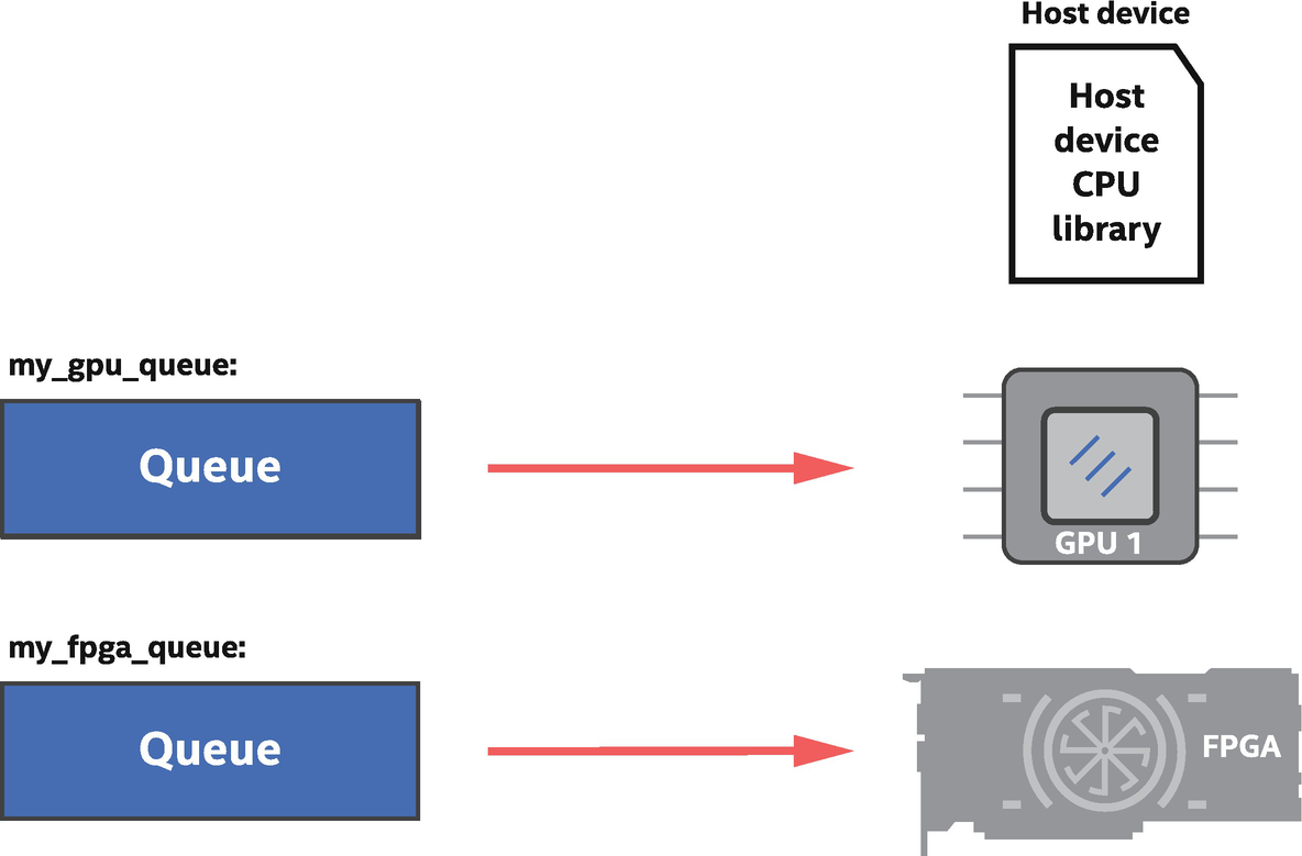
GPU + FPGA device selector example: One queue is bound to a GPU and another to an FPGA
Method#5: Custom (Very Specific) Device Selection
We will now look at how to write a custom selector. In addition to examples in this chapter, there are a few more examples shown in Chapter 12. The built-in device selectors are intended to let us get code up and running quickly. Real applications usually require specialized selection of a device, such as picking a desired GPU from a set of GPU types available in a system. The device selection mechanism is easily extended to arbitrarily complex logic, so we can write whatever code is required to choose the device that we prefer.
device_selector Base Class
All device selectors derive from the abstract device_selector base class and define the function call operator in the derived class:

- 1.
The function call operator is automatically called once for each device that the runtime finds as accessible to the application, including the host device.
- 2.
The operator returns an integer score each time that it is invoked. The highest score across all available devices is the device that the selector chooses.
- 3.
A negative integer returned by the function call operator means that the device being considered must not be chosen.
Mechanisms to Score a Device
- 1.
Return a positive value for a specific device class.
- 2.
String match on a device name and/or device vendor strings.
- 3.
Anything we can imagine in code leading to an integer value, based on device or platform queries.
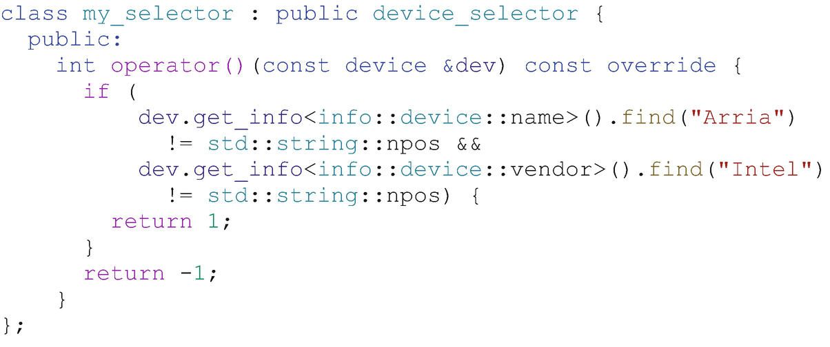
Custom selector for Intel Arria FPGA device
Chapter 12 has more discussion and examples for device selection (Figures 12-2 and 12-3) and discusses the get_info method in more depth.
Three Paths to Device Code Execution on CPU
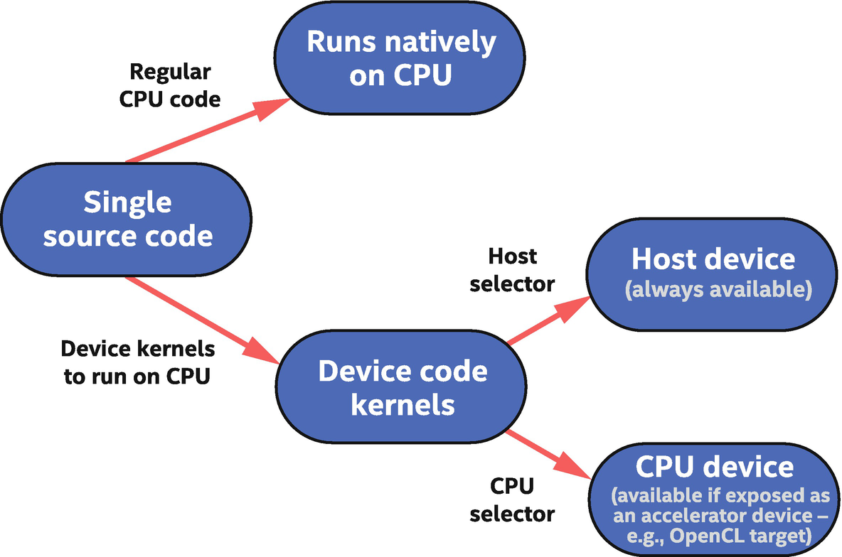
SYCL mechanisms to execute on a CPU
The first and most obvious path to CPU execution is host code, which is either part of the single-source application (host code regions) or linked to and called from the host code such as a library function.
The other two available paths execute device code. The first CPU path for device code is through the host device, which was described earlier in this chapter. It is always available and is expected to execute the device code on the same CPU(s) that the host code is executing on.
A second path to execution of device code on a CPU is optional in SYCL and is a CPU accelerator device that is optimized for performance. This device is often implemented by a lower-level runtime such as OpenCL, so its availability can depend on drivers and other runtimes installed on the system. This philosophy is described by SYCL where the host device is intended to be debuggable with native CPU tools, while CPU devices may be built on implementations optimized for performance where native CPU debuggers are not available.
Although we don’t cover it in this book, there is a mechanism to enqueue regular CPU code (top part of Figure 2-16) when prerequisites in the task graph are satisfied. This advanced feature can be used to execute regular CPU code alongside device code in the task graph and is known as a host task.
Creating Work on a Device
Applications usually contain a combination of both host code and device code. There are a few class members that allow us to submit device code for execution, and because these work dispatch constructs are the only way to submit device code, they allow us to easily distinguish device code from host code.
The remainder of this chapter introduces some of the work dispatch constructs, with the goal to help us understand and identify the division between device code and host code that executes natively on the host processor.
Introducing the Task Graph
A fundamental concept in the SYCL execution model is a graph of nodes. Each node (unit of work) in this graph contains an action to be performed on a device, with the most common action being a data-parallel device kernel invocation. Figure 2-17 shows an example graph with four nodes, where each node can be thought of as a device kernel invocation.
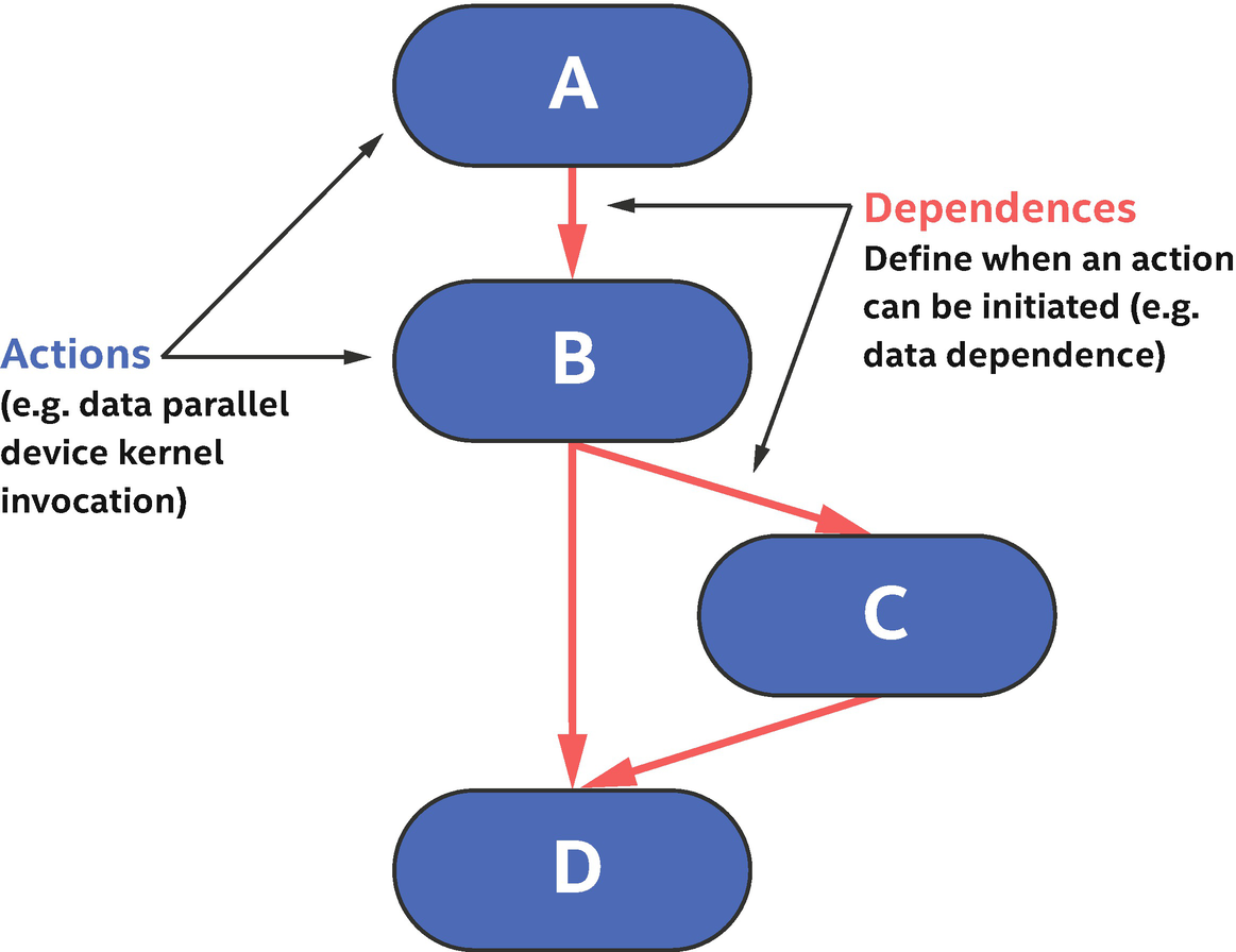
The task graph defines actions to perform (asynchronously from the host program) on one or more devices and also dependences that determine when an action is safe to execute

Submission of device code
Where Is the Device Code?
There are multiple mechanisms that can be used to define code that will be executed on a device, but a simple example shows how to identify such code. Even if the pattern in the example appears complex at first glance, the pattern remains the same across all device code definitions so quickly becomes second nature.

Simplified definition of member functions in the handler class
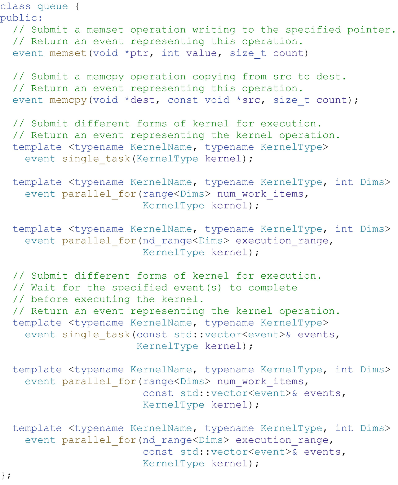
Simplified definition of member functions in the queue class that act as shorthand notation for equivalent functions in the handler class
Actions
- 1.
Exactly one call to an action that either queues device code for execution or performs a manual memory operation such as copy.
- 2.
Host code that sets up dependences defining when it is safe for the runtime to start execution of the work defined in (1), such as creation of accessors to buffers (described in Chapter 3).
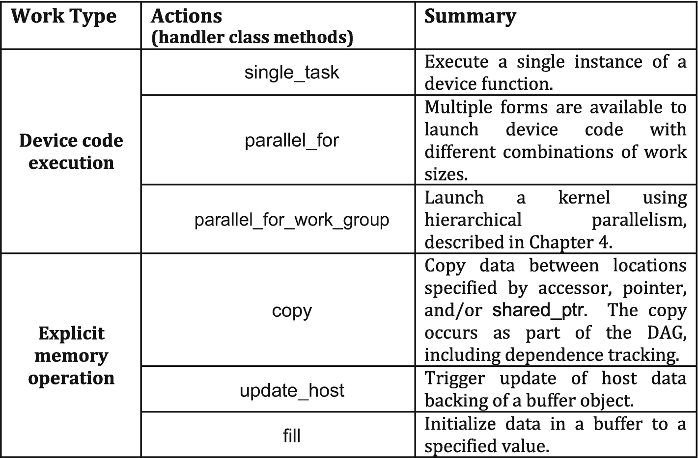
Actions that invoke device code or perform explicit memory operations
Only a single action from Figure 2-21 may be called within a command group (it is an error to call more than one), and only a single command group can be submitted to a queue per submit call. The result of this is that a single operation from Figure 2-21 exists per task graph node, to be executed when the node dependences are met and the runtime determines that it is safe to execute.
A command group must have exactly one action within it, such as a kernel launch or explicit memory operation.
The idea that code is executed asynchronously in the future is the critical difference between code that runs on the CPU as part of the host program and device code that will run in the future when dependences are satisfied. A command group usually contains code from each category, with the code that defines dependences running as part of the host program (so that the runtime knows what the dependences are) and device code running in the future once the dependences are satisfied.
- 1.
Host code: Drives the application, including creating and managing data buffers and submitting work to queues to form new nodes in the task graph for asynchronous execution.
- 2.
Host code within a command group: This code is run on the processor that the host code is executing on and executes immediately, before the submit call returns. This code sets up the node dependences by creating accessors, for example. Any arbitrary CPU code can execute here, but best practice is to restrict it to code that configures the node dependences.
- 3.
An action: Any action listed in Figure 2-21 can be included in a command group, and it defines the work to be performed asynchronously in the future when node requirements are met (set up by (2)).
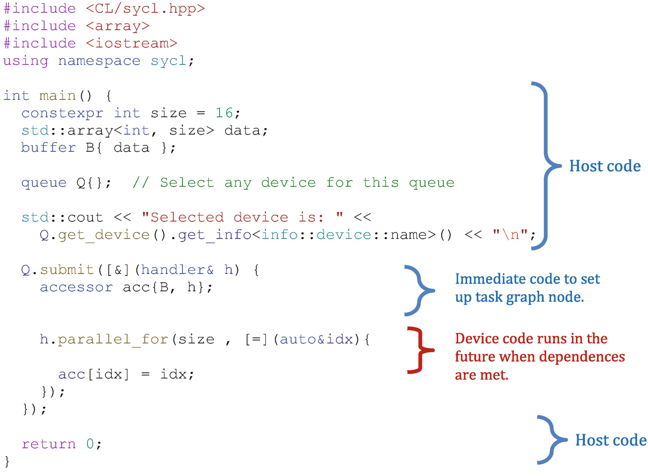
Submission of device code
To understand when code in an application will run, note that anything passed to an action listed in Figure 2-21 that initiates device code execution, or an explicit memory operation listed in Figure 2-21, will execute asynchronously in the future when the DAG node dependences have been met. All other code runs as part of the host program immediately, as expected in typical C++ code.
Fallback
Usually a command group is executed on the command queue to which we have submitted it. However, there may be cases where the command group fails to be submitted to a queue (e.g., when the requested size of work is too large for the device’s limits) or when a successfully submitted operation is unable to begin execution (e.g., when a hardware device has failed). To handle such cases, it is possible to specify a fallback queue for the command group to be executed on. The authors don’t recommend this error management technique because it offers little control, and instead we recommend catching and managing the initial error as is described in Chapter 5. We briefly cover the fallback queue here because some people prefer the style and it is a well-known part of SYCL.
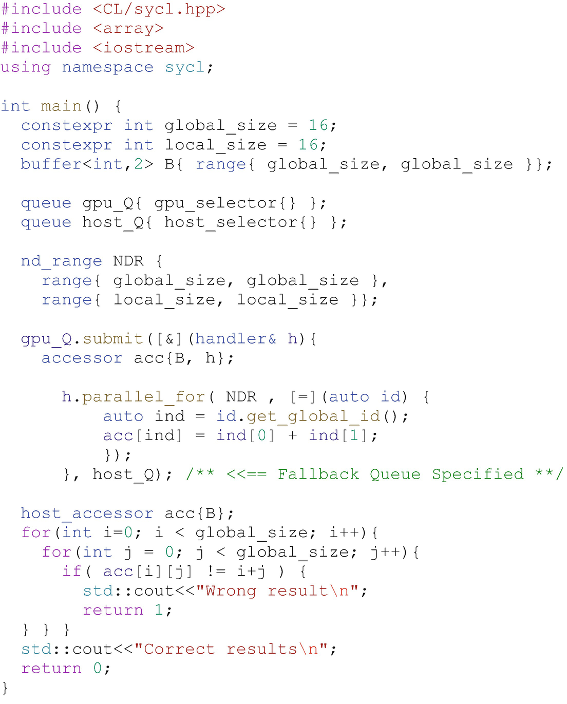
Fallback queue example
The topic of fallback based on devices that are present will be discussed in Chapter 12.
Figure 2-23 shows code that will fail to begin execution on some GPUs, due to the requested size of the work-group. We can specify a secondary queue as a parameter to the submit function, and this secondary queue (the host device in this case) is used if the command group fails to be enqueued to the primary queue.
The fallback queue is enabled by passing a secondary queue to a submit call. The authors recommend catching the initial error and handling it, as described in Chapter 5, instead of using the fallback queue mechanism which offers less control.
Summary
In this chapter we provided an overview of queues, selection of the device with which a queue will be associated, and how to create custom device selectors. We also overviewed the code that executes on a device asynchronously when dependences are met vs. the code that executes as part of the C++ application host code. Chapter 3 describes how to control data movement.

Open Access This chapter is licensed under the terms of the Creative Commons Attribution 4.0 International License (http://creativecommons.org/licenses/by/4.0/), which permits use, sharing, adaptation, distribution and reproduction in any medium or format, as long as you give appropriate credit to the original author(s) and the source, provide a link to the Creative Commons license and indicate if changes were made.
The images or other third party material in this chapter are included in the chapter's Creative Commons license, unless indicated otherwise in a credit line to the material. If material is not included in the chapter's Creative Commons license and your intended use is not permitted by statutory regulation or exceeds the permitted use, you will need to obtain permission directly from the copyright holder.