Boiler.
Once Turbomotive’s construction had been approved the LMS’s Drawing Office at Derby and Metrovick’s Drawing Office in Manchester worked closely together to prepare detailed plans and specifications. Only some of these items have survived the blitz on records, in both organisations, that took place in the 1950s and 1960s as steam gave way to other forms of motive power. In the words of instructions issued on record regarding preservation they are ‘to be retained for the life of the asset’. Luckily some far-sighted people intervened at the time and a number of items have been preserved, in institutions and in private collections. For this reason we can now follow the design process and see how these two technologies were married together and Turbomotive was created.
MODIFICATIONS TO THE PRINCESS
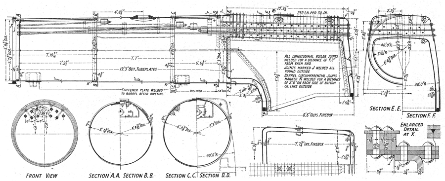
Boiler.
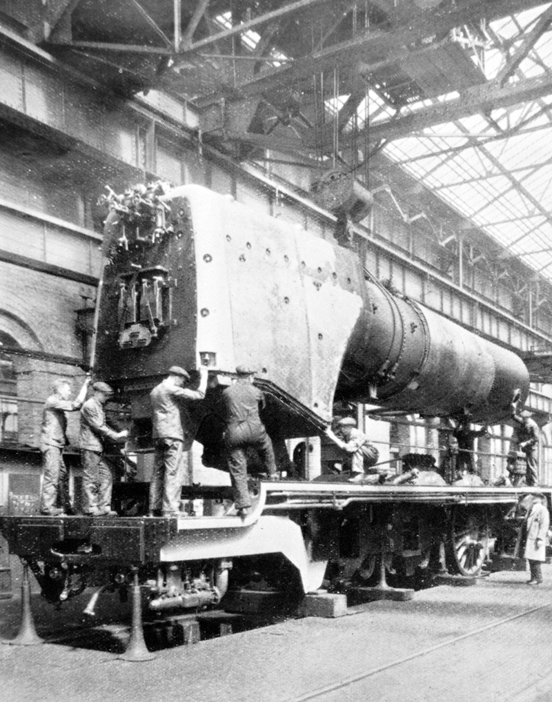
Boiler number 9100 being fitted to 6202’s frames. (RH)
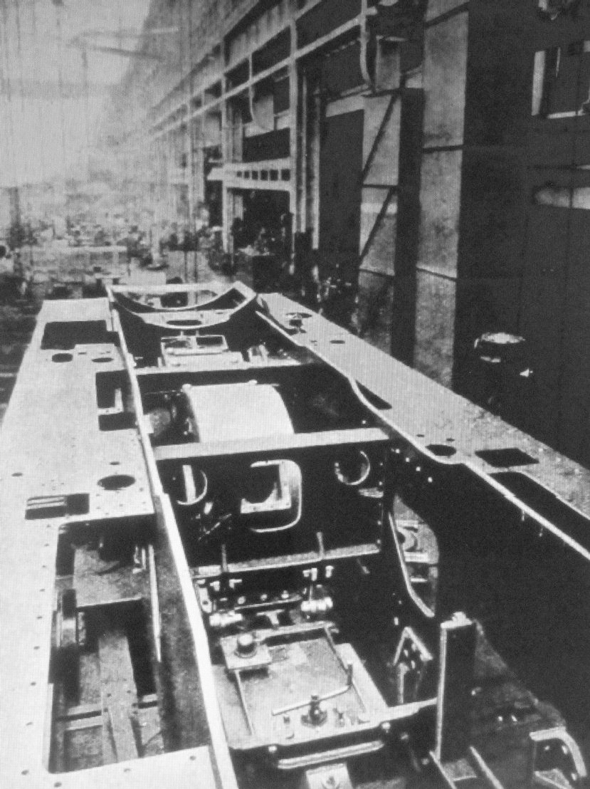
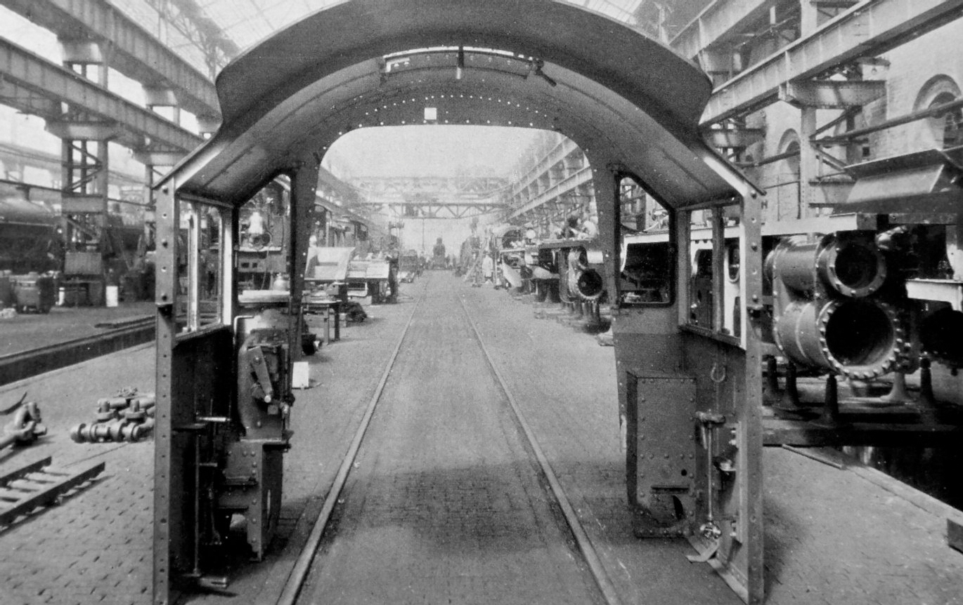
The frames before the boiler was fitted – gear unit in place. (RH)
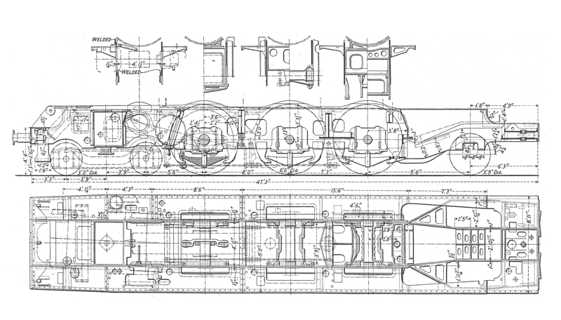
Altered Frame Arrangement.
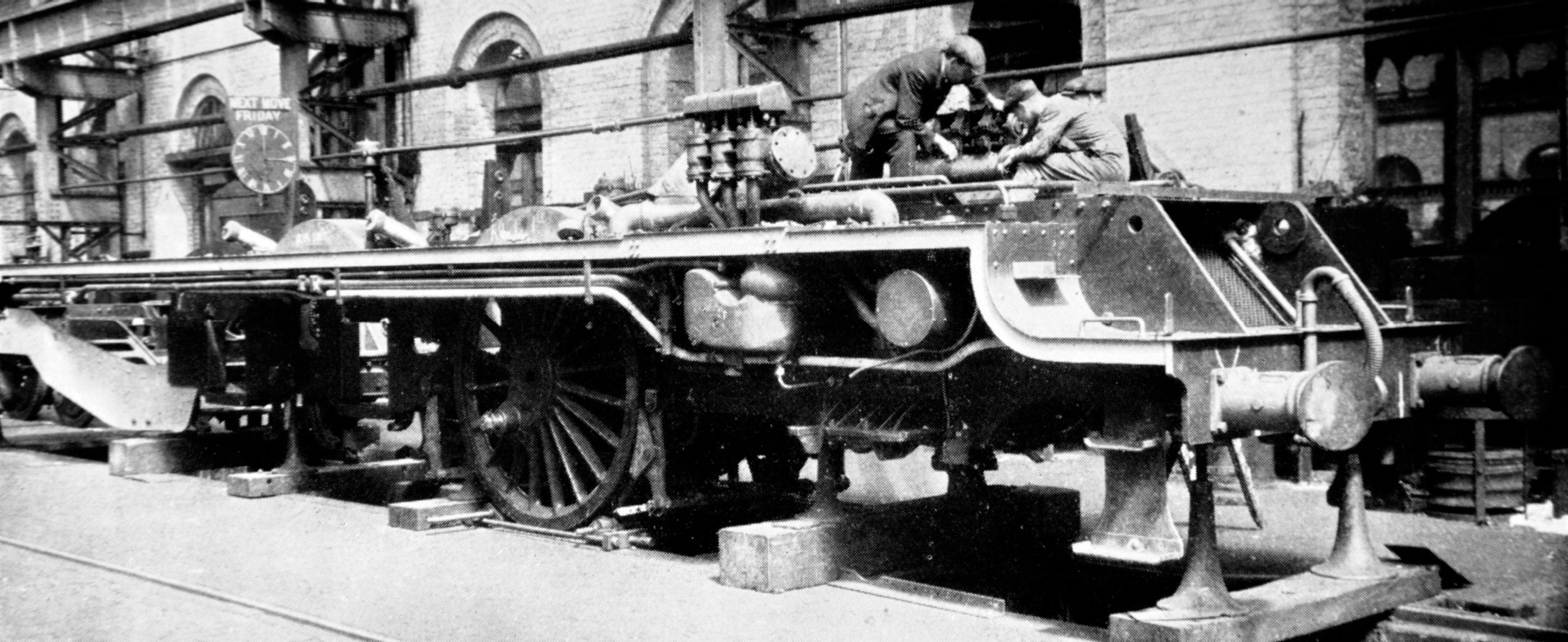
The turbine units and gear box in place. (RH)
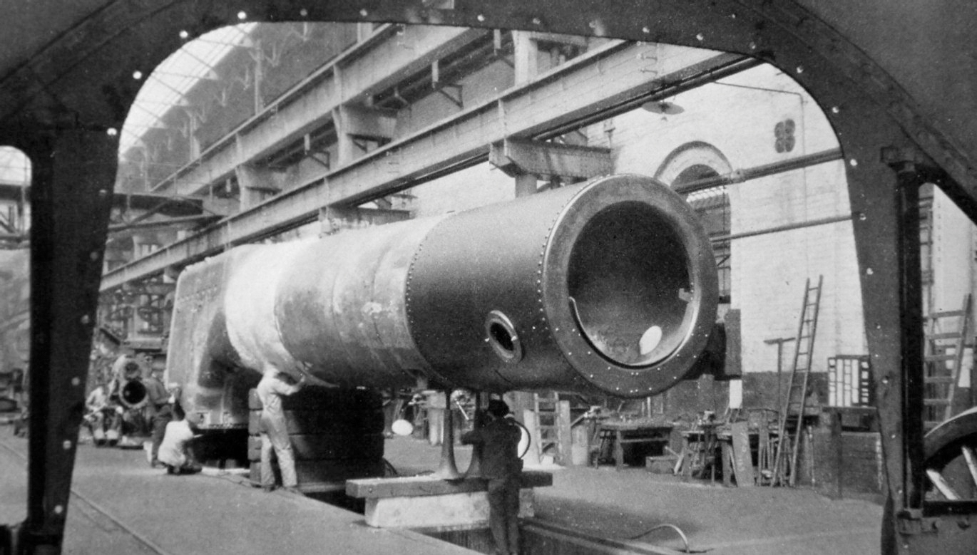
6202’s boiler ready to lifted into her frames. (RH)
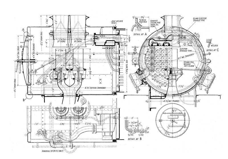
Smokebox Arrangement.
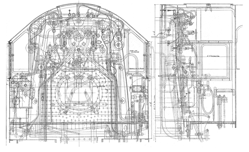
Arrangement of Cab, Fittings and Controls.
6202’s cab waiting to be fitted. (RH)
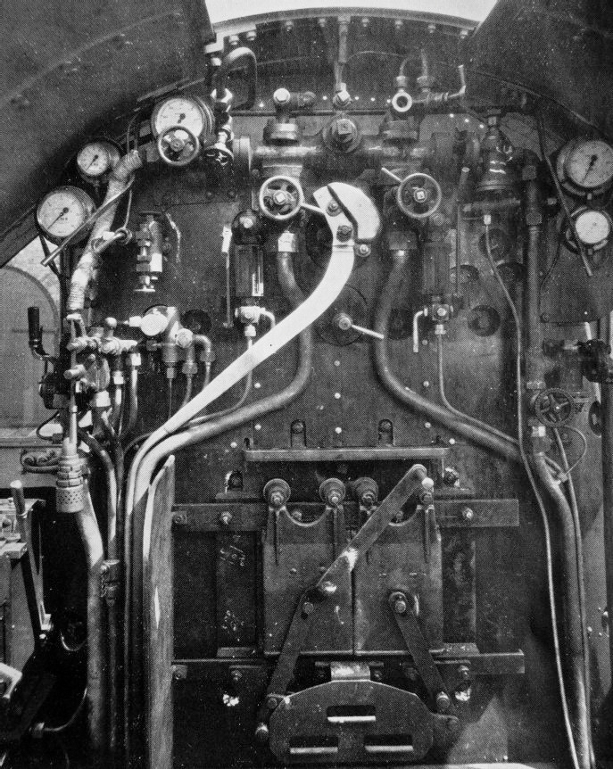
6202’s backhead and cab completed. (RH)
THE TURBINES, GEAR BOX AND ANCILLARY EQUIPMENT
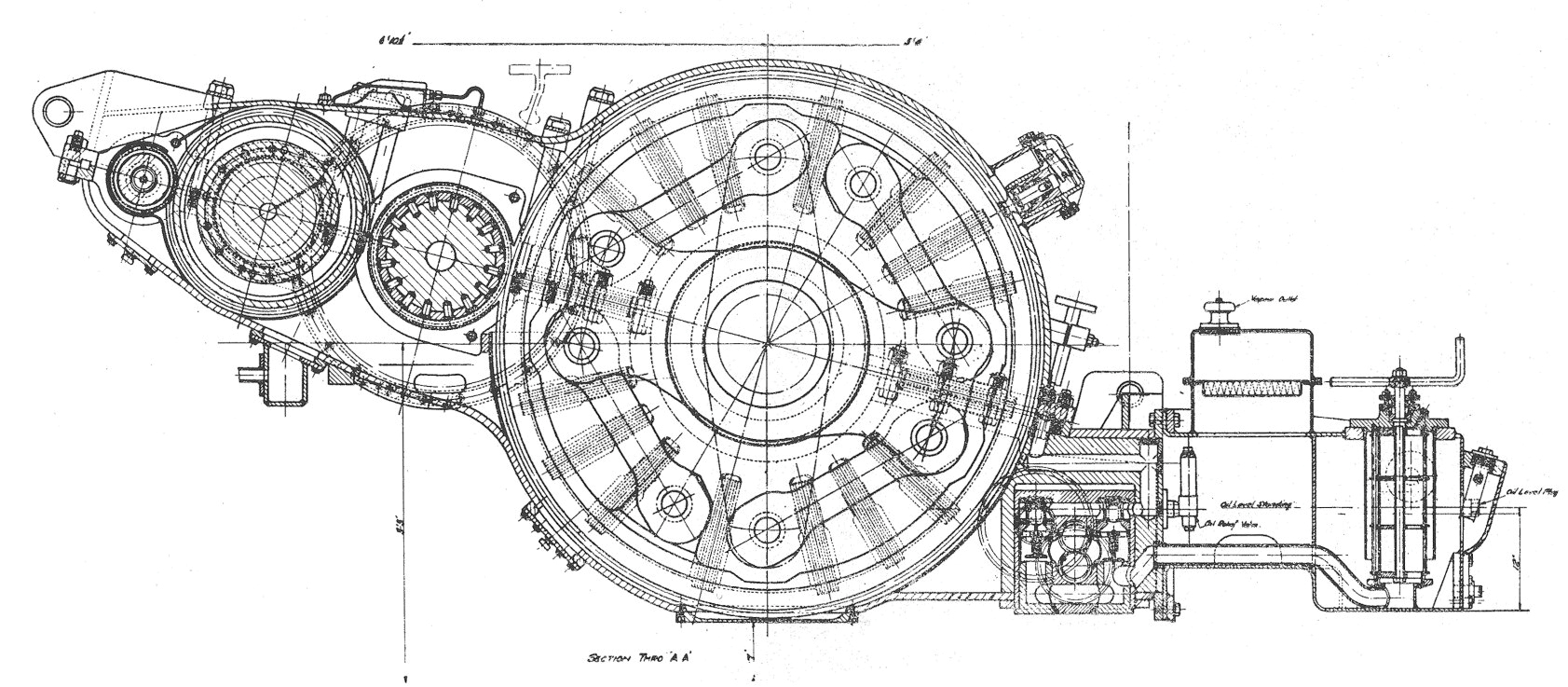
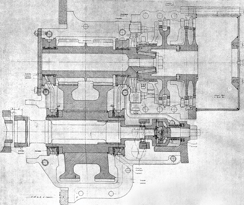
General Arrangement of the Gear Box, Oil Tank and Pump.
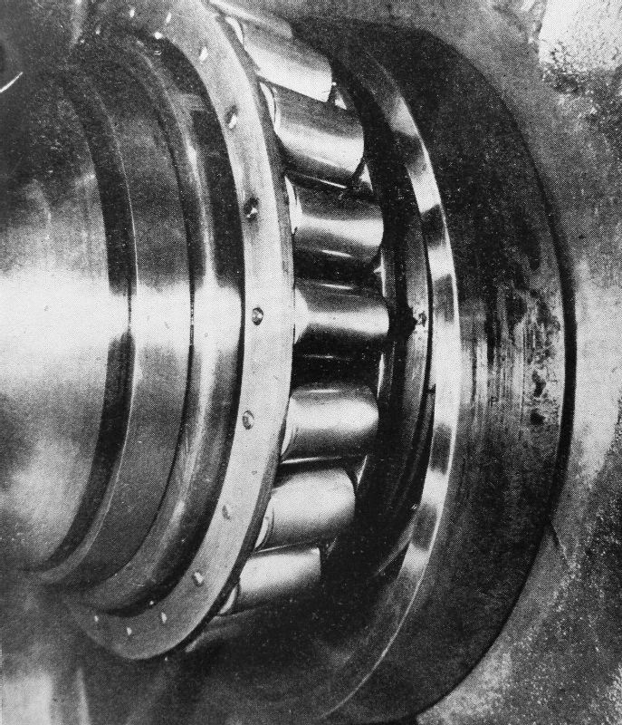
PHOTO:
Timken Roller Bearings were fitted to all wheels on Turbomotive. This picture shows how they appeared with covers removed.
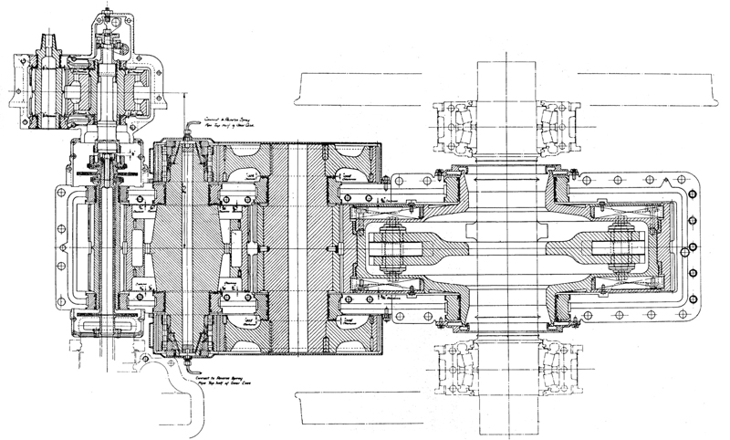
Cross Section - Gear Box, Oil Tank and Pump in place, showing the Timken Roller Bearings in place.
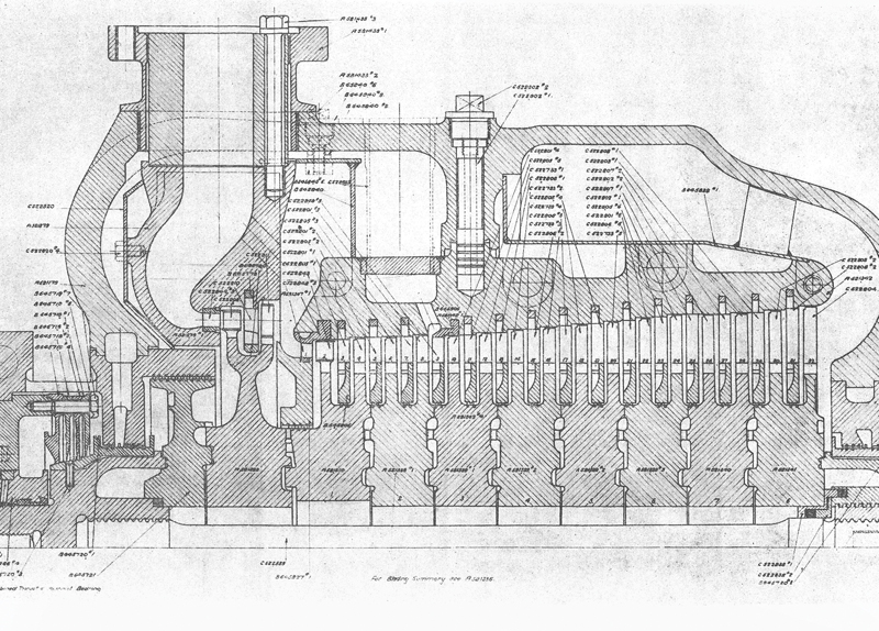
The Forward Turbine Unit.
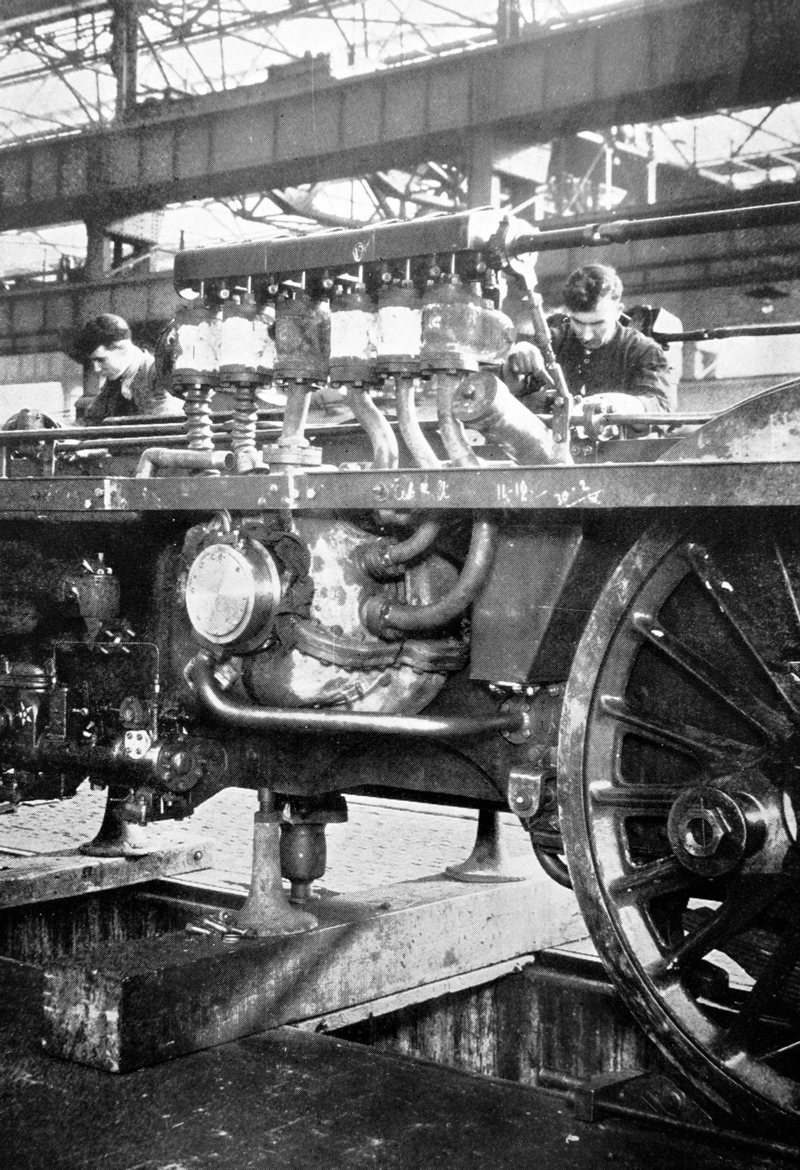
Working on the turbines (forward turbine nearest the camera). (RH)
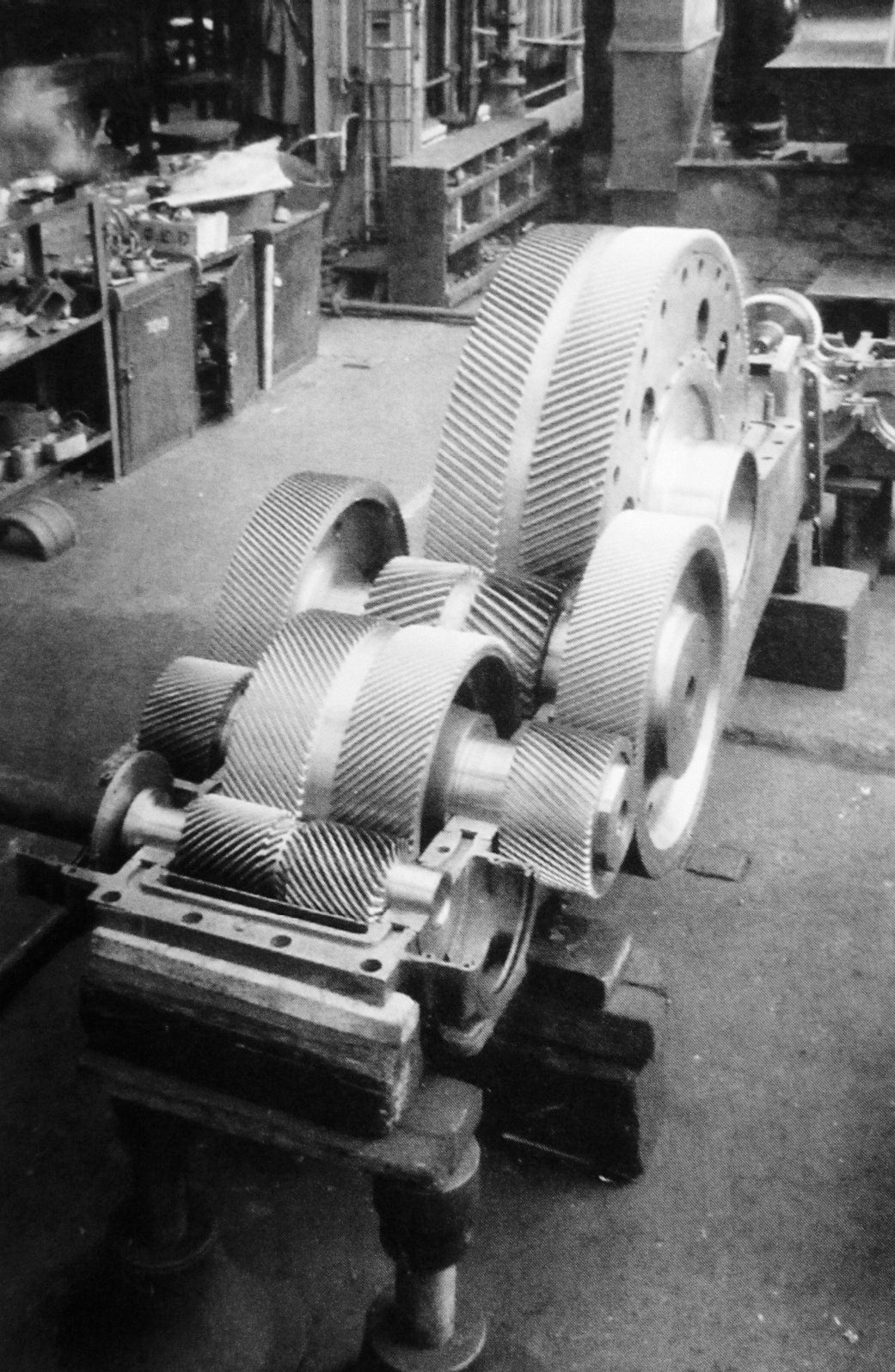
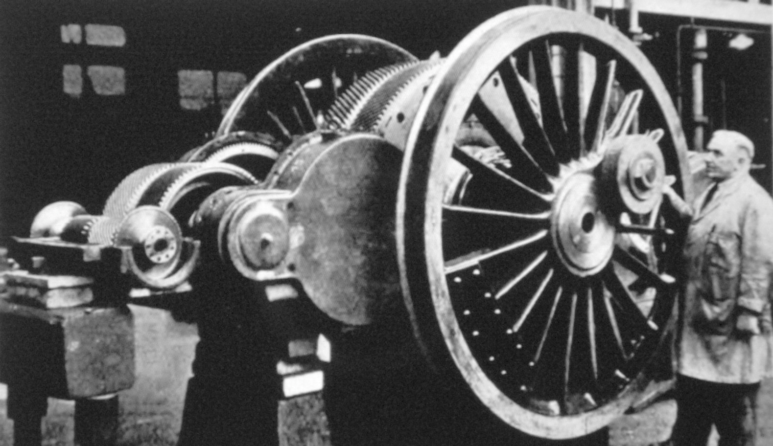
The double helical triple reduction gear and transmission unit (covers removed). (MP) (Taken at Metrovick’s Trafford Park factory)
The Reverse Turbine Unit.
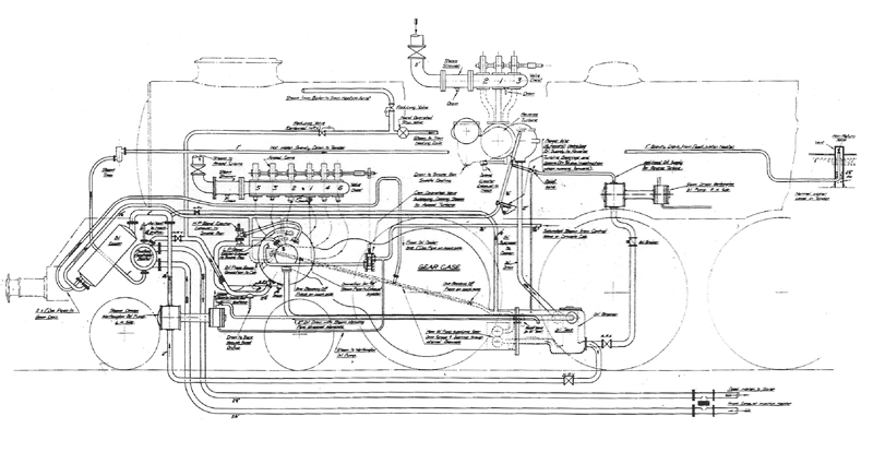
Diagram of Pipe Connections.
The unit fitted to the leading coupled axle before installation in the frames. (RH)
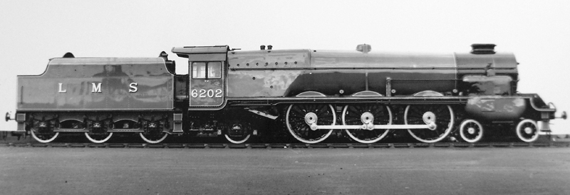
Turbomotive – an early publicity photo. (RH)
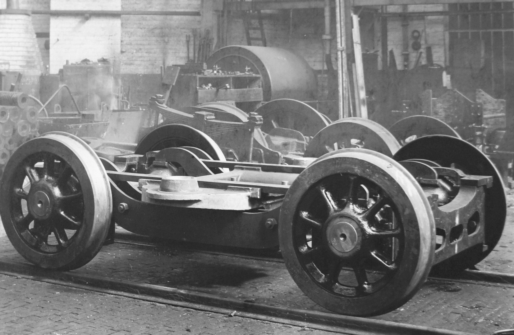
6202’s leading bogie. (AE)
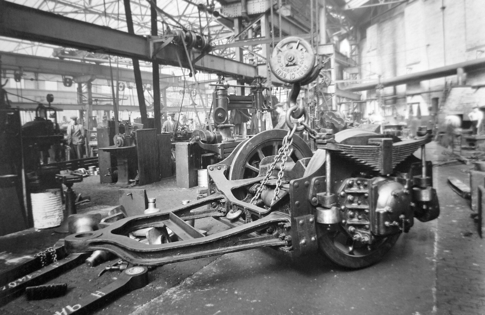
6202’ s trailing bogie. (AE)