It is a basic tenet of engineering that no machine will go through life without undergoing modification or refinement, particularly if it is experimental. From outline design, through detailed specification to construction, then in service, a machine undergoes change as problems are discovered, the requirement changes or new ideas are proposed. Turbomotive’s life was a constant process of modification and refinement and this appendix sets out how this engine evolved from the first tentative drawings, prepared following William Stanier and Henry Guy’s visit to the Ljungstrom Works in Sweden, to its 1952 reconstruction. No detailed workshop files or records seem to have survived for 6202, as is the case for most other steam locomotives, so what follows will be incomplete.
An Evolution Captured in Drawings
6202 closely followed the design of her two experimental sisters, 6200 and 6201. The drawing offices at Derby and Metrovick in Manchester took the initial Princess plans and modified the shape and structure to allow the turbines, gears and ancillary equipment to be fitted. In seeking LMS Board approval to construct this third, radically different engine, an outline specification and drawing were produced as part of the justification paper.
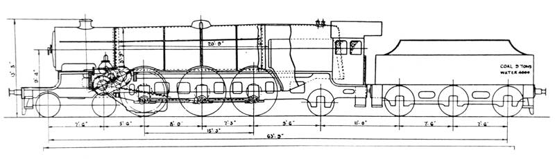
1933 – DRAWING AND SPECIFICATION
Specification for Proposed 2600hp Turbine Locomotive System Ljungstrom
Diameter of wheels – 6’ 9’’
Grate area – 45sq ft
Steam pressure – 250lbs Steam supply to prime mover – 30,000Ibs
Total temp – 850F
Heating surface total – 2,100 sq ft
Weight on drivers – 68 metric tons
Max speed – 90mph
Overall length over buffers – 74’3’’
Wheel base length – 63’ 10’’
Turbine performance
• at starting to produce tractive effort of 40,000Ibs plus
• at 70mph 12,000Ibs plus
• the turbine will be designed for max efficiency at 60mph (at which the turbine will rotate at 760rpm)
• at 90mph the max speed of the turbine will be 10,220rpm (sub-note in Ljungstrom’s brief: ‘the turbine will be capable of an rpm higher than this with speeds in excess of 90mph. Road and static tests will identify the locomotive’s potential’).
Turbine construction
• the turbine will drive through a double reduction gear, a gear wheel coupled to the driving axle (of the front driving wheels). A separate reversing turbine will be provided that drives the main turbine highspeed pinion through a wheel clutch and an additional reducing gear.
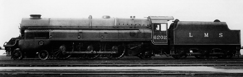
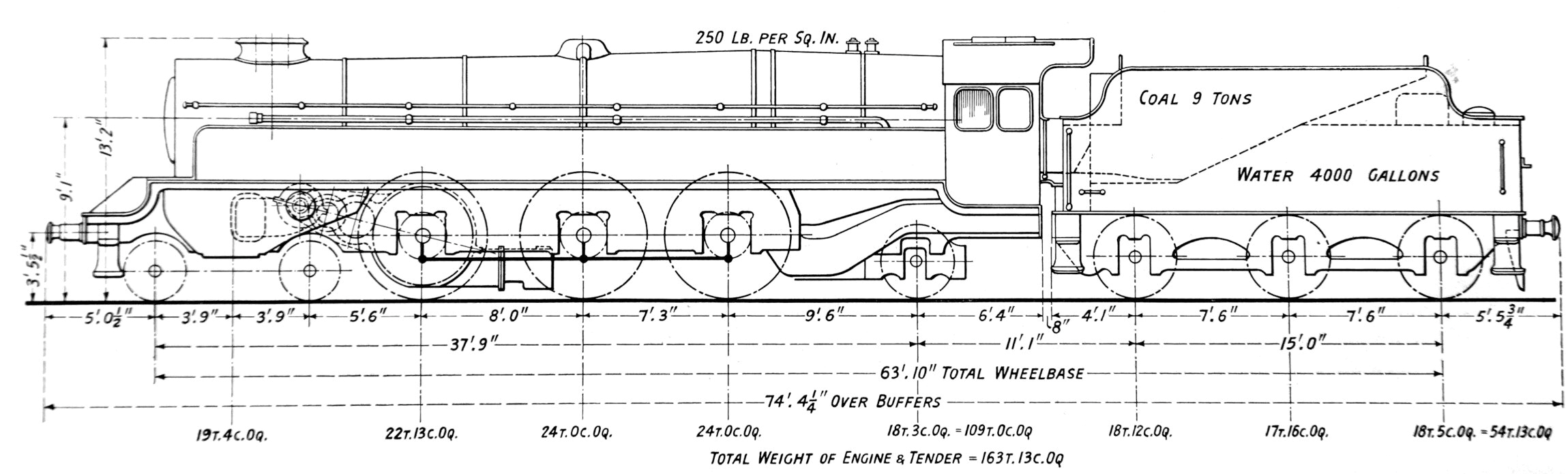
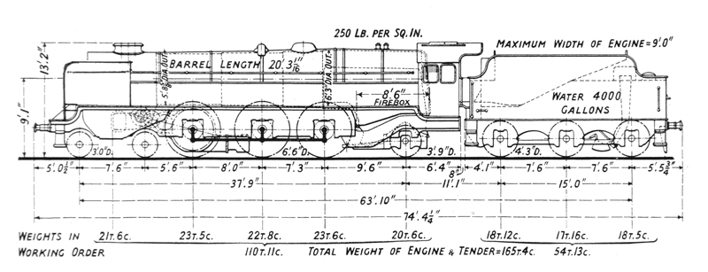
1935 – 6202 AS CONSTRUCTED
Supplementary Information
Diameter of wheels – 6’ 6’’
Boiler – Type 1 Belpaire taper (No 9100)
Total temp – 750F
Chimney fitted – double blast-pipe
Max speed – 90mph
Tractive power at 85% – 40,300Ibs
Tender fitted – No 9003
• Forward turbine – this power unit comprises a multistage turbine and treble reduction gear, bolted to the left-hand side of the frames. Steam from the boiler is fed to a steam chest, which contains six control valves operated by the footplate crew in the cab. The speed of the turbine is controlled by opening these control valves progressively, steam exhaust exiting through the smoke box. The final drive ratio for the forward turbine was 34.4 to 1.
• Reverse turbine – this unit is of the impulse type with an additional single reduction gear, the wheel shaft of which is in line with the high-speed pinion of the main gear. For reverse running, this wheel shaft is coupled to the main gear by a mechanical clutch operated from the cab. This turbine is bolted to the loco’s right-hand frame and had a final drive ratio of 77 to 1.
• Wheel bearings – Timken roller bearings and axle boxes fitted to all the locomotive and tender wheels – four different designs incorporated to meet the individual conditions imposed on each axle/wheel by their position and purpose on the loco and tender.
Suppliers of Components and Material for 6202
• Turbines, transmission gear, control valves and so on – Metropolitan Vickers of Manchester.
• Exhaust steam injector (right-hand side) – Davies & Metcalfe Ltd of Stockport.
• Live steam injector (left-hand side) – Gresham & Craven Ltd of Salford & Manchester.
• Axlebox roller bearings (engine and tender) – British Timken Ltd of Birmingham.
• Steam pump for oil cooling circulation – Worthington-Simpson Ltd of London.
• Steel boiler plates for barrel and firebox wrapper (2 per cent nickel steel) – Colvilles Ltd of Motherwell.
• Superheater apparatus – The Superheater Company Ltd of Manchester.
• Monel metal firebox stays – Henry Wiggins Ltd of Birmingham.
• Buffers – Geo. Turton, Platts & Co Ltd of Sheffield.
• Insulating materials for boiler, firebox, turbines, control valves and piping – Alfol Insulation Co Ltd of London.
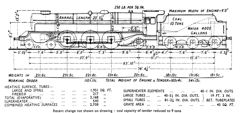
1936 – MODIFICATIONS
Major Modifications Carried Out in 1936
• Boiler – the original boiler only produced a steam temperature of approximately 620 F, against a specification of 750 F, and this was not deemed sufficient for truly effective running. So in July 1936 a new 40 element domed boiler (No 9236) was fitted. This change pushed the steam temperature up to approximately 685 F.
• Reverse turbine – during the first few months of operation, the reverse turbine performed poorly. To improve performance, it was redesigned to increase its power and efficiency. Other modifications were undertaken at the same time to eliminate the causes of breakdowns:
• The clutch and turbine steam valves were interlocked to prevent the valves being opened until the clutch was fully engaged.
• The steam reversing cylinder was replaced by a hand-operated screw arrangement on the control box in the engine’s cab.
• The turbine thrust bearing surfaces were increased in area and the lubricating arrangements improved.
• A visual indicator was attached to the clutch so that its operation could be checked.
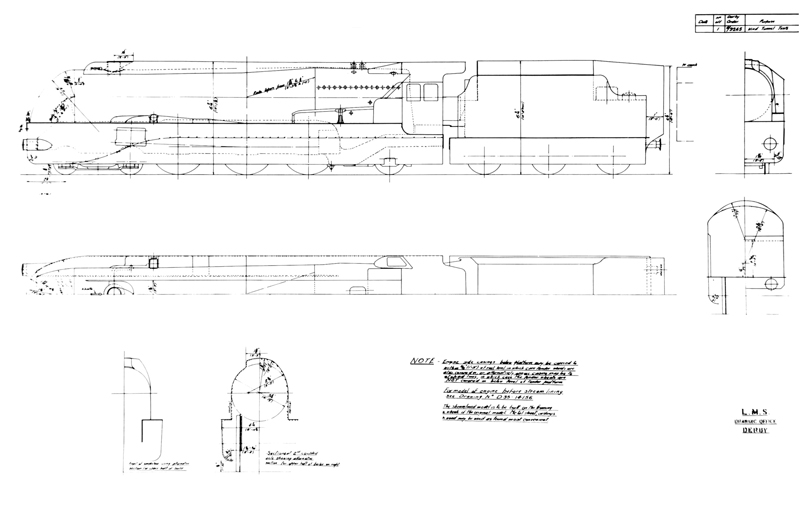
1936 – STREAMLINING PROPOSAL
The success of Nigel Gresley’s streamlined A4s, supported by similar developments elsewhere in the world and F.C. Johansen’s experimental work at the National Physical Laboratory and the Research Department at Derby, proved an attraction to the LMS Board. This work would eventually have the biggest impact on the building of the new Coronation Class, but proposals were floated to include all the Princesses as well. Derby Drawing Office produced a series of plans showing how this need might be met. Subsequently wooden models were produced so that wind tunnel tests could be undertaken to establish the most effective streamlined shape. Nothing came of this work, but in this drawing we are left with a tantalising glimpse of the way 6202 and her sisters might have looked if the work had gone ahead.
1937-1950 – MODIFICATIONS
• Smoke deflectors – drifting smoke obscuring the forward view from the cab was a constant problem. To improve visibility smoke deflectors were fitted in July 1939, shaped around the casing containing the steam supply, nozzles, piping and controls.
• Reverse turbine – an additional Worthington pump fitted to improve oil supply to this turbine unit (1941), following failure. At the same time the left-hand side casing was extended towards the cab (but did not mirror the full-length casing on the right-hand side).
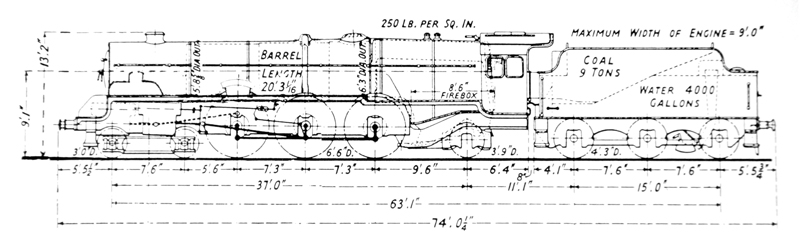
1952 – RECONSTRUCTION
Major reconstruction was authorised under Job No 5621, with all drawings for the ‘new’ engine undertaken at Derby. Work was completed at Crewe in August 1952. The major elements of this task were:
• Frames – Turbomotive’s frames were built differently to her sister engines, so that turbines and gears could be accommodated. Reconstruction necessitated major changes to the frames to allow four cylinders, of the Coronation type, and other equipment to be fitted. Front sections were cut away and new sections welded to the remains, with spacing between leading and intermediate coupled wheels reduced to 7’ 3’’. The frame stretchers, boiler carrier, steam pipes, smoke box saddle, outside motion plate, sandbox and extension pipes, sand shields and buffer beam were all redesigned and modified.
• Boiler – boiler number 9236 was refitted to the engine (having been attached to 46204 from 1950 to 1952 while 46202’s future was under consideration). Its internal layout was altered with 101 small tubes and 9swg trifurcated elements being fitted, giving a tube heating surface of 2,232sq ft and a superheated surface of 720sq ft. A new smoke box and single chimney were also fitted. Coronation-style outside steam pipes to all four cylinders were installed, sheathed in bulbous casings either side of the smoke box.
• Cylinders/Valves/Motion – layout of the cylinders and Walschaerts valve gear to the Coronation design, with the outside cylinders between the bogie wheels. Only the outside valve gear was used, the inside sets being driven by rocking levers behind the cylinders. The eccentric rods were fitted with ball bearing ends to the return cranks.
• Cab/Wheels/Tender – the cab underwent minor modifications to allow it to house the control layout of a reciprocating engine. The 6’ 6’’ size driving wheels were retained and refurbished. The original tender, number 9003, was reattached to the engine when reconstruction was completed.