CHAPTER 27
The Breathing Circuit
Introduction
It is exceedingly important for anesthesia personnel to understand and become proficient at using the several breathing apparatuses with which they will be working. Fortunately, anesthesia breathing systems represent very simple and logical devices and are consequently quite easy to learn. For the purpose of this chapter, anesthesia breathing apparatuses are defined as devices that enable the ability to deliver a defined gas or vapor (including air or oxygen). It should be noted that this discussion does not include anesthesia machines, with which one can control the component gases delivered, nor does it include ventilators that assist breathing but are not considered the actual breathing apparatus; those topics are discussed in Chapters 24 and 28, respectively. This chapter focuses on the development of anesthesia breathing systems from a functional perspective.
Fundamental Requirements
Understanding both the function and design of breathing circuits can be accomplished by rote memorization of the various circuit designs, and is often illustrated by describing the history of their development. I recommend learning these devices, however, by first understanding them in their simplest forms and then modifying them to serve more complicated functions. With each modification, one can visualize advantages and disadvantages. Memorization of a variety of circuits will be less useful to the anesthesia provider or technician than understanding the basic principles of what the circuits you use do and how.
One very straightforward breathing apparatus is the snorkel. Let’s start by imagining Tarzan as he hides from his foe in a pond using a hollow reed to breathe (Fig. 27.1).
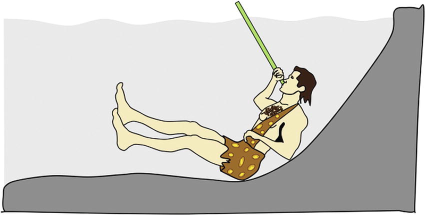
FIGURE 27.1. Avoiding capture by utilizing a hollow reed as a very simple breathing apparatus.
Today’s average snorkel is about 50 cm in length, with an internal diameter of 2 cm, resulting in a capacity, or dead space, of about 150 mL (Fig. 27.2). Although simple to use and understand, snorkels suffer from two limitations: (1) as you decrease the diameter of the breathing tube, there will be significantly increased resistance to breathing (try breathing through a soda straw for any length of time) and (2) as you increase the volume of the breathing tube by increasing either its internal diameter or the length of the breathing tube, it increases the dead space in the breathing system. Imagine Tarzan diving deep to elude gunfire, breathing through a very long reed with an internal diameter of 7.0 mm (the average internal diameter of an adult endotracheal tube); he could descend to 15 feet with the same volume in the reed that our typical snorkel uses, but with greater resistance to airflow, requiring more effort.
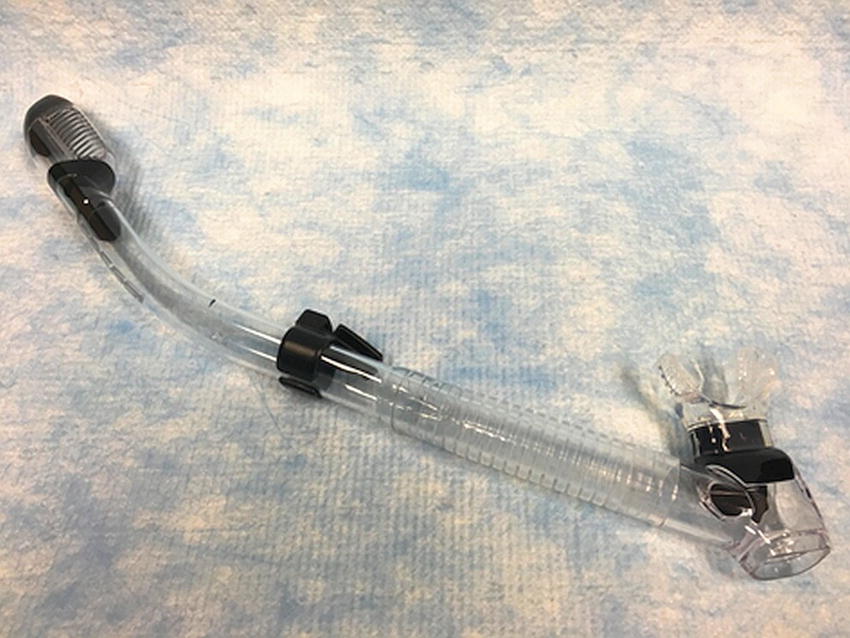
FIGURE 27.2. A modern snorkel.
Dead space in a breathing circuit is the volume of gas that needs to be removed from the system before fresh gas can be exchanged.
Imagine that Tarzan is breathing with a tidal volume of 500 mL (volume of each breath). As Tarzan exhales through the 150 mL snorkel, it fills with exhaled breath until it is flushed out at the end. Just before Tarzan inhales his next breath, the 150 mL volume of the snorkel (dead space) is still filled with the last of the previous exhaled breath. When Tarzan begins to inhale, his first 150 mL is that previously exhaled breath, depleted of oxygen and containing high levels of carbon dioxide (CO2). The next 350 mL inhaled will be fresh tropical air. This 350 mL is plenty of fresh air for Tarzan to survive. Now imagine that Tarzan, being Tarzan, wants to dive deeper to explore the pond or hunt for fish and is using a hose that is 30 feet long and 1 cm in diameter. The dead space of the snorkel is now 600 mL. If Tarzan were to exhale a 500 mL breath, it would fill the snorkel, and then he would breathe back his exhaled breath from the dead space in the snorkel and not get any fresh air! A large dead space would prevent Tarzan from breathing fresh air. The exhaled gas in the dead space contains residual oxygen and large amounts of CO2. Rebreathing the gas from the dead space would rapidly prevent Tarzan from eliminating any CO2 from his lungs. For a short period of time, he could utilize the residual oxygen that he exhales and reinhales. However, if Tarzan were to continue to breathe through this system with a large dead space, he would rapidly become hypercarbic and hypoxic.
Fortunately, Tarzan was creative and quite clever. When he wanted to dive deep, he discovered a way that he could breathe quite comfortably through a reed that was very, very long and sufficiently wide, even though it contained a tremendous dead space. Tarzan utilized his tongue and palate as a one-way valve. He was able to inhale an unlimited supply of fresh air through the wide diameter reed and then exhale expired air through his nose, which bubbled to the surface. Consequently, there is no dead space and no rebreathing. The same thing can be accomplished mechanically by adding a one-way valve to any breathing tube. This modification effectively converts an open breathing system to a semiopen breathing system. This is also what is done when you change from breathing air from the atmosphere, through a snorkel, to breathing air from a tank, using a self-contained underwater breathing apparatus (SCUBA). The valve allows inspired air to flow into the lungs and then diverts exhaled air into the water.
Think of this in terms of the operating room, however, and you discover that all of the exhaled air is polluting the room and potentially anesthetizing everyone hard at work. If Tarzan wanted to get really clever and avoid bubbles in the water he was trying to swim in, he could use a second reed and, still using his mouth as a one-way valve, exhale through the second reed. This would send all of his exhaled breath to the surface without bubbles effectively creating a semiclosed breathing system and avoiding the pollution of his surroundings (telltale bubbles in the pond).
For any breathing apparatus to be effective, the following critical elements are needed:
1. A reservoir: A sufficiently large reservoir of inhaled gas (air, when snorkeling) is needed to expand the lungs with minimum effort. This means that the reservoir of gas or air must be within a very compliant system, allowing it to be easily drawn into the lungs without resistance regardless of the volume inhaled. When using a snorkel, there is a virtually unlimited supply of air above the water. The atmosphere serves as an extremely compliant reservoir of air, which is pulled directly into the breathing tube. No matter how much you inhale, the negative pressure needed does not change. When using air from pressurized tanks, there is virtually no resistance to inhaling as long as the valves are functioning optimally, and the pressure in the tanks is greater than one atmosphere.
2. Low resistance to breathing: The conduits of the breathing apparatus (the route of the air to you) must be of sufficient diameter to conduct the gas being breathed, without creating significant resistance and excessive work of breathing.
3. Low dead space, or another mechanism to effectively prevent rebreathing of exhaled gases: This prevents rebreathing any unwanted exhaled gases (CO2 or anesthetic agents) and provides fresh gas replenished with oxygen. A snorkel contains a dead space of less than 150 mL (much less than a normal adult tidal volume). Alternatively, adding a one-way valve will prevent rebreathing of CO2, by diverting exhaled gases from reentering the breathing tube. This modification converts an open breathing system into a semiclosed breathing system. The advantage is that it effectively eliminates dead space in the breathing system. The major disadvantage of a semiclosed system is contamination of the local environment into which the gases are exhaled. Other disadvantages are that any mechanical valve will add some resistance to breathing, and any mechanical device, regardless of how simple, will ultimately malfunction, that is, become stuck in either the open or the closed position.
Anesthesia Breathing Circuits
In order to effectively design any device, one must identify the ideal goals, evaluate the theoretical limitations of the device or modifications being proposed, and make appropriate accommodations to meet the need. This is what occurred historically in the development of breathing devices used in anesthesia; devices were designed to meet specific needs. The Tarzan example describes the simplest solution to his very simple problem and introduces the concept of a breathing apparatus. Unfortunately, the additional needs to deliver anesthetic agents or permit positive pressure ventilation were addressed in parallel by different people, rather than having everyone starting with a specific design and then improving upon it. The goal is to deliver known mixtures of gases and vapors (e.g., oxygen and anesthetic agents) from a source of gas (often under pressure) and vapor from an anesthesia machine. To focus on the design of breathing devices for this purpose, the gas source will be defined as the gas outlet of an anesthesia machine or the gas hose. Since the anesthesia machine itself is presented elsewhere, it will be schematically represented as a box with a small outlet or gas hose protruding from it, labeled “gas source.” Now, based on the basic principles learned above, let’s design a breathing apparatus to anesthetize Tarzan, rather than enable him to breathe underwater.
Rather than inserting the breathing tube into his mouth, the gas is delivered from the breathing tube over his mouth and nose using a mask. We can now analyze the most effective ways to connect this simple breathing apparatus to the gas source (Fig. 27.3).
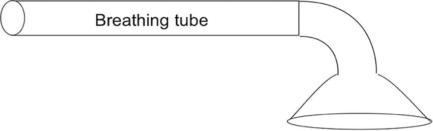
FIGURE 27.3. A simple breathing tube, or snorkel, with an attached mask through which to breathe.
The simplest way to connect the gas source to the breathing tube is to run a smaller diameter gas outlet hose from the “gas source” into the inside of the larger-diameter breathing tube (Fig. 27.4). The gas source could be a large pressurized tank of air, pure oxygen, or an anesthesia machine.
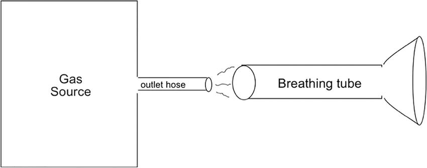
FIGURE 27.4. The source of the gas, or in this case, an anesthesia machine is represented by a box labeled “gas source” with an outlet hose that supplies the gas to the “breathing tube.” Unless the gas outlet hose is placed very deeply into what I have labeled as the breathing tube, and almost to the breathing mask, only room air will be inspired.
The simple system shown in Figure 27.5 can be extremely effective depending on how far into the breathing tube the gas source hose is placed. If the end of the gas hose is placed within the tube and close enough to the breathing mask, the recipient will inhale the gas that had accumulated inside of the breathing tube since the previous exhalation. When the flow of gas is sufficiently high, it will not only be able to supply the lungs with fresh gas during one inhalation breath but can also be utilized to blow out the gas containing high carbon dioxide that has been exhaled on the previous breath. To effectively wash the exhaled gas out of the breathing tube, the flow rate of the fresh gas supplied needs to be at least 1.5-2 times the minute ventilation.
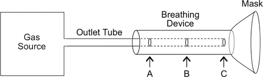
FIGURE 27.5. A simple circuit showing demonstrating various points of fresh gas insertion.
Looking again at Figure 27.5, you can see that the smaller fresh gas source outlet tube can be inserted to different depths into the breathing tube. If the volume contained within the breathing tube is as large as one normally exhaled volume (a tidal volume), when the gas outlet hose is placed only slightly within the breathing tube (to depth A), the patient will primarily breathe exhaled air, perhaps slightly mixed with room air and very little fresh gas from the gas source hose. Advancing the gas supply hose further (to depth B) improves the delivery of the fresh gas and, if the flow is sufficient, helps remove exhaled CO2 by blowing it out of the circuit. Since the dead space in the system, where rebreathing occurs, is the area distal to the end of the gas source hose, including the mask, the optimal placement of the gas source outlet tube is as far into the breathing tube as possible (depth C). When the flow of fresh gas is at least 1.5-2 times the minute ventilation, exhaled CO2 is effectively washed out of the breathing tube, preventing rebreathing and CO2 buildup.
We now have constructed one of the simplest and most effective open circuit breathing apparatuses still used in anesthesiology. It is referred to as a Bain circuit (Fig. 27.7D) and was originally introduced in 1937. Although the breathing apparatus we just designed appears to be the simplest, most logical circuit to develop and one of the most effective open circuits (as it contains no valves), it was not described until after the several less effective configurations, described below, were developed. When configured as described above, the patient breathes spontaneously through the breathing tube and, since it is a completely open system, cannot be ventilated. As you might surmise, the system can be further modified to enable ventilation. A breathing reservoir bag can be added on the end of the breathing tube with a pop-off (adjustable pressure limiting, or APL) valve on the base of the bag. By partially closing the valve on the end of the bag, ventilation can be assisted; this enhances CO2 removal and thus reduces the need for high fresh gas flows to prevent rebreathing. This is commonly known as a Jackson Rees circuit (Fig. 27.6).
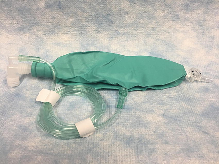
FIGURE 27.6. A Jackson Rees circuit. Notice the small dead space due to the placement of the fresh gas hose.
For historical perspective and completeness, the various breathing circuits as described and analyzed by William Mapleson in 1954 are included in Figure 27.7. Please again note that these circuits were named according to the order of their development, rather than by any logical or intuitive nomenclature. All of them are variations of the very simple circuit first devised by Mapleson in 1954.

FIGURE 27.7. Mapleson circuits, their various modifications and commonly encountered examples.
The described modifications to this simple breathing apparatus involve the relocation of pop-off valves at various positions in the circuit in attempts to reduce rebreathing. Many have largely been abandoned from clinical use in modern anesthesiology. They are mentioned for historical significance; because knowledge of their names and configuration may be deemed important in an examination; and because they are taught to anesthesia residents, so you may hear a circuit referred to a Mapleson type at some point. The Mapleson circuits are shown in Fig. 27.7.
To-Fro System
While the circuits in Figure 27.7, including the modified Ayre T-piece systems, are somewhat effective and efficient, a high gas flow (at least 1.5-2 times the minute ventilation) is necessary to prevent hypercapnia. Although high gas flows may be practical in small children, adults would require fresh gas flows of 10-20 L/min. To maintain such high flows is expensive, inefficient, and produces large amounts of waste gases to be scavenged. One way to reduce both rebreathing and gas flow in the simple system described above is to add a reservoir bag to the end of the tube and manually assist ventilation of the patient. Although this is helpful, it is only moderately effective. Other simple solutions to reduce gas flows and prevent CO2 buildup are to add a CO2 absorber to the system to remove exhaled carbon dioxide, and/or one-way valves, which convert simple open systems to semiclosed systems. CO2 absorbers are further described later in this chapter.
Adding a CO2 absorber to the simple open or semiclosed systems presented above results in what is called a “to-fro” system. The first to-fro canister was developed by Waters to deliver the anesthetic gas cyclopropane. The system is quite effective but results in less than optimal mixing of fresh and expired gases when low flows are used. In to-fro systems, the CO2 absorber may be positioned in various locations relative to the fresh gas source inlet. The example below demonstrates placement of the CO2 canister just proximal to the gas source inlet in a Mapleson F (Jackson-Rees) open system (Fig. 27.8). The exhaled gas is washed through the CO2 absorber, scrubbing the majority of the CO2 from the system leaving the anesthetic gases behind. The next inspiratory breath would utilize that previously exhaled gas and some new gas to make up for what was scrubbed or washed out.
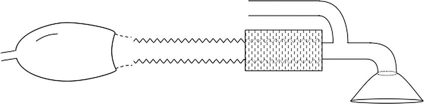
FIGURE 27.8. Addition of a CO2 absorber, in line, to a Mapleson F results in a to-fro system. Note that the distance from the mask to the CO2 absorber is dead space.
Circle Systems
Rather than blowing exhaled gases into the atmosphere at high flow rates, one can reduce gas flow and increase the efficiency of carbon dioxide removal by using a CO2 absorber to remove the carbon dioxide and then directing the exhaled gases back into the breathing system by means of one-way valves. Such changes create what is referred to as a circle system (Fig. 27.9). This is what modern anesthesia machines create in their breathing systems.
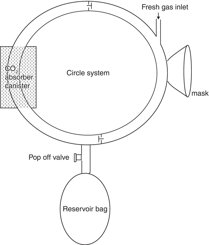
FIGURE 27.9. Circle system. In 1926, Brian Sword developed a unidirectional rebreathing system, referred to as a circle system. The circle system consists of a fresh gas inflow directed to an inspiratory limb and unidirectional valve, an expiratory limb and unidirectional valve, a CO2 absorber, an expiratory pop-off valve, and a reservoir bag. Circle systems may be classified as semiopen, semiclosed, or closed, depending on the amount of fresh gas inflow.
During inspiration, the fresh gas, along with the CO2 in the reservoir bag, flows through the inspiratory limb and its associated unidirectional valve to the patient. During expiration, the inspiratory unidirectional valve closes, and the expired gas flows through the expiratory unidirectional valve in the expiratory limb to the soda lime canister and the reservoir bag. A circuit for a circle system is shown in Figure 27.10.
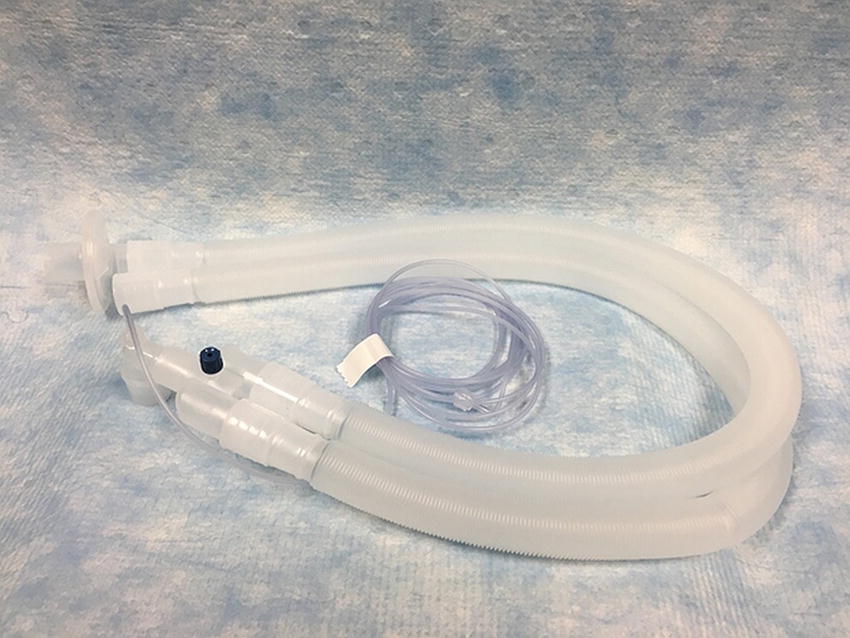
FIGURE 27.10. A modern dual limb circuit for a circle system. The space proximal to the patient from the blue cap is dead space. Also notice the bacterial/viral filter on the expiratory limb to protect the inside of the anesthesia machine from contamination.
The CO2 is absorbed in the canister. The fresh gas flow from the machine continues to fill the reservoir bag. When the reservoir is full, the relief valve opens and the excess gas is vented into the atmosphere or, better still, into a scavenging system. This circle system has the advantages of requiring only very low fresh gas flows (as low as 250-500 mL of oxygen to replace the oxygen used up by the body for metabolism), less consumption of anesthetic agents, reduction in atmospheric pollution, and conservation of heat and humidity. Disadvantages include a complex design with increased opportunity for malfunction, incorrect arrangement, slow changes in the inspired anesthetic concentration with low flows, increased resistance to breathing due to the CO2 canister and valves in the system, inhalation of soda lime dust, and potential generation of other compounds, possibly toxic, from reaction of the anesthetic agents with chemicals in the CO2 canister.
Carbon dioxide Absorption Systems
Circle absorber systems have been used extensively in North America for more than 70 years. As mentioned earlier, they were developed to reduce rebreathing of CO2, reduce the cost and use of expensive gases and inhalational anesthetic agents, as well as to reduce the amount of gas scavenging and ultimately the extent of environmental pollution. Two types of absorber are widely used: soda lime and Baralyme. Both react with CO2, and contain 80% calcium hydroxide and some potassium hydroxide.
In addition to 80% calcium hydroxide, soda lime contains water and sodium hydroxide (15% water, 4% sodium hydroxide, and 1% potassium hydroxide). Small amounts of silicate are also added to provide strength and prevent powdering as soda lime pellets are fragile.
Conversely, in addition to the 80% calcium hydroxide, Baralyme contains 20% barium hydroxide and may contain some potassium hydroxide. The addition of silica to Baralyme granules is not necessary to ensure hardness, and it is not necessary to add water, which is liberated by a direct reaction of barium hydroxide and CO2.
Newer CO2 absorbers (e.g., Amsorb, Litholyme) continue to come to the market. Some utilize calcium hydroxide with a compatible humectant (a hygroscopic substance with the affinity to form hydrogen bonds with molecules of water), namely, calcium chloride. Litholyme uses a lithium catalyst to promote color change. The absorbent mixtures do not contain strong bases such as sodium and potassium hydroxide, but do include two setting agents (calcium sulfate and polyvinylpyrrolidone) to improve hardness and porosity. New materials are designed to be effective absorbents of CO2 while being chemically nonreactive with sevoflurane, isoflurane, and desflurane.
The reaction of CO2 with absorbers at first seems to be complex, but the basic reactions are actually pretty straightforward and quite similar in the two systems. Soda lime (containing calcium hydroxide and sodium hydroxide) and Baralyme (containing calcium hydroxide and barium hydroxide) both involve reactions of CO2 and water to form carbonic acid, (CO2 + H2O → H2CO3), and both start with the same reactions. In each system, carbonic acid in the granules reacts with both calcium hydroxide and potassium hydroxide (present in each mixture) to form calcium carbonate, potassium carbonate, water, and heat. In addition, the carbonic acid also reacts very quickly with either the sodium hydroxide of soda lime or the barium hydroxide of Baralyme, to form the carbonate salt (sodium carbonate or barium carbonate), heat, and water. In the case of Baralyme, this concludes the reaction. For soda lime, the sodium carbonate then reacts with a calcium hydroxide mixture (as does the potassium bicarbonate) to form calcium carbonate as well as to reform the sodium hydroxide and potassium hydroxide found in the original mixture.
To be effective, the granules in the absorbing canisters must be properly configured to minimize resistance to airflow and to maximize the mixing of gases. To prevent rebreathing, the intergranular space should be greater than the patient’s tidal volume. Soda lime absorbs up to 26 L of CO2 per 100 g. Soft and crushable granules are converted to hard and noncrushable ones (calcium hydroxide changes to calcium carbonate-limestone), indicating exhausted soda lime. Different manufacturers add different indicator dyes to the absorber: some change from pink when fresh to white when exhausted; others change from white to purple. Correctly packed canisters allow flow and thus absorption throughout the canister, rather than channels of a columnar fashion that do not make effective contact with the particles. A larger cross-sectional diameter allows less turbulence, with reduced resistance and less dust. Baffles in the canisters reduce gas tracking down the walls, where spaces are relatively larger. There are several means to determine whether the particles within the canister are still effectively removing carbon dioxide, which are summarized below.
Methods to determine whether the absorbent is effective:
1. Capnography: Appearance of CO2 in the inspired gas is the best way to detect absorbent exhaustion.
2. Indicators: An indicator is an acid or base whose color depends on the pH, and the color change is indicative of absorbent exhaustion. Different manufacturers use different indicators, including phenolphthalein (white to pink), ethyl violet (white to purple), Clayton yellow (red to yellow), ethyl orange (orange to yellow), and mimosa Z (red to white). Color change may be misleading in certain circumstances, particularly those resulting in regeneration (peaking) after a rest period. Amsorb turns purple when desiccated, an additional advantage to prevent use of desiccated soda lime.
3. Temperature in the canister: Because CO2 neutralization is an exothermic reaction, changes in the absorbent temperature occur earlier than color changes. Studies have suggested that when the temperature of the downstream canister is higher than that of the upstream one, the absorbent should be changed in both canisters.
4. Clinical signs: Clinical signs of hypercapnia, such as tachycardia, hypertension, cardiac arrhythmias, and sweating, are usually late signs and are nonspecific.
It is important to note that the absorbents will interact with inhaled anesthetics to some extent. In some circumstances, interaction of sevoflurane with the strong bases present in soda lime or Baralyme results in the formation of a chemical called “Compound A,” which has been shown to cause nephrotoxicity in animals. These circumstances include (1) low total gas flow rate (below 1 L/min), (2) higher concentration of sevoflurane, (3) the use of Baralyme rather than soda lime, (4) higher absorbent temperatures, and (5) desiccated CO2 absorbent. Exposure of desflurane and isoflurane to soda lime and Baralyme can result in formation of carbon monoxide. Those factors include (1) higher anesthetic concentration, (2) higher temperature, (3) dry absorbent, (4) the use of Baralyme rather than soda lime, and (5) magnitude of CO production from greatest to least as follows: desflurane > enflurane > isoflurane > halothane = sevoflurane.
Summary
By understanding a few relatively simple principles, you should be able to understand and quickly become proficient with breathing apparatuses that you encounter. With such an understanding, you should be able to evaluate the advantages and disadvantages of any breathing system, and effectively troubleshoot problems.
Review Questions
1. What is the primary function of the anesthetic breathing circuit?
A) Ventilate the patient.
B) Deliver oxygen and anesthesia gases to the patient.
C) Protect anesthesia staff from exposure to anesthetic gases.
D) Remove all CO2 from the gas mixture by conducting gas to a CO2 absorber.
E) All of the above.
Answer: B
Breathing circuits are devices that provide the ability to deliver a defined gas or vapor to the patient. The other functions described are not performed by the breathing circuit or not performed by all designs of circuits. Ventilation of the patient is an active mechanical process performed by a mechanical ventilator (often part of the anesthesia machine) a dedicated ventilator, or a human being (either a spontaneously breathing patient, or the anesthesia provider squeezing a ventilation bag). Two additional functions of a breathing circuit are described, which are not performed perfectly by all designs of breathing circuits. The breathing circuit prevents release of anesthetic gas into the environment only in a closed (circle) system. The breathing circuit’s design must also permit the patient access to gas relatively free of CO2. A circle system performs this by carrying rebreathed gas to a CO2 absorber; open and semiopen circuits by supplying a fresh gas flow adequate to clear most expired gases into the environment, utilizing one-way valves, or both.
2. Which of the following could be considered an open breathing system?
A) Tarzan’s reed “snorkel”
B) A dual limb circle circuit system
C) Bain circuit
D) Open drop anesthesia mask
E) All of the above
Answer: D
Tarzan’s snorkel and the Bain circuit are examples of semiopen systems in that they use a tube to deliver gases to the patient. A circle system can be semiclosed or closed depending on the amount of rebreathing of exhaled gases. The only fully open system here is the open drop mask where the patient is breathing directly to and from the atmosphere.
3. Sevoflurane reacts with CO2 absorbent to create what dangerous chemical?
A) Compound A
B) Compound C
C) Carbon monoxide (CO)
D) Sodium hydroxide
E) None of the above
Answer: A
Compound A is created by the interaction of sevoflurane with a strong base present in the absorber material and has been shown to be toxic to the kidneys in animals. Carbon monoxide is produced by the interaction of isoflurane and desflurane and CO2 absorbents.
4. Which item is NOT an indication of exhausted CO2 absorbent?
A) Change in color of granules
B) Increase in temperature of absorber
C) Moisture in circuit
D) Increased inspired CO2
E) None of the above
Answer: C
Moisture is not an indicator of exhausted absorbent and is a natural by-product of the chemical reaction of most absorbents. All other indicators are regularly used to judge exhaustion.
5. Dead space is best described as
A) The volume of gas inspired and expired by the patient
B) The endotracheal tube
C) The inspiratory limb of the circuit
D) Any space where inhalation and exhalation coincide
E) All of the above
Answer: D
Any space where expired gas is not replaced by fresh gas can be considered dead space. When using a circle system, this can be any part of the circuit distal to the y-connection where the inspiratory and expiratory limbs come together.
6. To be an effective anesthesia breathing system, a device must have
A) A large reservoir
B) Low resistance
C) Low dead space
D) All of the above
E) None of the above
Answer: D
A large reservoir, low resistance to airflow, and low dead space are all key design features of an effective anesthesia circuit.
7. Rebreathing may be influenced by which of the following factors?
A) Dead space
B) The arrangement of the circuit assembly
C) Fresh gas flow
D) All of the above
E) None of the above
Answer: D
By increasing the size of the dead space, you increase the amount of rebreathed gas. By decreasing the fresh gas flow, the amount of expired gas washed from the circuit decreases and by changing the arrangement of the circuit, you can alter both these factors as demonstrated in Fig. 27.5.
8. What are some common components of CO2 absorbents?
A) Calcium hydroxide
B) Potassium hydroxide
C) Silica
D) Barium hydroxide
E) All of the above
Answer: E
Calcium hydroxide, potassium hydroxide, and silica are components of most modern CO2 absorbents. Barium hydroxide is the key component in Baralyme.
SUGGESTED READINGS
Dorsch JA, Dorsch SE. Understanding Anesthesia Equipment. 5th ed. Philadelphia, PA: Lippincott Williams & Wilkins; 2008.
Kain ML, Nunn JF. Fresh gas economics of the Magill circuit. Anesthesiology. 1968;29(5):964-974.
Roth P. Anesthesia delivery systems. In: Pardo MC, Miller RD, eds. Basics of Anesthesia. 7th ed. Philadelphia, PA: Elsevier; 2018:220-238.
Shankar Kodali B. Anesthesia breathing systems. Available from: http://www.capnography.com/. Accessed March 8, 2017.
Sword BC. The closed circle method of administration of gas anesthesia. Anesth Analg. 1930;9:198-202.