CHAPTER 41
Ultrasound
Introduction
Anesthesiologists are using ultrasound (US) for a variety of purposes. It is a powerful tool that is noninvasive, allows anesthesiologists to see structures beneath the skin, and does not produce harmful radiation. Compared to other types of imaging, US is relatively portable and inexpensive. In addition, US images are generated nearly instantly, providing real-time information at the bedside. Equipment may appear complex at first, but by understanding a few basic principles and becoming familiar with your US machine’s basic controls, you can quickly become comfortable using it.
US can be used to evaluate a patient (diagnostic) or as a visual aid in procedures (interventional). Diagnostic applications for the anesthesiologist are broad. They include examination of the heart (echocardiography) either externally (transthoracic) or by placing a special transducer in the patient’s esophagus (transesophageal echocardiography, covered in detail in Chapter 42); evaluation of a patient’s arteries or veins for narrowing or blockage, or to determine a patient’s volume status (do they have sufficient intravascular volume); examination of the internal organs; and evaluation for fluid collections in the patient’s skin, muscle, or body cavities. Procedural applications include assistance in vascular access, and performance of peripheral nerve blocks and spinal and epidural anesthesia. These specific applications of US are discussed in more detail in Chapter 16, Regional Anesthesia, and Chapter 36, Vascular Access.
This chapter focuses on the basic principles of US: the physics of US image formation, US imaging controls, basic US terminology, storage of US images, tips for optimizing conditions during US exams and procedures, and proper use and maintenance of US equipment. In order to illustrate the concepts we discuss, we have included pictures showing various US machine controls and sample US images. We made them using a variety of equipment available at our institution. This is not intended to be a comprehensive user’s manual for every US machine currently available. Different models of US machines have different types of controls and images of different quality; the concepts (of gain, depth, Doppler, etc.) are common to all machines. Some machines are far more complex than others. It is important to become familiar with the particular machine(s) you will be using in order to help the providers at your institution. However, each machine’s controls apply the same fundamental US concepts you will learn in this chapter.
Basic Ultrasound Physics/Machine Controls
The basic underlying principle of US physics is that sound waves are emitted and received by the US transducer. Sound waves are produced by a piezoelectric element in the transducer that vibrates when electrical current is applied. The sound waves emitted are reflected back to the transducer by the patient’s tissues. The transducer then measures the timing and strength of the reflected waves. Sound waves are emitted and received in a very thin beam, which is a flat plane about as thick as a piece of paper. The US machine then processes this information to produce the image on the US screen. The image produced is based on how fast the US waves move through various tissues of different densities and how much of the US energy the tissues reflect. US waves are above the range of normal human hearing (higher frequency) and so are not audible. The US transducer spends the majority of time receiving reflected US waves and is only emitting US energy about 0.1% (1/1,000th) of the time. There are no known harmful effects to live tissue from exposure to US waves in frequencies used clinically.
Frequency of Ultrasound Waves
The behavior of US waves is governed by the equation: λ = ν/ƒ. This describes the relationship between the frequency (ƒ) of US waves and their wavelength (λ). The velocity (ν) of US waves through tissue is relatively constant at approximately 1,600 m/s, though this varies slightly depending on the water content of the tissue. From this equation, you can see that frequency and wavelength are inversely proportional, meaning that as the frequency increases, the wavelength decreases. Conversely, as the frequency decreases, wavelength increases, or gets longer. US waves’ ability to travel through tissue and the resolution (sharpness) of the US image are dependent on frequency and wavelength (Fig. 41.1). The resolution of the US image is approximately two wavelengths. A shorter wavelength (higher frequency) produces a higher resolution US image.
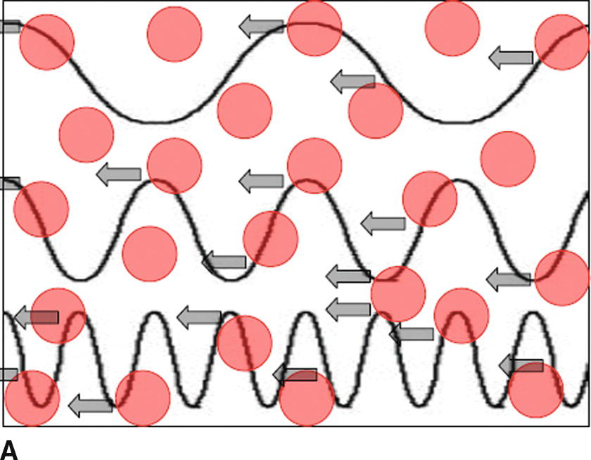
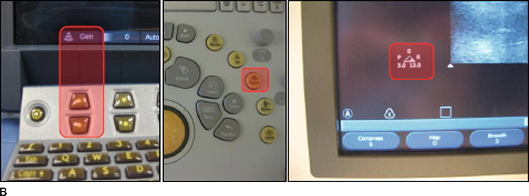
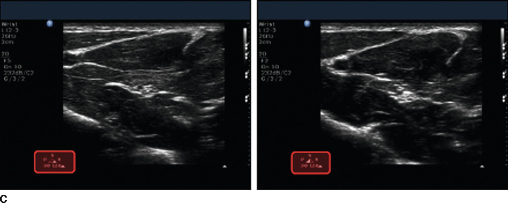
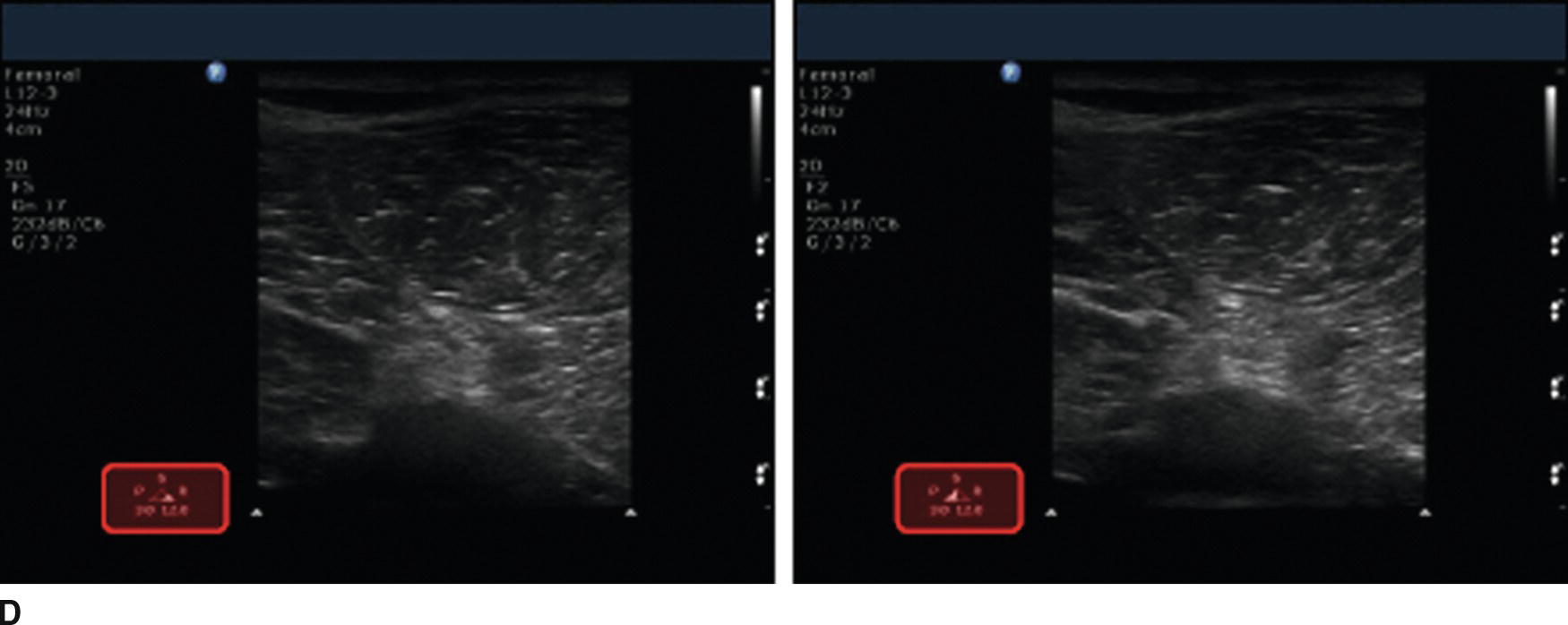
FIGURE 41.1. A: Schematic showing the relationship between frequency of US waves and tissue penetration. Red dots represent tissues/structures reflecting US waves (arrows). This shows that high-frequency waves are more likely to be reflected, preventing them from penetrating deeper. This is known as tissue attenuation. B: Controls for adjusting frequency on Sonosite (left) and Philips (middle, right) US machines. The Sonosite does not specify the actual frequency (in MHz) but uses a “Gen, Res, Pen” system. “Gen” is a midrange (general) frequency, “Pen” is a lower (penetrating) range, and “Res” is a high-frequency (resolution) range. The Philips machine also uses the “P,R,G” nomenclature on the US screen. C: US images of the same superficial area using high (left) and low (right) frequencies. The image on the left has better resolution. D: US images of the same deep area using high (left) and low (right) frequencies. The image on the right shows the nerve better though the resolution is lower.
The usual range of US waves emitted/received by US transducers commonly used by anesthesiologists is between 2-15 megahertz (MHz), or 2-15 million cycles per second. As previously mentioned, higher frequencies allow for better resolution, unfortunately, higher-frequency US waves do not penetrate tissue well and are not capable of imaging deeper structures (Fig. 41.1). So it may be helpful to use a lower frequency transducer to image deeper structures, but the image will not be as sharp (lower resolution).
Gain
The brightness of the US image can be adjusted using the gain controls on the US machine (Fig. 41.2). Gain is the amplitude of the US waves. Adjusting the overall gain control is similar to turning up the volume on a stereo. This makes the entire image brighter, but this may not improve the quality of the image, just as turning up the volume on a stereo may make the music louder but not improve the quality of the song. Fine gain controls such as the time-gain compensation (TGC) or lateral gain compensation (LGC) can be used to brighten or darken specific areas of the image (Fig. 41.2). This is similar adjusting equalizer setting on a stereo. To compensate for the effect of depth on signal strength, manual TGC sliders are often arranged in a diagonal pattern to increase the brightness lower (deeper) in the image. If adjusting TGC and LGC controls, they should be checked to prevent overadjusting the image as this can produce significant artifacts and make US image interpretation more challenging. When in doubt, it is probably best to leave the sliders in a neutral position. Slight adjustments can then be made to “fine-tune” the US image as necessary. Modern US machines may instead autoadjust gain to optimize the image (Fig. 41.2D).
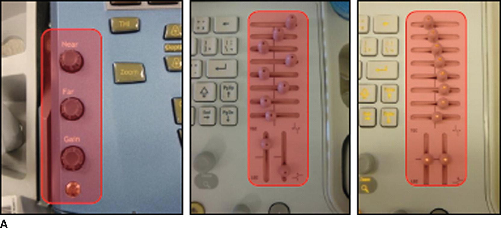
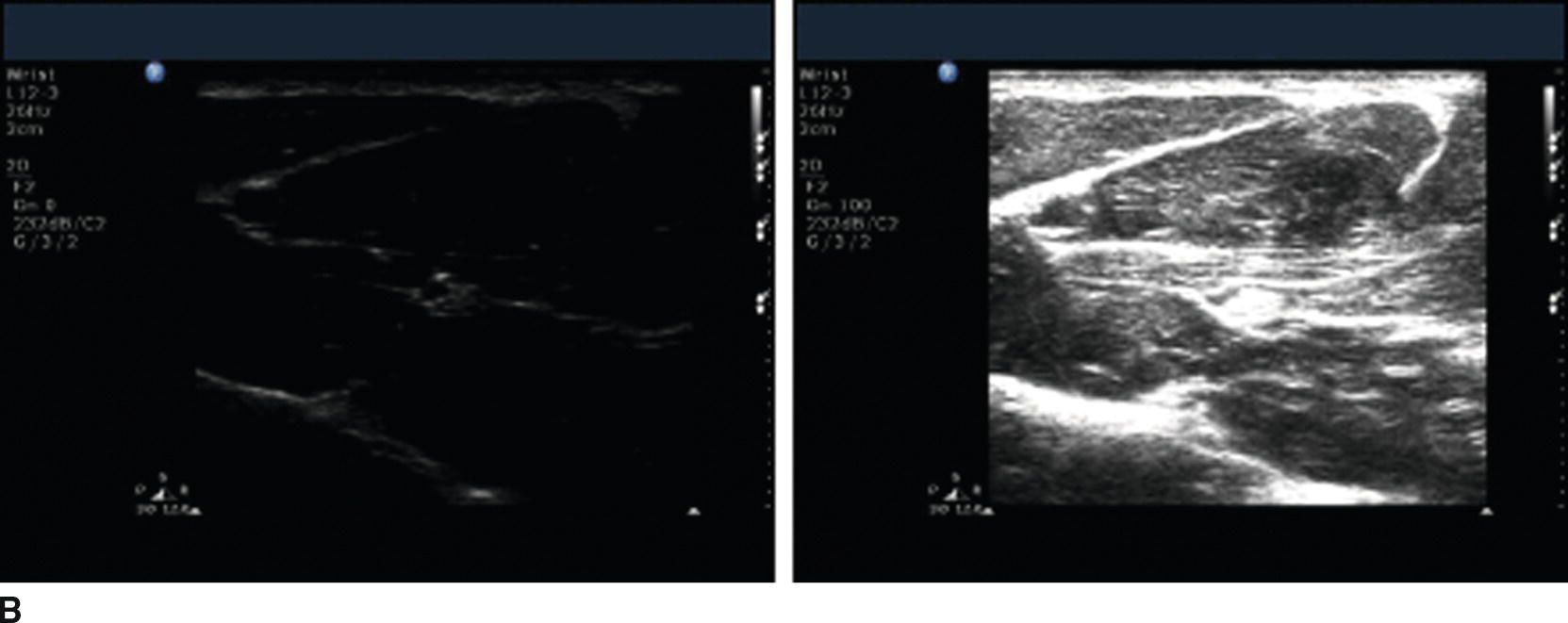
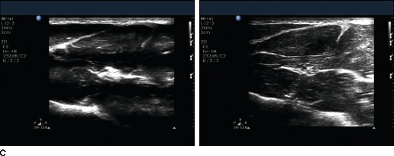
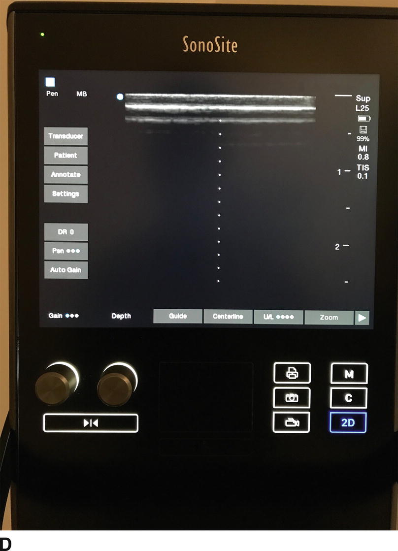
FIGURE 41.2. A: Pictures of gain controls for Sonosite (left) and Philips (middle, right) US machines. The Sonosite allows adjustment of overall gain and separate adjustment of gain in the near and far areas of the US image. The Philips unit allows for adjustment of overall gain as well as at different levels of the US image (time-gain compensation or TGC, top sliders, move side to side) as well as on the edges of the US image (lateral gain compensation or LGC, lower sliders, move up or down). The TGC and LGC sliders are arranged haphazardly in the middle, and more conventionally in the image on the right. B: Same US image with gain adjusted. On the left, the gain is too low, making the image dark and hard to interpret. On the right, the gain is too high, making the image too bright and again hard to interpret. C: Same US image with TGC and LGC adjusted. The image on the left shows how improper use of the TGC controls can give the US image a “striped” appearance, making interpretation difficult. The image on the right shows how improper adjustment of the LGC controls can make one side of the US image too bright or too dark, again making interpretation difficult. D: Same controls in next-generation US machine using soft keys and autogain control. This particular machine has dedicated knobs for gain and depth, and, on this particular screen, a soft key for “autogain” replacing the TGC and LGC sliders.
Depth
The depth of the US image can be adjusted on virtually every US machine (Fig. 41.3). It is important to adjust the depth appropriately so that the structure(s) of interest is on the screen. Too much depth will narrow the image, make target structures smaller on the US image, and include deeper structures that may not be relevant to procedure being performed. In general, it is usually ideal to have the entire target structure(s) in the US image and adjust the depth so that the target(s) is centered in the image. This allows the anesthesiologist to see other structures in the area that he or she may wish to avoid puncturing unintentionally, and help visualize the needle if it is directed deeper than intended (Fig. 41.3).
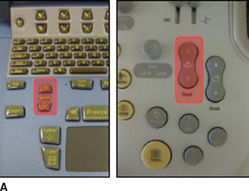
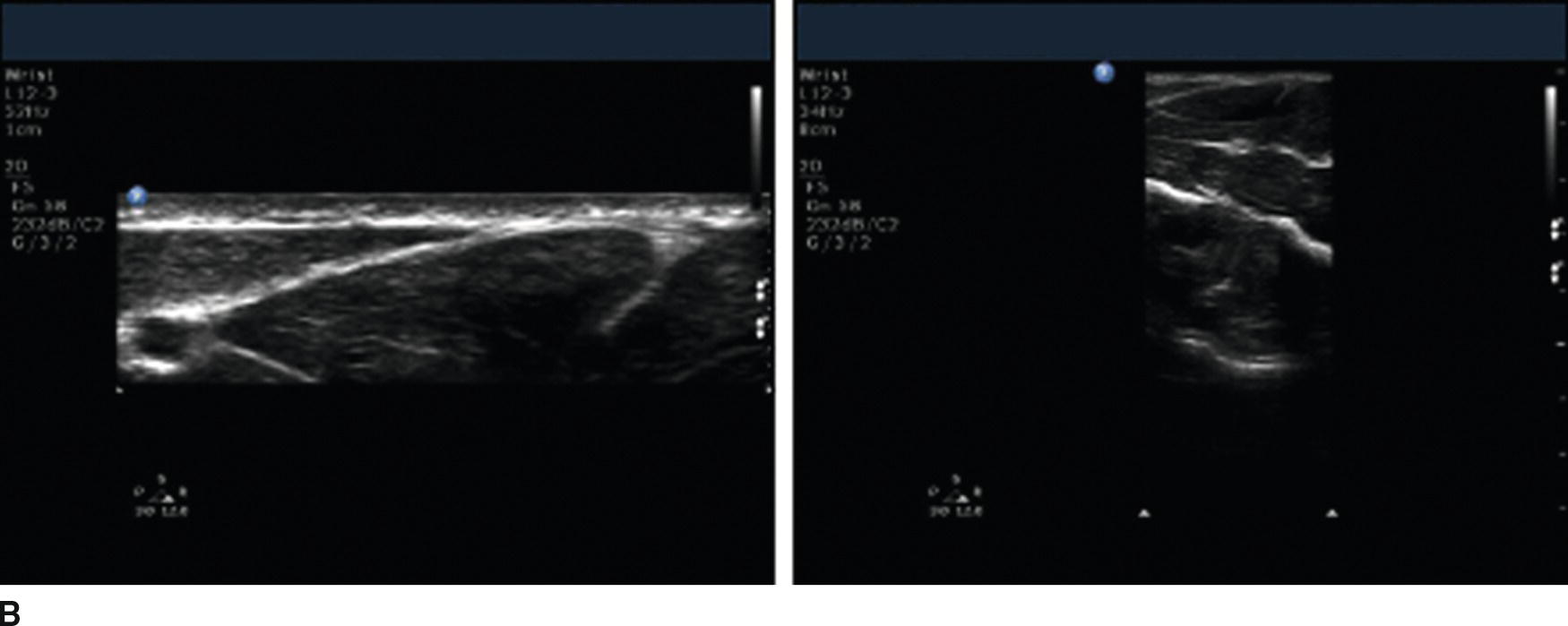
FIGURE 41.3. A: Depth controls for the Sonosite (left) and Philips (right) US machines. B: US images of the median nerve showing too little (left) and too much (right) depth. The nerve is not seen in the image on the left as the field of view is too shallow. The nerve appears very small in the image on the right as the field of view is too deep.
Doppler/Color
Another useful feature of most US machines commonly used by anesthesiologists is known as Doppler (or color) imaging. This uses a physical phenomenon known as the Doppler shift to measure movement. Doppler shift describes the effect of an object’s direction and velocity on the sound emitted by the object as detected by the receiver. For example, as a train moves toward you, the sounds it makes have a higher pitch, while the sounds it makes have a lower pitch as it moves away from you. The faster the object is moving, the greater the change in pitch. The US transducer acts as the receiver. Objects moving toward the transducer reflect US waves at a higher pitch than emitted and those moving away at a lower pitch than emitted (Fig. 41.4). This phenomenon can be used to measure flow through blood vessels.

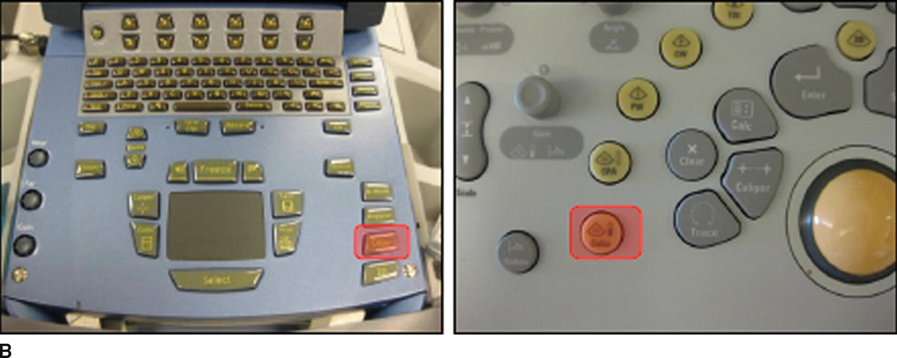
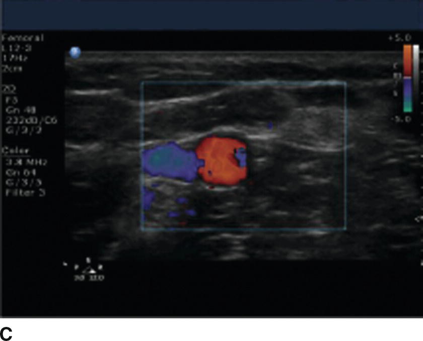
FIGURE 41.4. A: Schematic showing the effect of movement of an object on the frequency of sound waves emitted or reflected by an object. The object (dot) is moving in the direction of the arrow (left) effectively compressing the sound waves moving in the same direction as the object (higher frequency) and dilating the sound waves moving in the opposite direction (lower frequency). This is known as the Doppler effect. B: Color imaging controls for the Sonosite (left) and Philips (right) US machines. C: Still image showing use of color imaging. The color denotes flow through blood vessels. In this image, the vein is blue and the artery is orange/red. This is due to the color scale seen in the upper right area of the US image. Veins may not always appear blue and arteries may not always appear orange/red depending on the color scale selected and the orientation of the US transducer relative to the vessels in the US image.
The Doppler effect is displayed on the US screen as color, and the color scale can be used to show how fast blood (or any other substance) is moving toward or away from the US transducer. If the direction of flow is perpendicular to the transducer, flow is neither toward nor away from the US transducer, and there may not be color on the US screen even though there is blood flowing through the vessels. Tilting the US transducer (discussed later) toward or away from the direction of flow may improve the color signal.
Focus
US waves emitted from the transducer are shaped like an hourglass (Fig. 41.5). The narrowest portion of the beam is known as the “focal zone.” In this area, there is the least interference among US waves and the US image is clearest. In general, the focus depth should be adjusted so that it is centered over the target structure(s). If multiple US beams are being used simultaneously (see below), the number of focal zones can be adjusted as well. If multiple beams are used, the focal zone can be made wider or narrower to include more or less of the US image.
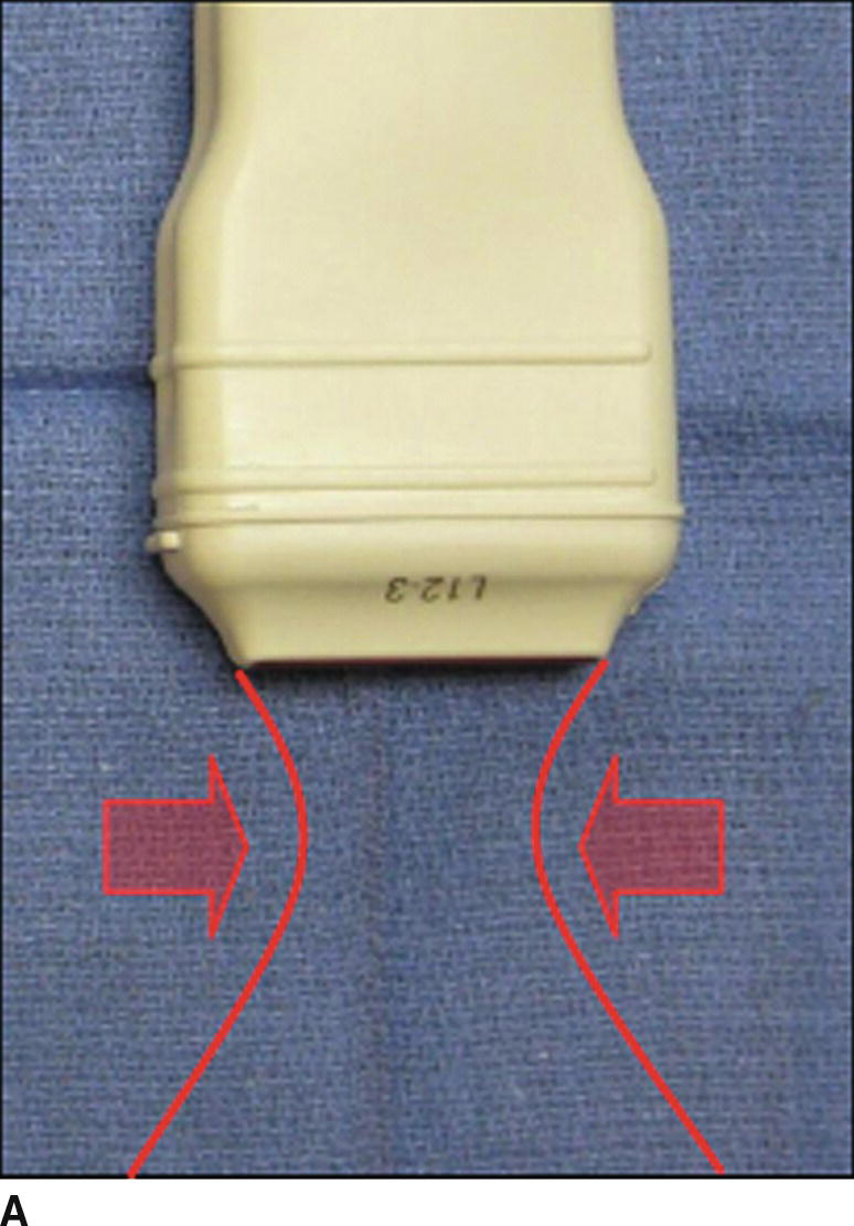
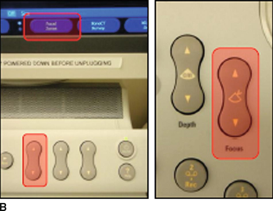
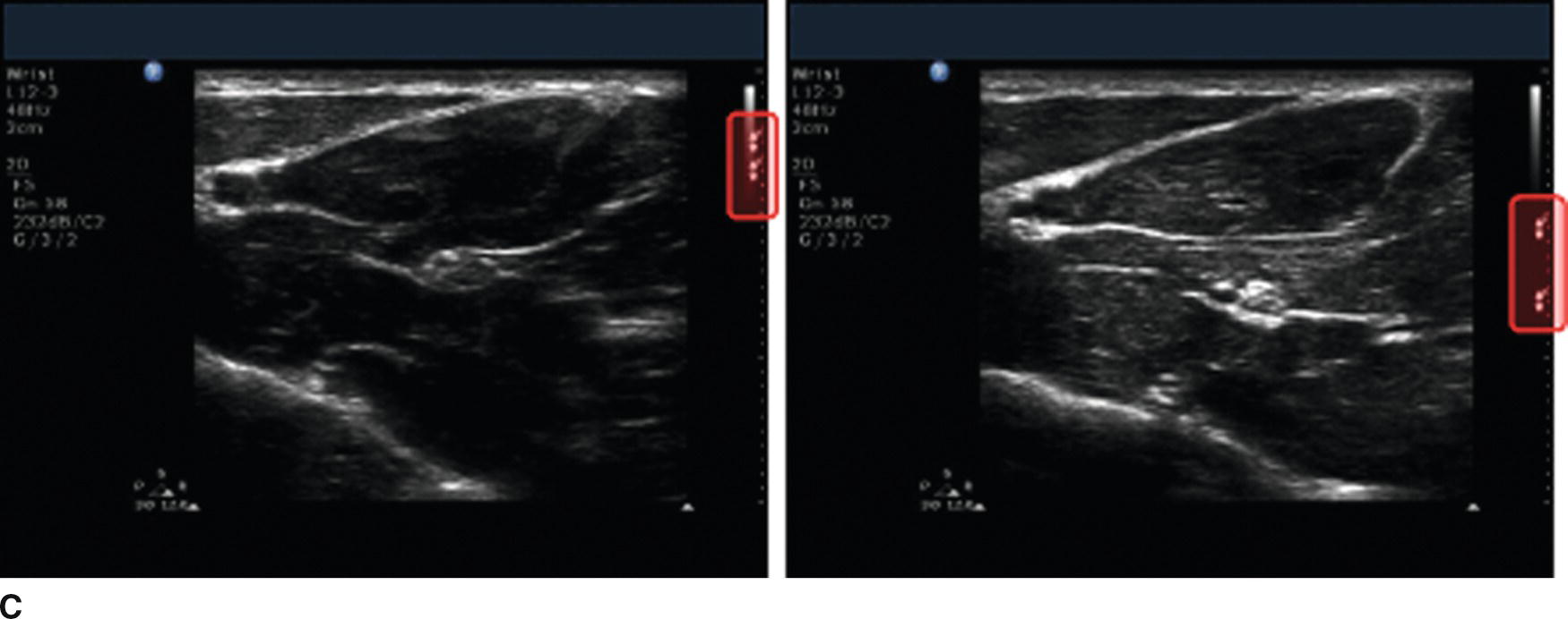
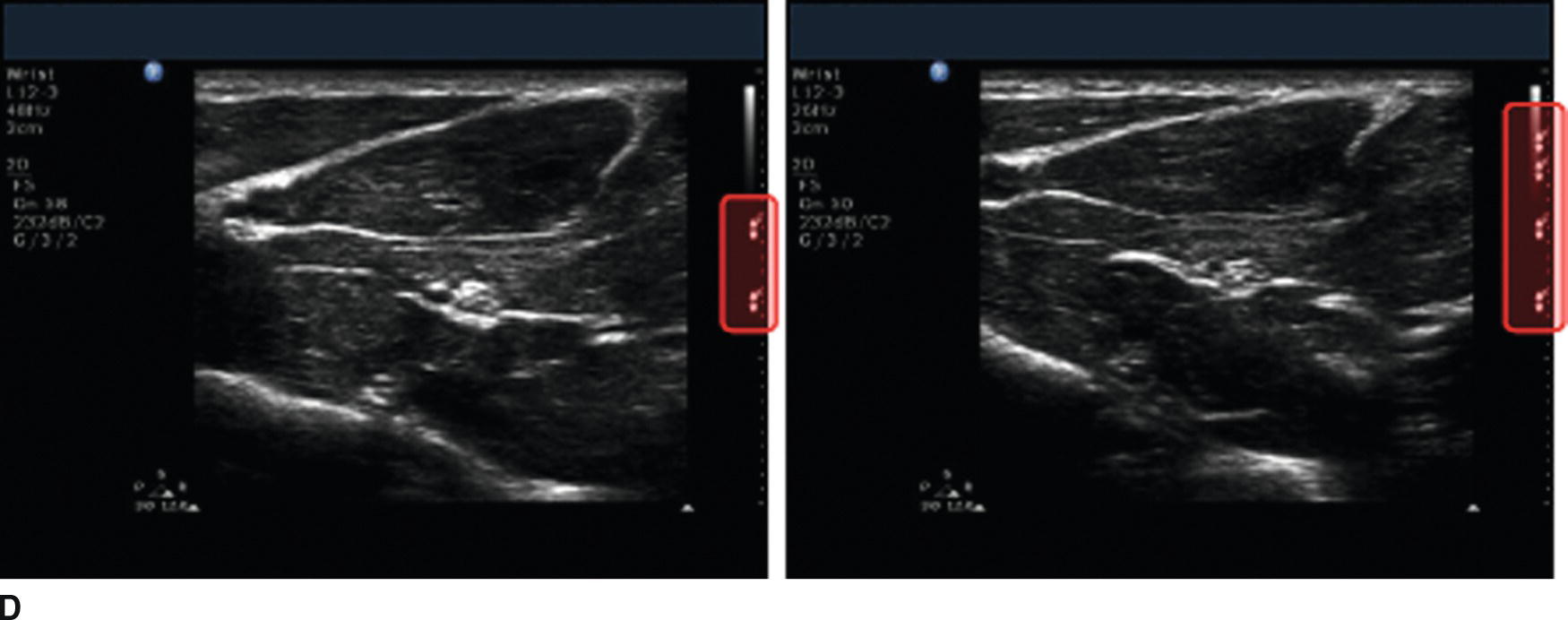
FIGURE 41.5. A: The US beam has an “hourglass” shape that is focused where the beam is narrowest (the focal zone). The distance from the transducer at which the beam is focused (focal depth) as well as the number of beams that can be focused (number of focal zones) can be adjusted. If multiple focal zones are used, these can be tightly or widely spaced depending on the size of the area of interest. B: Focal zone controls for the Philips US machine. The focus depth controls are shown on the left, and the number of focal zones control is shown on the right. C: Identical US images showing inappropriate (left) and appropriate focus depth (right). The nerve in the image on the right appears clearer. D: Identical US images using two (left) and four (right) focal zones. The number of focal zones is displayed on the right side of the US image (highlighted).
Multibeam
Many US transducers currently in use are now capable of emitting multiple US beams simultaneously (Fig. 41.6). These may be oriented in slightly different directions or use frequencies that are slightly different (harmonic imaging). This may reduce artifacts in the US image and may give the US image a “smoother” appearance. This also requires more processing of the image, so the frame acquisition rate (number of times per second the US image is changed) may decrease. Movement within the image appears choppy. Multibeam imaging can usually be turned on or off easily, and there is usually a marker (varies by manufacturer) on the image to show if this feature is being used or not.
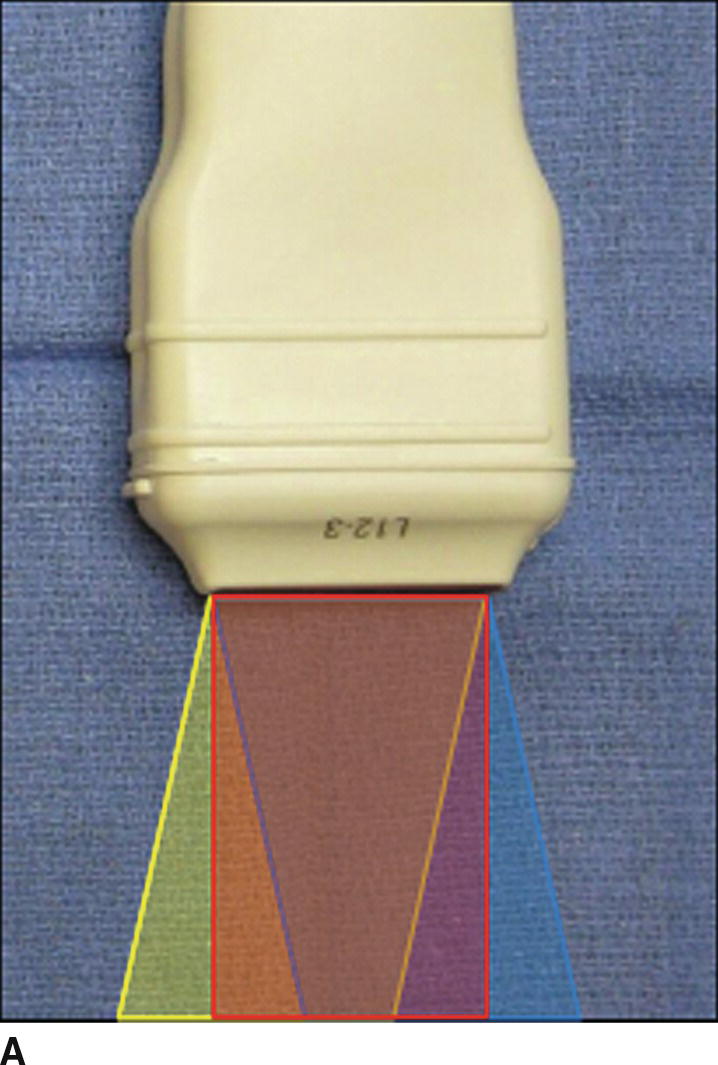
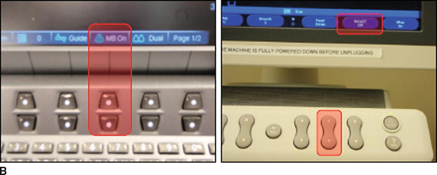
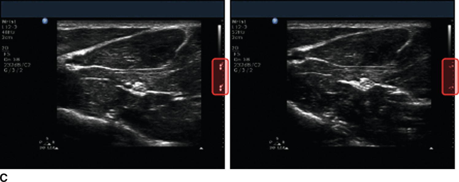
FIGURE 41.6. A: Schematic of multibeam imaging. The different colored areas below the US transducer represent distinct US beams, each oriented a slightly different direction. The US transducer receives reflections from each beam, and the machine combines the signals to reduce artifact and produce a “smoother” US image. Some anesthesiologists prefer not to use multibeam imaging, however. B: Multibeam controls for the Sonosite (left) and Philips (right) US machines. C: Identical US images with multibeam imaging turned on (left) and off (right). The appearance of the focus depth indicators (highlighted) is different if multibeam imaging is off or on.
Compression
Some US machines may allow for adjusting the compression or gray scale of the US image. A narrower gray scale (more compression) will make the image appear more homogeneous, while decreasing the compression (wider gray scale) will provide more contrast. Some types of US machines have different scales that can be selected from a menu, or filters that color the image differently (e.g., sepia or violet tone).
Presets
Many US machines come equipped with “preset” combinations of the above settings to optimize the US image for specific types of procedures (Fig. 41.7). These have been created by the manufacturers to optimize imaging for specific types of exams or procedures without having to manually adjust all of the machine’s settings. Depending on patient-specific factors (such as size), the preset may or may not actually provide optimal settings. Often, the preset is a good way to start imaging, and fine adjustments (depth, frequency, gain, focus, etc.) can then be made to improve the image quality.
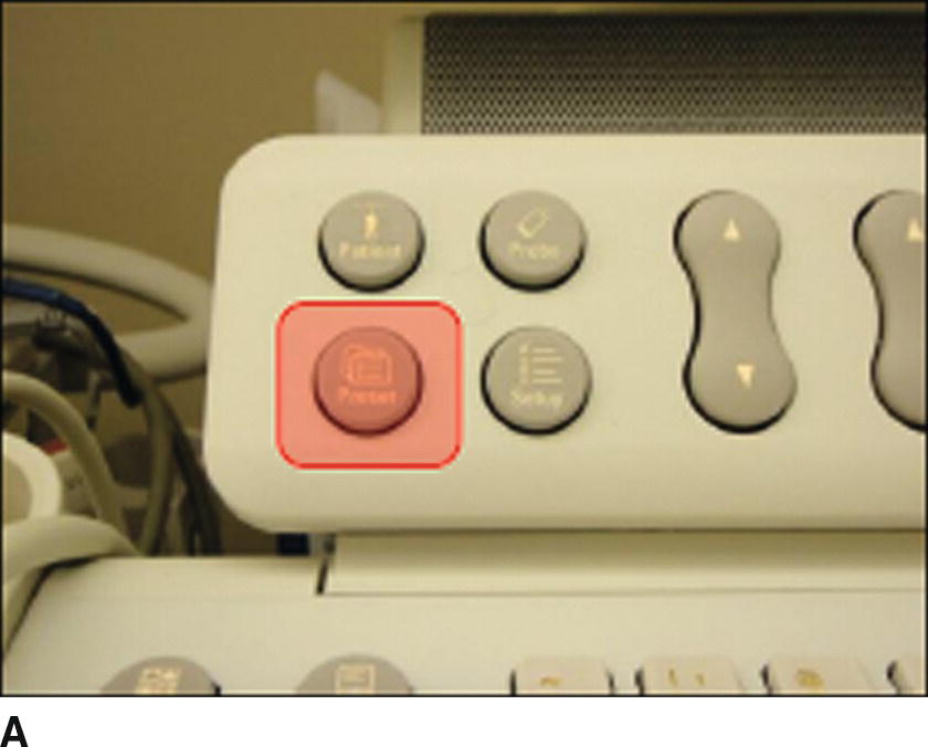
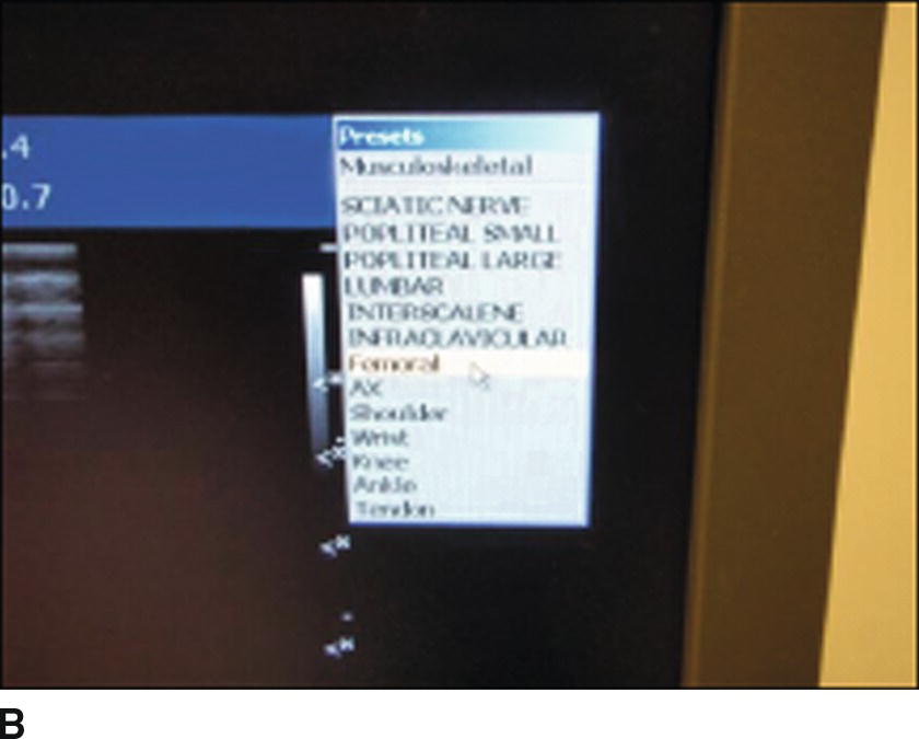
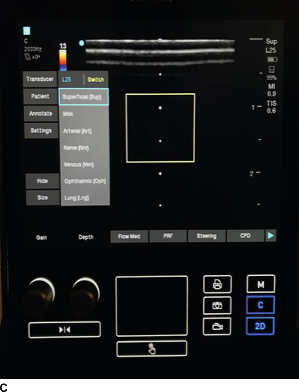
FIGURE 41.7. A: Presets button on the Philips US machine (highlighted). B: Screenshot showing presets menu on the Philips US machine. The appropriate preset can be selected for the procedure being performed. C: A different machine using soft key controls with similar presets. This particular machine uses dedicated knobs for gain and depth, with, on this screen, soft keys controlling presets for standard applications.
Types of Transducers
Different types of US transducers (probes) may be helpful for specific procedures (Fig. 41.8). Most US machines can be used with a variety of transducers. These may all be attached to the US machine at the same time or may need to be attached separately at the desired time of usage. If multiple transducers are connected to the US machine, the transducer can be selected from a menu using a control on the machine. If only one transducer can be attached at a time, the transducer that is attached will be the one that is able to be used for scanning. The interface between transducers and machines varies by manufacturer (Fig. 41.8). In general, manually changing transducers does not require any special tools and can be done in seconds.
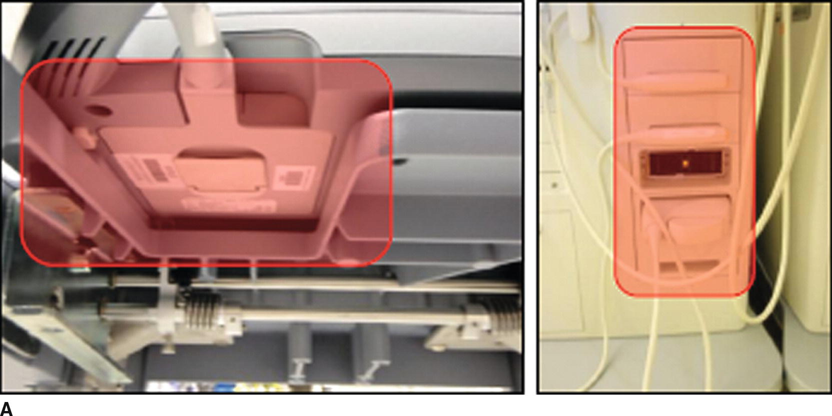
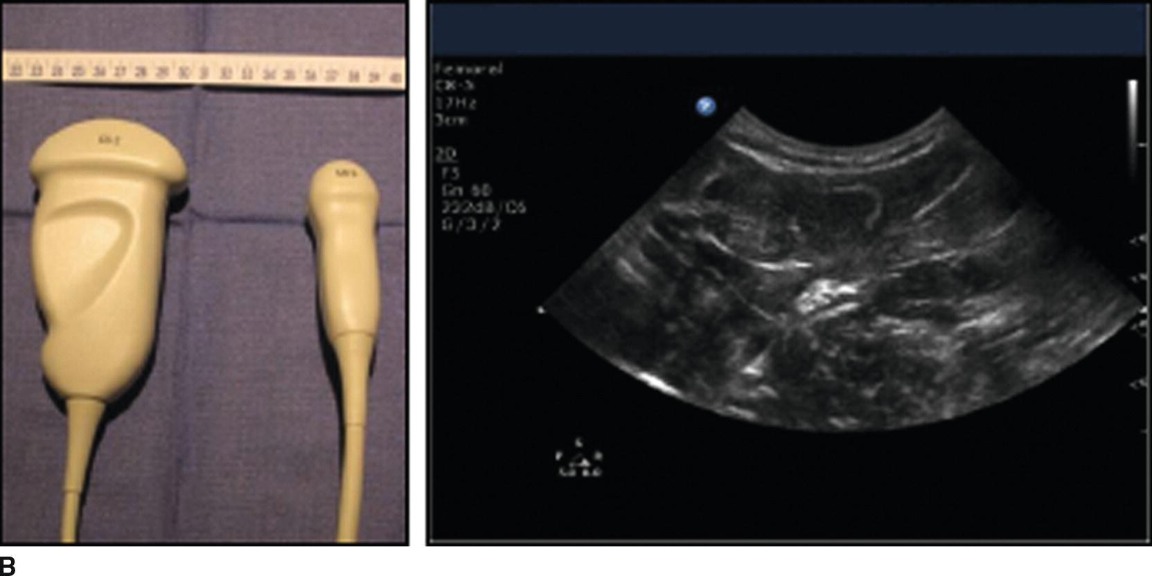
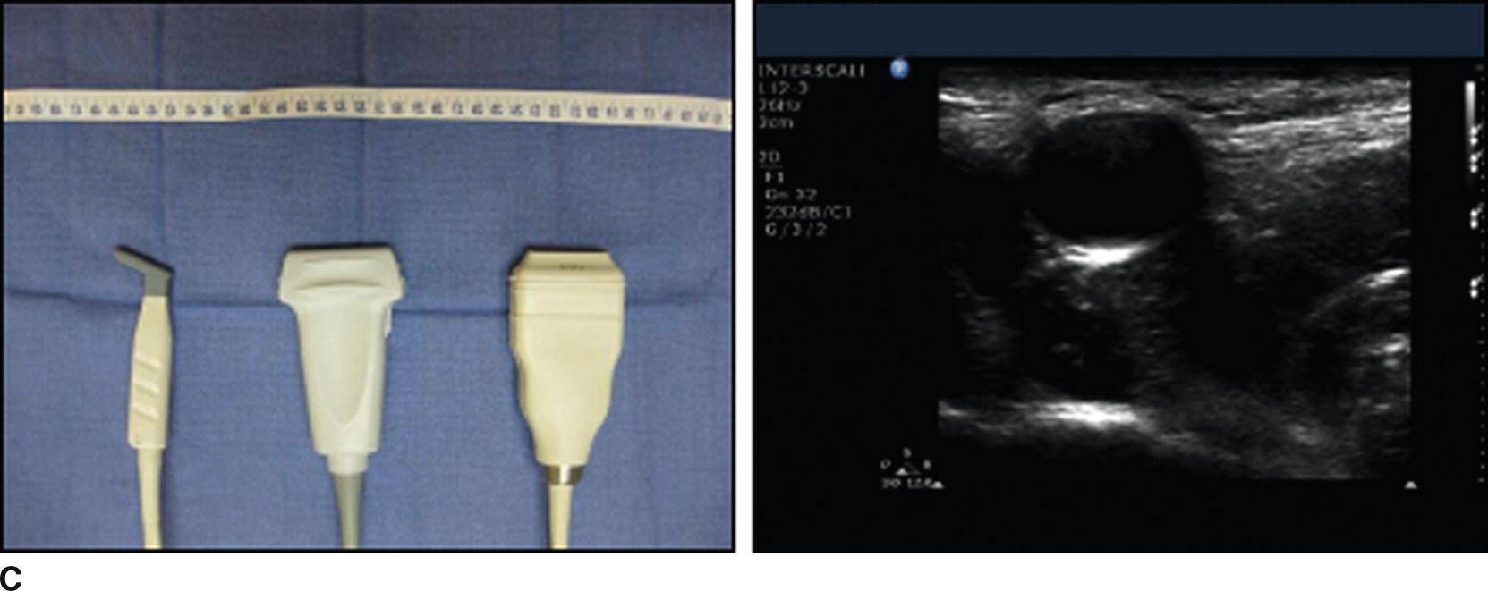
FIGURE 41.8. A: Attachments for different transducers on the Sonosite (left) and Philips (right) US machines (both highlighted). B: Curved array US transducers (left) and an US image obtained using a curved array transducer (right). C: Linear array US transducers (left) and an US image obtained using a linear array US transducer (right). Both the curved and linear array transducers come in a variety of widths (see rulers in images). This is referred to as the “footprint.”
In general, US transducers can be divided into two main categories: linear array and curved array. Linear array transducers emit and receive US waves directed perpendicular to the surface of the transducer (Fig. 41.8). This produces a square- or rectangular-shaped image on the US screen. Linear array transducers are the most commonly used by anesthesiologists. They do not distort the image and allow for straightforward needle guidance during procedures. Curved array transducers emit and receive US waves directed radially from the surface of the transducer. This produces a wedge-shaped or semicircular image on the US screen. Curved array transducers may provide a wider field of view, which can be helpful in many circumstances. In addition, the curved array transducer can be “rocked” from one side to the other to further widen the field of view. Due to distortion of the US image (especially near the edges), it may be more difficult to determine the correct angle for needle insertion or advancement. Often the needle needs to be oriented more steeply than anticipated.
Each transducer emits and receives US waves within a range of frequencies. Some transducers use low frequencies and are best suited for deeper exams and procedures. Others use higher frequencies and are best suited for more superficial procedures. The range of frequencies emitted and received by the transducer is usually written on the transducer and/or is displayed on the US screen.
Another feature of transducers relevant to their use by anesthesiologists is the size of the surface of the transducer that comes into contact with the patient. This is referred to as the transducer’s “footprint.” Wider transducers may provide a wider field of view, but may be difficult to position in tight spaces such as between ribs, or in small spaces such as the area above the clavicle of a child.
Most anesthesiologists will be able to do the majority of exams or procedures with a single transducer. Transducers are expensive, and costs range from $3,000 to more than $10,000. Most practices will not use many transducers unless they use US very frequently. However, as more anesthesiologists use US and the applications for use of US continue to grow, more practices are likely to purchase and use a variety of transducers.
Ultrasound Terminology
Knowing the terminology used by anesthesiologists can help you communicate during US exams or procedures. Key terminology relates to the way structures are imaged, ways in which the US transducer can be moved during exams and procedures, and the orientation of needles relative to the US transducer during interventional procedures, and terms used to describe the appearance of tissues or structures on the US image.
Structures are usually imaged using a “short axis” or “long axis” view (Fig. 41.9). The short axis view generally refers to a cross-sectional image. Advantages of the short axis view are that it is often easier to recognize structures as well as the arrangement of adjacent structures in this view. In addition, the probe can be moved longitudinally along the patient’s skin to “follow” structures proximally or distally. This can help confirm the identity of a structure or plan a safe needle trajectory at the location where the target is close to a large blood vessel or other vital structure.
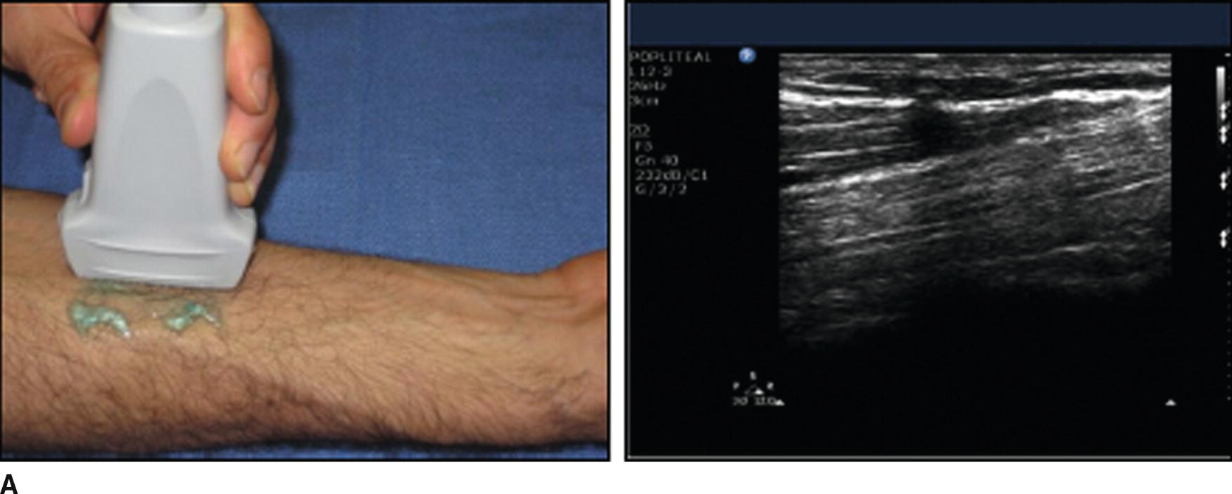
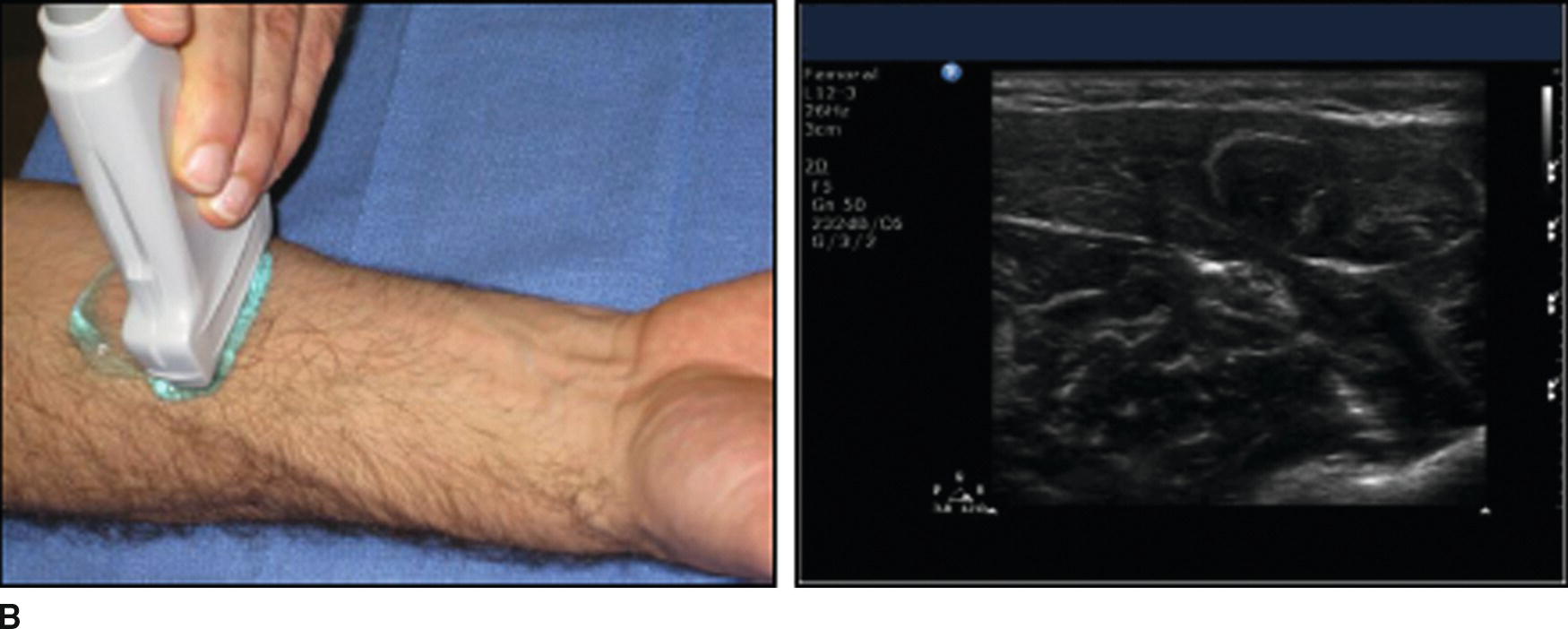
FIGURE 41.9. A: Long axis imaging of the median nerve in the forearm. The US transducer is oriented parallel to the nerve (left), producing an image of a section of the nerve that appears as a “stripe” on the US screen (right). B: Short axis imaging of the median nerve in the forearm. The US transducer is oriented perpendicular to the nerve (left), producing a cross-sectional image of the nerve (right).
The long axis view involves rotating the transducer 90 degrees (see below) relative to its orientation during short axis imaging to allow for imaging of a long section of a structure (Fig. 41.9). This may be especially useful for looking at blood vessels, as abnormalities (such as clots) may not be well visualized using the short axis view. It may be difficult to keep structures in view, however, as slight tilting of the transducer (see below) may move the plane of the US beam so much that the structure of interest may no longer lie in the plane and no longer appear on the US image.
The US transducer can be moved relative to the patient to optimize the US image. The basic moves that can be made are easily remembered using the “PART” mnemonic. The “P” refers to the amount of pressure used to make contact between the transducer and patient (Fig. 41.10). Too little pressure can result in poor contact and lead to “shadowing” on the US image. This is an artifact caused by the inability of US waves to travel through air. Too much pressure may be uncomfortable for the patient and can compress fluid-filled structures such as blood vessels (especially veins, which have thinner walls than arteries).
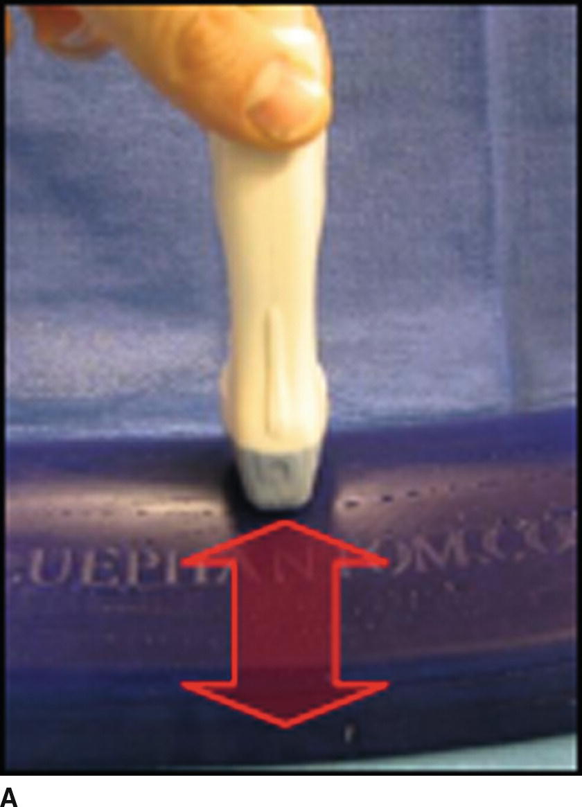
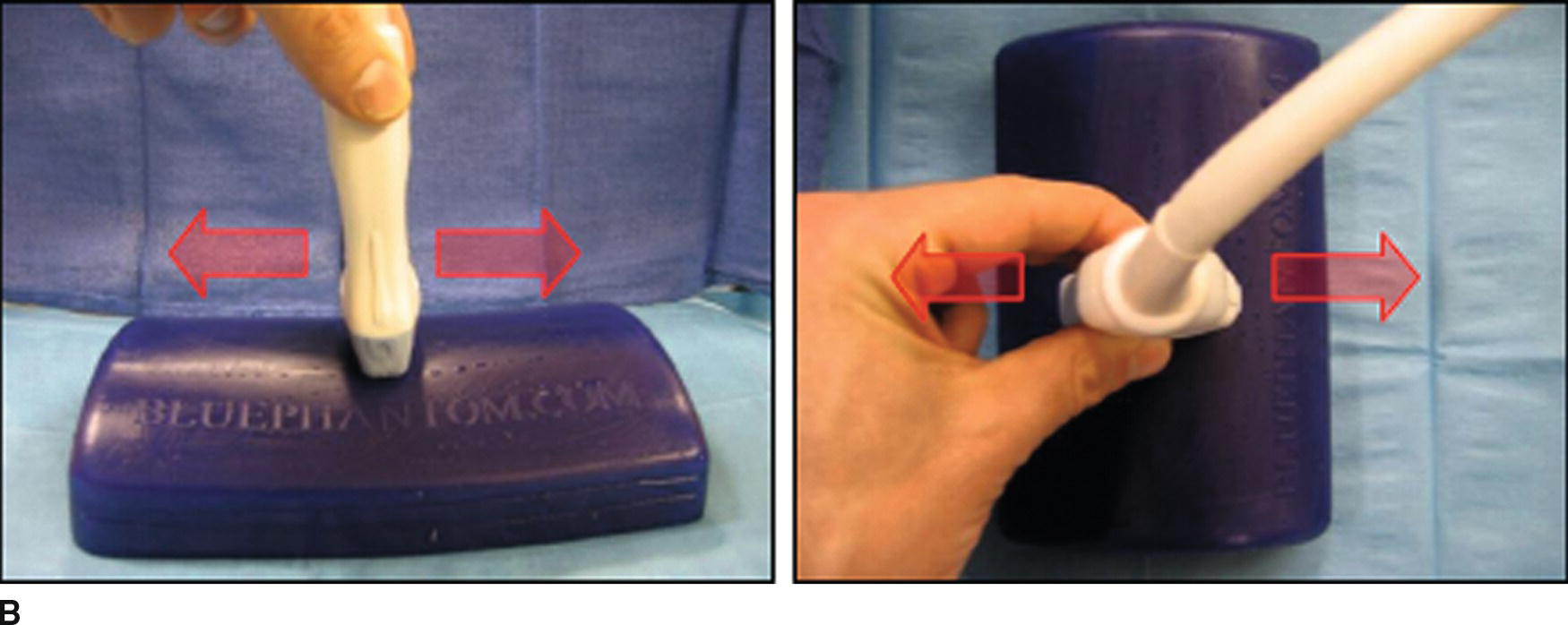
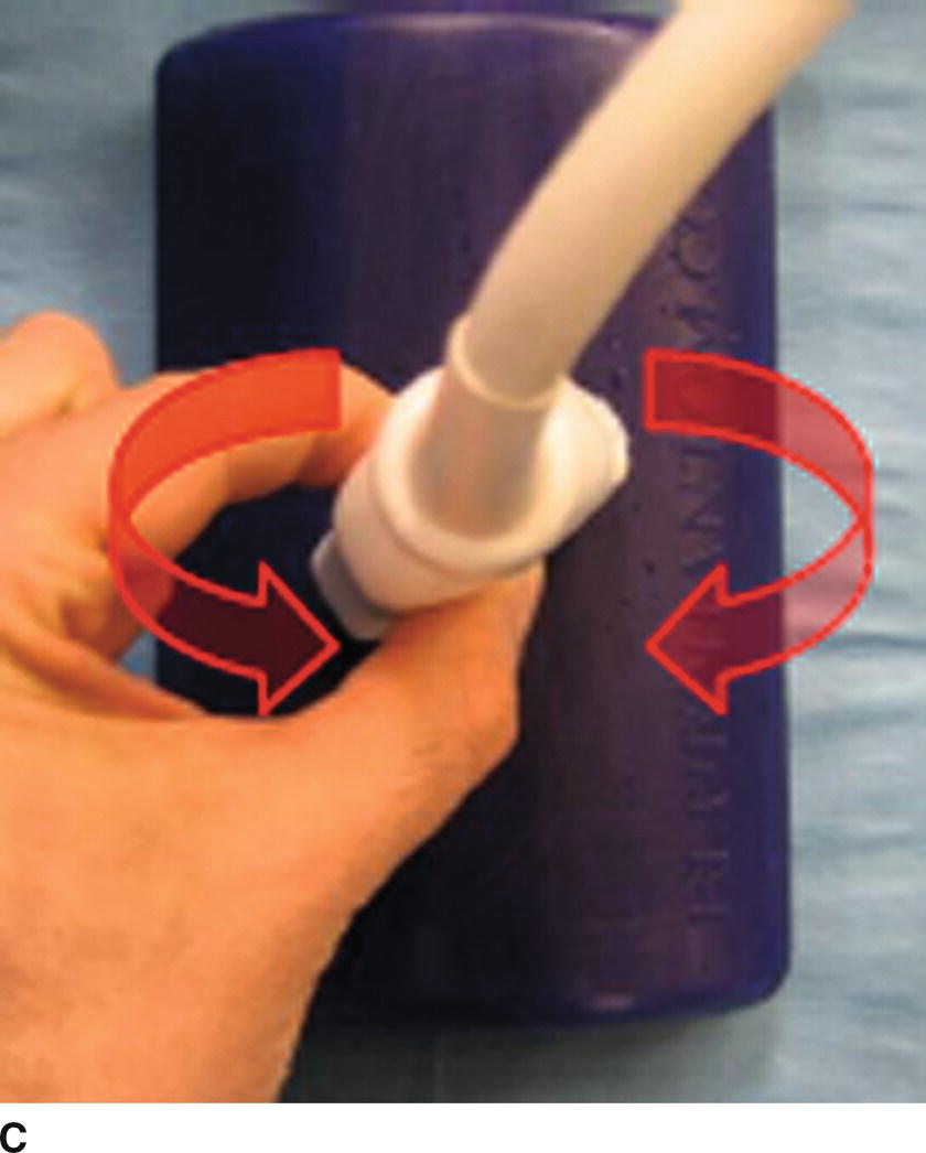
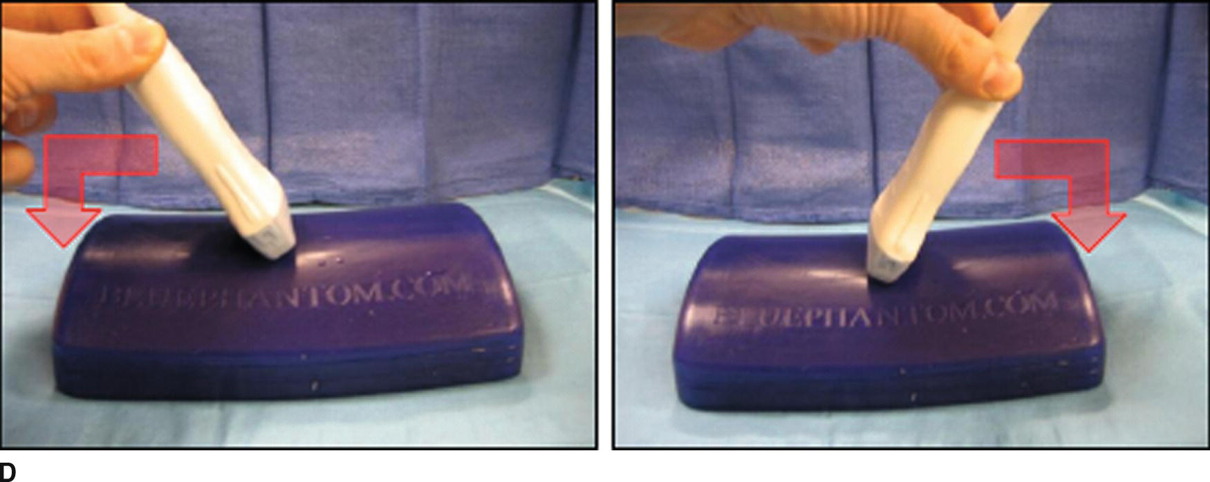
FIGURE 41.10. The “PART” maneuvers. A: The amount of pressure applied to the US transducer can be adjusted. B: The alignment of the US transducer can be adjusted laterally or longitudinally. C: The transducer can be rotated. D: The transducer can be tilted to either side.
The “A” refers to the alignment of the transducer relative to the target structure(s) (Fig. 41.10). The transducer can be moved from side to side and along the patient to fully evaluate the anatomy of the area(s) of interest and to place target(s) in an optimal position within the image on the screen of the US machine.
The “R” refers to the rotation of the transducer relative to the target structure(s) (Fig. 41.10). Anatomic structures may be easiest to recognize in cross section, so the transducer may need to be rotated relative to the patient’s surface in order to identify them. Once structures are identified, rotating the transducer 90 degrees will allow for evaluation of the structures using the long axis view, which may provide additional information. Also, once the structure(s) of interest has been identified, the transducer can be rotated to produce an “oblique” image if this allows for a more advantageous needle trajectory during procedures.
The “T” refers to tilting the transducer relative to the surface of the patient (Fig. 41.10). Again, as anatomic structures are often most easily recognized in cross section, the transducer may need to be tilted if the structure is not parallel to the patient’s surface (moving deep to superficial or superficial to deep). Often structures can appear or vanish from the US image depending on the way in which the transducer is tilted.
Additional important terminology relates to the orientation of the needle relative to the US transducer during interventional procedures (Fig. 41.11). The “in-plane” technique involves inserting the needle in the center of the short side of the transducer and advancing the needle so that its tip and, ideally, its entire shaft can be visualized within the plane of the US beam. The “out-of-plane” technique involves inserting the needle along the long edge of the US transducer so that it is oriented perpendicularly to the plane of the US beam. Each technique has advantages and disadvantages, and some anesthesiologists may prefer one technique over the other for specific procedures. In general, the in-plane technique is the most commonly used during nerve block procedures, and the out-of-plane technique is most commonly used during vascular access procedures.
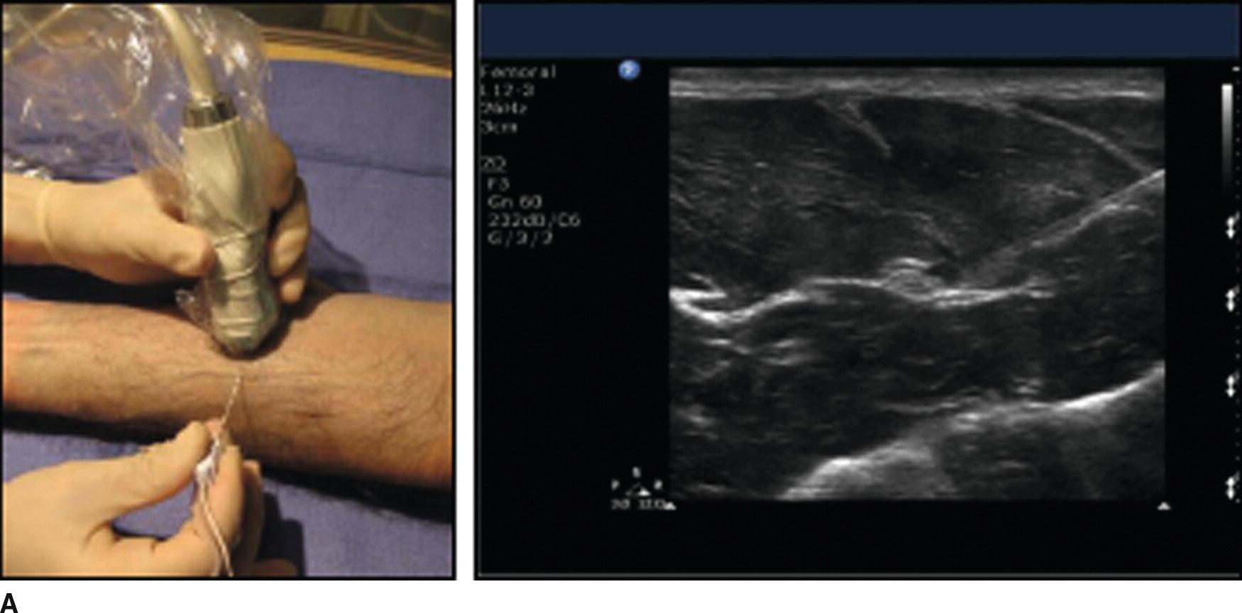
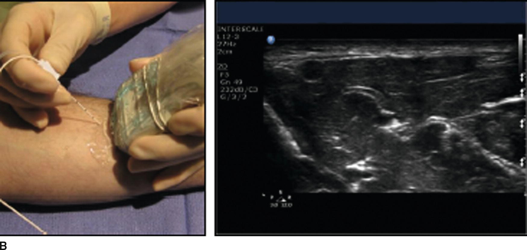
FIGURE 41.11. A: In-plane needle technique. The needle is inserted along the lateral edge of the transducer and directed parallel to the long axis of the transducer in order to place the needle's shaft in the plane of the US beam (left). A US image showing the shaft of the needle approaching a nerve (right). The needle appears as a white stripe coming from the upper right portion of the screen toward the nerve in the center of the image. B: Out-of-plane needle technique. The needle is inserted along the long edge of the US transducer and directed perpendicular to the long axis of the transducer (left). This may not show the needle well as only a cross section of the needle will be in the plane of the US beam. An US image of the out-of-plane technique (right) shows only a shadow where the needle's shaft crosses the US beam, just to the right of the nerve in the center of the US image.
There are several specific terms used to describe the appearance of tissues or structures in US imaging. Echogenicity of a tissue or structure refers to how strongly it reflects US waves. Hyperechoic structures reflect a large percentage of US waves that contact them, and as such they appear bright on the US screen. Conversely, structures that do not strongly reflect US waves appear dark on the US image and are described as hypoechoic. Different tissues or structures can be recognized as different parts may be hyper- or hypoechoic. For example, bones have a hyperechoic surface on the US screen but are hypoechoic below the surface because US waves bounce off the dense surface and fail to penetrate deeper. This produces a dropout in signal, also known as acoustic shadowing. It resembles a shadow formed as an object blocks light.
Another important property of tissues and structures relevant to US is their compressibility. Fluid-filled structures are usually compressible, while solid structures usually are not. This can be helpful to distinguish nerves from blood vessels or muscles from fluid collections. Structures can be simply described as “compressible” or “not compressible.”
Storage of Ultrasound Images
Most machines have the capability of saving or printing an image; you should know the steps for doing so on your US machine. An image is usually required for both documentation and billing of an US-guided procedure. A provider may be focused on the procedure at hand and forget to ask for an image to be printed; it is often helpful for you to ask if a printed image is needed. For central line placement, this image is typically an image of the guidewire or actual line in the vessel. For peripheral nerve blocks, this image is typically a picture of the needle tip near the nerve or with local anesthetic surrounding the nerve of interest.
Most modern machines are equipped with video recording capability. This is helpful for teaching and learning from the procedure. Not all machines are created equally; however, some record antegrade (images are recorded to a preset time limit after the record button is pushed), while some record retrograde (images are recorded from a preset time limit prior to pushing the record button). You should familiarize yourself with how the US machines in your facility record videos, and what the preset recording times are. Be ready to push the record button frequently depending on the preset recording time.
Tips for Optimizing Conditions for Ultrasound Exams and Procedures
Optimizing the Ultrasound Image
The first step is to select or attach the appropriate transducer. If a preset is available for the type of exam or procedure being performed, select it from the preset menu. The depth of the image should then be adjusted so that the entire target structure is seen in the US image. The focal zone(s) should be positioned over the target, and the gain and compression can then be adjusted to help distinguish structures from one another. A quick look with color imaging can help identify vessels that may not be easily seen. The anesthesiologist can then use the PART maneuvers to optimize image quality.
Ergonomics
Proper placement of the machine in the room is essential. Ask the provider where they prefer to place it. Typically, this will be in a position near the patient and in the line of site of the provider placing the line or block (Fig. 41.12). This avoids excessive turning of the head of the provider, which not only is uncomfortable and impractical but also draws attention away from the patient. Always position yourself near the US machine during the procedure should the need arise to make any adjustment or make use of other features on the machine.
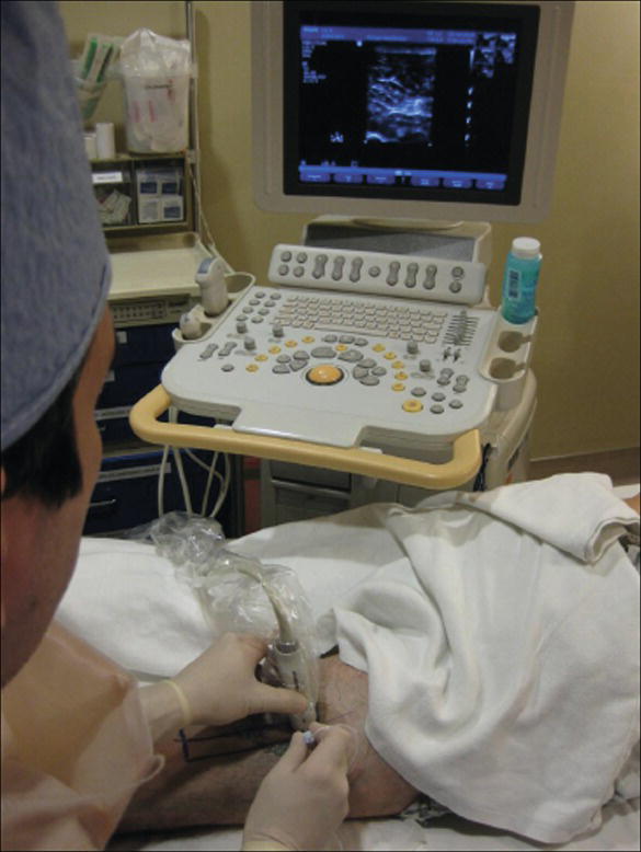
FIGURE 41.12. A block being performed using an advantageous ergonomic arrangement of operator, patient, and US machine. The picture is taken over the anesthesiologist's shoulder to show how he is able to see the US image without turning his head. If necessary, he can check the position of his hands, the needle, or US transducer relative to each other or the patient with a quick glance down while still maintaining a view of the US image.
Proper Use and Maintenance of Ultrasound Equipment
Preparation for Use
To prepare the US machine, turn the power on (do this early, as some machines require a few minutes for the software to boot up), enter the appropriate patient data for billing and study retrieval purposes, and ensure the appropriate US probes are available, functional, and clean. Make sure that adequate US gel (both sterile and nonsterile) and sterile probe covers are available. Some prepared US probe covers include sterile US gel in the packaging. Water-based surgical lubricant can also be used as US gel if US gel is not immediately available.
Ask the provider what kind of procedure the US machine will be used for and on what anatomical site, including the side, if appropriate, of the patient it will be performed. If possible, position the machine on the side that allows best visualization of the screen, and select the proper probe and presets. Set the TGC sliders to the neutral position. Depending upon the type of procedure, improve efficiency by gathering any other necessary equipment (e.g., block kits, vascular access kits, gloves, and gowns).
Following Use
Once the exam or procedure is complete, ensure all wanted images will be stored under the correct patient name. It is helpful to locate the save button prior to starting the procedure. It is typically easy to find, and one push of the button will store all images and videos recorded for the patient. Make sure that any pictures taken and saved have been printed if necessary. Some institutions have systems in place, which allow images to be sent to the electronic medical record. Printed pictures for the medical record should be secured on the appropriate institution-specific form. If one is not available, a progress note form is acceptable. Affix a patient label on the form to ensure that the image is charted and billed appropriately. The machine and transducers used should be wiped down between patients as explained in the following section. Time between patients is a good opportunity to restock supplies specific to the procedure. In regard to the US machine, make sure that the US gel (sterile and nonsterile), sterile sheaths, or other means of probe cover are available for the next procedure. In order to improve efficiency, if the next patient name is known, this is a good time to enter demographic data, choose a preset, position the machine, and set up for the next procedure.
Maintenance
It is important to maintain the US machine in optimal condition and prevent potential damage as much as possible. Probes should be properly stored and protected when not in use. They are expensive and can be easily damaged. Become familiar with any potential maintenance agreements your department has with the manufacturers of the machine. They often will provide a loaner machine for use while your department’s machine is either repaired or maintained. Some manufacturers recommend preventative machine maintenance and cleaning by a service representative on a quarterly basis. Contact information is frequently placed somewhere on the machine by the sales representative.
Inspect the US machine daily. It may be easiest to do this at the beginning of the day. Ensure that all connections such as probes and printers are plugged in properly. Evaluate the integrity of connection cables wires, and transducers. Check the printer and make sure an adequate amount of printer paper remains. The machine and transducers should be wiped down, preferably with a nonalcohol-based solution. Alcohol-based solutions are effective, but may decrease the life span of the transducers. Make sure to wear gloves when cleaning the US machine and transducers with hospital-grade cleaning wipes or cleaning solution. These wipes and solutions contain harsh chemicals that can be caustic and irritating to the skin if direct contact occurs. Before each procedure, make sure to have some form of sterile covering available for the transducer whether in the form of a sterile sheath or large clear adhesive. A brief inspection and thorough cleaning should occur between each patient and at the end of the day. Transesophageal echocardiography probes should be sterilized between patients as per your institution’s protocol.
Any problems encountered with the machine should be documented, and any significant issues should be reported to the manufacturer representative as soon as possible. They can be helpful in organizing smooth and timely service to your machine and quick return for use. Some facilities choose not to obtain a maintenance agreement with the manufacturer of the machine, and instead choose an internal bioengineering department to handle all maintenance issues. US technology continues to evolve and many of today’s machines contain software that can be upgraded periodically, according to the manufacturer’s recommendation. Staying vigilant is the key to preventing, or catching a problem early with your machine. Knowing the proper channels of communication will ensure timely service of your machine in order to avoid affecting appropriate patient care because a machine, or probe, is not available.
Summary
US is a powerful tool that can be used by anesthesiologists for a wide variety of procedures. Equipment may initially appear complicated, but after obtaining a basic understanding of the physics of US imaging, machine controls, terminology, and maintenance, you will be able to use equipment properly and assist during US exams and procedures effectively and safely.
Review Questions
1. To adjust the brightness of the US image, which of the following controls on the US machine should be adjusted?
A) Frequency
B) Focus depth
C) Depth
D) Gain
E) Focal zone
Answer: D
Adjusting gain affects the brightness of the image. Gain may be adjusted overall or in specific areas of the image (near/far, TGC, or LGC). The other choices can all be adjusted on most US machines and are useful to optimize image quality, but they do not directly affect the brightness of the US image.
2. When using US to visualize deeper structures, which of the following adjustments are most likely to improve image quality?
A) Decreasing depth, increasing frequency, decreasing focus depth.
B) Increasing depth, decreasing frequency, increasing focus depth.
C) Increasing gain, increasing frequency, decreasing focus depth.
D) Decreasing gain, decreasing frequency, decreasing focus depth.
Answer: B
To image deeper structures, there must be sufficient depth to the image to include the structure(s) of interest. Lower frequency US waves travel better through tissues, and though they have by definition lower resolution than higher frequency US waves, they can reach deeper structures better as they are less subject to tissue attenuation. Increasing the focus depth so that the US beams are focused at the depth of the structure(s) of interest will improve the quality of the image at that depth. Increasing or decreasing gain settings may or may not improve the ability of see deeper structures, depending on the specific sonographic properties of the particular structure.
3. Which of the following is not a patient safety measure for US-guided procedures?
A) Use of probe covers or other barriers, as well as cleaning the transducer between procedures to prevent cross-contamination.
B) Continued contact with the manufacturer for inspection, calibration, software updating, and maintenance of US equipment.
C) Use of color Doppler with every US exam to identify vessels before guided placement of in-plane needles.
D) Archiving of images for possible future review as part of a teaching file of continuing quality improvement.
E) All of the above are necessary for patient safety.
Answer: C
Color Doppler is not the only method for identification of blood vessels and is not always reliable. Recall that Doppler signal is directional and is not seen at all if flow is directly underneath the probe and not flowing either toward or away from the probe. Color is not used in all US exams or needle placements. Prevention of cross-contamination between patients will help reduce the risk of infection complications. Ensuring proper function of US equipment will help to reduce the risk of error due to malfunctioning equipment and prevent risks of electrical shocks or other injuries; ongoing contact with manufacturer recommendations regarding maintenance and updates is essential for this. Storage of images for periodic review can be helpful to determine potential causes of ineffective procedures or complications.
4. With regard to probe manipulation during US-guided procedures, the mnemonic “PART” stands for
A) Polarity, activity, response, timing.
B) Power, arc, resonance, tension.
C) Pressure, alignment, rotation, tilting.
D) Positioning, access, reference, time.
E) Procedure, access, rotation, traction.
Answer: C
The “PART” mnemonic stands for pressure, alignment, rotation, and tilting. These are four attributes of the position of the US probe, which the operator can use to optimize ultrasound view of underlying structures. The other choices are random words starting with the same letters.
5. US image formation at its most fundamental level involves a visual representation of the
A) Direct measurement of the natural resonant frequencies of varying tissue compositions averaged over time.
B) Indirect measurement of the electromagnetic waves emitted by movement of ions across cellular membranes.
C) Generation of sound waves by a piezoelectric element, the reflections of which are measured by the element and processed by a computer.
D) Direct measurement of microscopic oscillations of molecules, filtered through a white noise generator.
E) Generation of low-intensity ionizing radiation that penetrates tissues of varying density in a characteristic pattern.
Answer: C
This US image is a graphical representation of US waves that have been emitted from and received by the US transducer. The waves are generated by a piezoelectric element that vibrates when exposed to an electrical current. Waves are emitted for only a small percentage of the time, and the transducer is in the “receive” mode the majority of the time. The other choices are nonsense except for “E,” which describes the physics underlying roentgenograms (also known as X-rays).
6. The Doppler effect can be utilized in US scanning to delineate which of the following structures.
A) Peripheral nerves
B) Blood vessels
C) Bone
D) Muscle
E) Air-filled spaces
Answer: B
Doppler (or color) imaging uses a physical phenomenon known as the Doppler shift to measure movement. This phenomenon can be used to measure flow through blood vessels. The Doppler effect is displayed on the US screen as color, and the color scale can be used to show how fast blood (or any other substance) is moving toward or away from the US transducer. Therefore, structures such as blood vessels, which contain fluid with flow will display color allowing for delineation from nonblood vessel structures, which will not display color. Tilting the US transducer (discussed later) toward or away from the direction of flow may improve the color signal.
SUGGESTED READINGS
Antonakakis J, Sites B. The 5 most common ultrasound artifacts encountered during ultrasound-guided regional anesthesia. Int Anesthesiol Clin. 2011;49(4):52-66.
Arbona F, Khabiri B, Norton J. Ultrasound basics for the busy novice practitioner. Int Anesthesiol Clin. 2011;49(4):34-51.
Neal JM, Brull R, Horn JL, et al. The Second ASRA and Pain Medicine evidence-based medicine assessment of ultrasound-guided regional anesthesia: executive summary. Reg Anesth Pain Med. 2016;41(2);181-194.