
This diesel cooker replaced the old gas oven and hob and is now ready for some heavy duty cooking.
Diesel cooker
Although liquid petroleum gas (LPG) is safe and convenient when used properly, some boatowners worry about having a gas system on board. If your boat runs on diesel, you can use the boat’s fuel supply for cooking. One advantage of diesel is that it is readily available around the world.
There are various forms of diesel cooker, from the drip-feed types that operate in a similar way to the old-fashioned ‘Primus’ stove, to the latest ceramic hob types, which look similar to a modern electric hob.
You first need to remove the old gas oven and hob and think about modifying the galley to suit your new equipment. The amount of work required to do this, however, will depend upon the old equipment and how it was installed. Check how well your new installation fits into your galley space. You will need a direct fuel feed to the cooker from the fuel tank and will have to insert exhaust outlets above the waterline.
This diesel cooker replaced the old gas oven and hob and is now ready for some heavy duty cooking.
Installing the exhausts
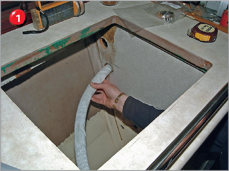
Exhausts can be run a maximum of approximately 4m (13ft) from the cooker, and it is important to keep the outlets as far above the waterline as possible. A substantial curve in the pipe (‘swan neck’) is also needed to prevent water coming into the system. For this installation, the exhaust had to run from the galley into the wheelhouse to achieve a height above the waterline. The exhaust runs through holes cut in the half bulkheads from the cooker to the outlet positions and through holes cut in the hull.
If you need to cut holes in the hull, use a bead of waterproof sealant on both sides of the cork gasket to ensure a watertight seal on the exhaust outlets when bolted in. Wipe off any excess sealant with paper towels and methylated spirit.
Installing the fuel feeds
The oven and hob need their own dedicated fuel supply direct from the diesel tank, whether it is the main engine fuel tank or a small auxiliary tank. In this installation, the feed is from the main tank. The fuel piping specified is a 3mm (⅛in)-diameter copper tubing and one run is sufficient to feed both the oven and the hob, with a tee at the galley end to allow both units to be connected. The maximum run for fuel piping is 8m (26ft), unless the system is gravity fed (downward pipes).
If the tanks are mounted higher than the oven or hob, you should fit a solenoid valve at the tank end to make sure fuel cannot run into the units when not being used. The valve switches on automatically with the hob or oven so there is no need for any additional switches. In this installation, the tops of the tanks were higher than the galley so the solenoid valve was installed into this system.

Place the new hob in position to ensure it will sit on the edges without any additional filling in. This hob will have a brushed stainless steel cover to fill the space taken up by the old hob.
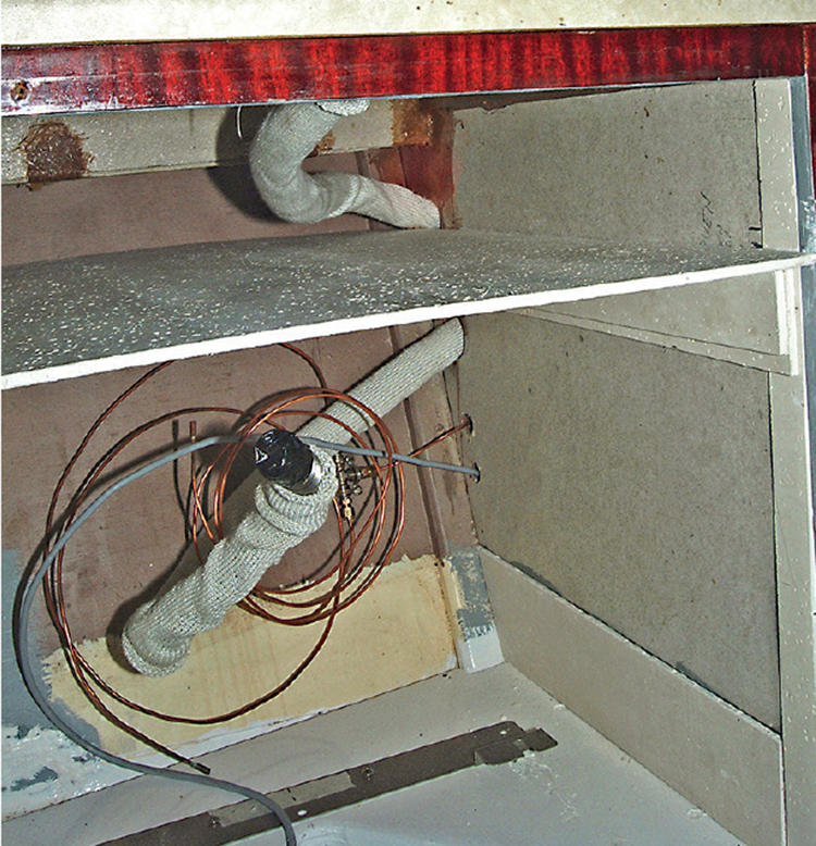
Run the fuel piping through to the galley end and connect it using compression fittings at the tee. At the same time, also run through the cable controlling the solenoid valve. At the tank end, mount a new fuel pick-up pipe into the top of the tank incorporating the solenoid valve and optional fine filter, and connect the piping. Use clips to support both the fuel piping and exhaust throughout their length.

The solenoid valve mounted on the engine service tank.
The compartment lined with heat-insulation board. The oven-mounting bracket can also be seen.

The front clamp is fitted onto the oven to complete its installation.
EXHAUST INSTALLATION
1 of 4 You may need to cut holes in the partition to allow the exhausts to be run through to the exhaust outlet positions.
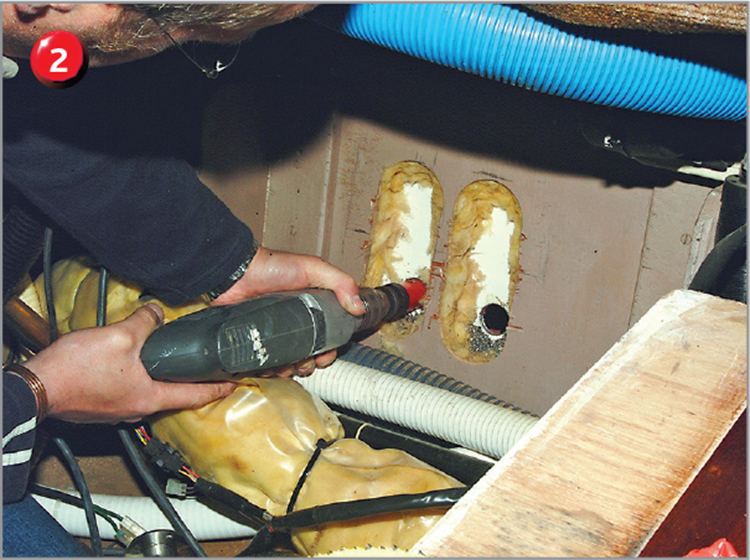
2 of 4 Drill holes in the hull for the exhaust outlets, with the internal ply sheath cut open to allow room for the ‘swan necks’.

3 of 4 Connect the exhaust pipework, covered in a sheath of heat-resistant insulation.

4 of 4 The exhaust piping for hob and oven ready for connection to the appliances. The fuel feed from the solenoid valve on the tank runs into a tee piece.
Preparing the heat-resistant housing for the oven
Because of the heat generated by the oven you need to insulate the housing with fire-resistant board. This is available from builders’ merchants and is generally used for insulation around wood burning stoves and ranges. When the hob is mounted above the oven the heat from the oven must be prevented from warming the underside of the hob, otherwise the built-in overheat protection will switch the hob off.
The first job is to build in a shelf for the oven to sit on and then paint it prior to fitting the oven. A ventilation opening in the shelf also assists airflow. Measure the position for the cooker rear mount and screw the mount in place. Place the rear feet of the oven into the mount.
Power cables and solenoid
The size of cable required will depend on the length of the run – for example 4mm ( in) has been used for a maximum run of 4m (13ft). The cables are run from the hob and oven housing through to the fuse board ready for connecting. The hob and oven are prewired separately with plugs and sockets to allow easy connection and disconnection.
As both the hob and oven operate the fuel cut-off solenoid (a sensor that switches off the fuel if there is a leak), the solenoid requires a relay switch in the circuit to allow them to operate independently. This can be mounted in any position to allow convenient connection of the solenoid operating feeds. The relay control current from the hob and oven is via a prewired plug. (The solenoid power supply can be fed from either the hob or the oven, whichever is more convenient.)
Installing the oven
The controls for the oven and hob are mounted remotely in any chosen position. Before putting the oven and hob into place the control connections are plugged into their appropriate sockets. For this installation the controls are mounted on the front of the galley above the oven. The simple brushed stainless steel panel was made up by a local engineering company.
With the oven standing in place the first connection to be made is the power lead. Next fit the exhaust and securely tighten the hose clip. The fuel piping can then be connected. With the oven set up, slide the fireboard, which divides the hobs from the oven, into place. The final job on the oven is to fit the front clamp, which locates onto the front feet.

Apart from fitting the stainless steel cover, the hob installation is almost complete.
Installing the hob
The hob is secured with brackets bolted onto each side with further bolts screwed up under the worktop. Once the hob is in position, the corners are marked so that self-adhesive rubber seal strips can be fitted and the hob mounting brackets fitted and tightened followed by the exhaust and fuel connections. Finally, the control panel connections are plugged in and the panel is screwed into position. Care is needed not to catch the wiring between the cabinet and the panel during the final fitting.

Oven and hob controls connected into the loom before fitting the front panel.