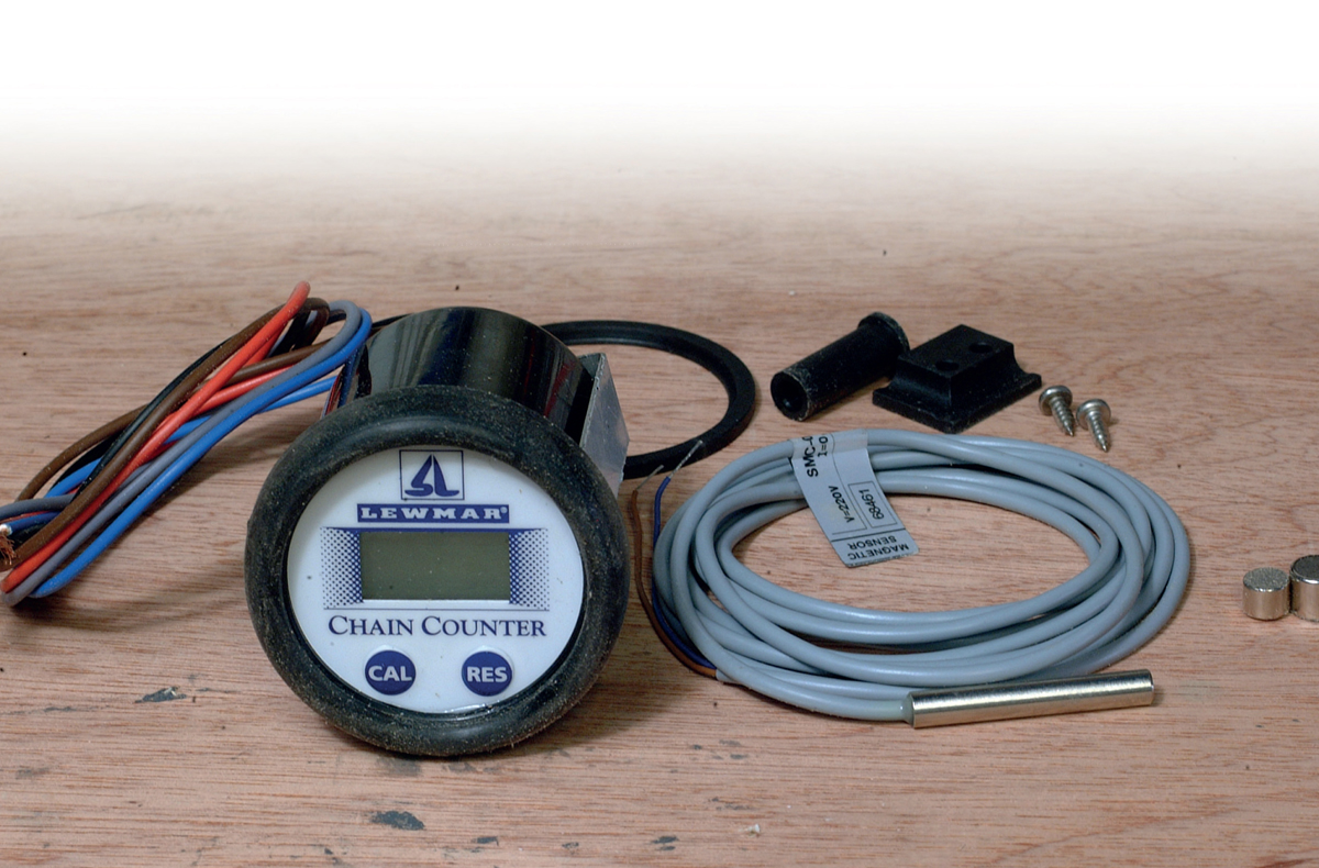
The chain counter kit with gauge, sensor, magnets and brackets.
Chain counter
A chain (or rode) counter is used for measuring the amount of chain running when it is out of sight of the helm. This gadget is able to ‘count’ the amount of chain being hauled or veered around the gypsy (the wheels that allow the chain to engage), and this is displayed on a gauge. Some chain counters are more straightforward to install than others, as not all windlasses are equipped to work easily with a rode counter.
You should be able to fit chain counters to any make and type of windlass, but each installation will vary depending on the style of windlass. The sender consists of a sensor and a magnet. Each time the magnet passes the sensor it ‘knows’ that the gypsy has made one turn, which equates to a certain amount of chain being hauled or veered. The display on the gauge can be adjusted to suit the circumference of the gypsy and therefore the amount of chain moved with each revolution.
The first step is to decide the position of the sensor. It will need to be protected from physical damage, while also being close enough to the gypsy to sense the magnet passing close to its face.
A suitable position is also needed for mounting the magnet within the gypsy. If there are no appropriate external mounting positions for the sensor, it should be mounted somewhere inside. To fit a chain counter, you can purchase chain or rode counter sets, which normally include a gauge, sensor, sensor holders and two magnets of different sizes.
The chain counter kit with gauge, sensor, magnets and brackets.
Dismantling the windlass
The first job is to take the windlass apart. Remove the clutch nut, chain stripper and clutch insert from the drive shaft of the windlass. Also remove the two drive pins that are found between the clutch insert and drive shaft, followed by the chain control arm and gypsy. Turn the windlass over and remove the six cover screws before lifting off the side cover.
Planning the sensor position
Lift out the various drive gears to make room to examine the interior to find the best mounting point for the sensor. The most suitable position for this particular unit is below the gypsy, which means the sensor has to be mounted at an angle to clear the large drive gear. It is important to ensure there is sufficient thickness on the gypsy to accommodate the magnet – perhaps behind one of the chain ‘teeth’.
Fitting the magnet in the gypsy
Use a centre punch to mark the position of the hole for the magnet on the side of the gypsy. Drill the hole with an 8mm ( in) bit or whatever size corresponds to the size of the magnet, taking extreme care to ensure the drill only goes far enough in to accommodate the magnet, with an additional 1mm (
 in) for sealing with epoxy.
Clean the hole with methylated spirit and a paper towel prior to sealing in the magnet with epoxy. Fill the hole with epoxy before inserting the magnet, which is placed into the hole and pushed down gently so that the adhesive squeezes up around it. This ensures the hole is completely filled, with no empty voids remaining to weaken the chain ‘tooth’. Place a final drop on top and clean off the residue.
FITTING THE SENSOR AND MAGNET

1 of 6 Unscrew the clutch nut, chain stripper and clutch insert from the drive shaft. The method will vary depending on the make of windlass but is generally an easy task.

2 of 6 Unbolt the case securing machine screws. Once again, this will vary between makes but the securing screws or bolts are generally fairly straightforward to locate.

3 of 6 This shows the position chosen for the chain sensor on this windlass. Find a position that is protected from the elements and from physical damage.

4 of 6 Install the magnet into the gypsy by mounting one through the chain gripping teeth. This allows enough depth for the hole to be drilled without passing right through.
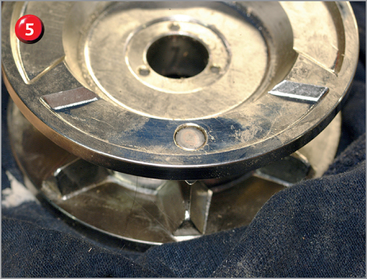
5 of 6 The magnet can be seen sitting in place in the drilled hole. Pour epoxy into the hole. This forces some of the epoxy out but ensures that the hole is filled.

6 of 6 The magnet is totally sealed into place. The epoxy that surrounds the magnet ensures that maximum strength is returned to the area where the hole was drilled.
Installing the sensor
The next step is to install the sensor so that the magnet passes over its face on every revolution. You need to accurately measure from the centre of the gypsy to the centre of the magnet, and transfer the measurement to the body of the windlass. After marking and centre-punching, place the drill bit in the correct position for drilling (in this case the hole has to be drilled at an angle). Check the position of the sensor to ensure it won’t foul the gears inside or protrude too far.
To mount the sensor, create a simple 1mm (in)-thick stainless steel bracket in the vice and drill it to accept the mounting clamp that was supplied with the kit. Drill a countersunk hole in the base of the windlass body for mounting the sensor holder. Clean the inside of the hole for the sensor face with methylated spirit and paper towel, ready for installing the sensor on its mount and bolting it into place. Make any final adjustments to the sensor on its mount and tighten the bolts. Use epoxy to seal the sensor into the body inside and out.
The sensor cable
Run the sensor cable out of the bottom of the windlass body through the same aperture as the motor cables. It is a good idea to apply polyurethane sealant onto the sensor cable to bond it to the windlass base and prevent any possibility of it moving and getting snagged in the gears. Once the sealant has cured make sure that the cables can’t come anywhere near the gearing before finally closing the case.
THE SENSOR INSTALLATION

1 of 6 Drill a hole to install the sensor. This hole is drilled at an angle, so begin with a small drill bit and gradually increase the bit size until the hole is the required diameter.

2 of 6 Bolt the sensor into place on its bracket, ensuring that it lines up correctly with the drilled hole and finally tighten the securing nuts and bolts.

3 of 6 Seal the sensor into place with epoxy. Ensure that the hole is completely filled to prevent water entering the casing and also ensure the sensor is protected.

4 of 6 Pass the sensor through the same hole as the motor cables (if there is enough space). Push silicone sealant into the hole around the cables to make the seal.
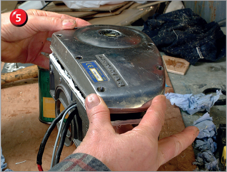
5 of 6 Refit the case onto a bed of polyurethane sealant. This model of windlass has no gasket and just relies on the sealant. Other models may be sealed by a gasket instead.

6 of 6 The finished job with the sensor and magnet protected behind the gypsy. The new chain counter can now have a final test to ensure everything is in position.
Reassembly
Grease the gears and reassemble them before closing up the case with a bead of sealant around the edge (as there is no gasket for this joint). Place the side cover over the main shaft located on the two alignment pegs and press down onto the casing. Apply thread-locking fluid (an adhesive) to the threads of the Allen head machine screws, and insert them into their places in the casing.
Tighten them a little at a time, until all are secure and sealant has squeezed out all around the joint. Reassemble the gypsy, stripper, clutch insert and nut in the reverse order to their removal. The reassembled windlass looks no different now it is complete, apart from the additional sensor wire.
Finally, fit the gauge close to the windlass operating switch in any convenient position.

The final positioning of the gauge for the chain counter (also see inset).
TIP
Calibrate the chain counter before use to ensure that it is reading accurately. You can set whatever measurement system you wish (such as feet or metres) via the settings on the gauge.