Figure 12.1 Storage Tiers Management service in the Task Scheduler

For those who have had some time to play with Storage Spaces in Windows Server 2012, I bet you are excited about the new changes in R2. But before we discuss them, let’s do a quick recap of Storage Spaces for those who are new to this feature.
Storage Spaces was introduced in Windows Server 2012 as a native feature. Remember, this is not RAID but is something new that was designed for full-blown enterprise use. The basic function of Storage Spaces is to allow you to take just a bunch of disks (JBOD) and configure them in a pool. From here you can create virtual disks (the actual storage space) and volumes with fault tolerances of various degrees. This type of configuration gives you great flexibility.
Imagine not having to invest in a large, expensive storage area network (SAN) or in the specialized training that your administrators would need to configure and maintain it. A core goal of Storage Spaces is to provide a cost-effective solution for mission-critical storage. Storage spaces and pools are designed to grow on demand. Here is a list of just some of the features in Storage Spaces that are included in Windows Server 2012:
In this chapter, you will learn to:
Since this book is about Windows Server 2012 R2, we’ll now tell you what’s new in storage. Microsoft has included technology in Storage Spaces that you previously saw only in expensive storage arrays. The following sections detail the new technology.
There are several classifications of disks in today’s storage world, including Serial Advance Technology Attachment (SATA), Serial Attached SCSI (SAS), Solid State Drive (SSD), and Fibre Channel. Choosing the correct storage for the job is essential. For example, if you need a file server, SSD is not a good choice. SSD was designed for speed, not capacity, and because file servers generally need capacity and not speed, SATA, which was designed for capacity rather than speed, in this case may be a better match.
In Windows Server 2012 R2 you can have a maximum of two storage tiers, essentially a fast tier and a slow tier. These tiers use SSD in the fast tier and SATA in the slow tier automatically. The really clever thing here is that an administrator doesn’t have to decide up front where to place the data. The Storage Tiers Management Service will automatically analyze the data on your disks in slices of 1 MB. It has two categories for assignment: hot spots and cold spots. Hot spots are areas of the data that are accessed frequently; the assumption here is that since this is active data, it is a “hot topic.” Cold spots are the opposite: data that has not been accessed regularly. After the analysis, hot spots will be promoted to the SSD tier, and any identified cold spots will be assigned to the SATA tier. The analysis happens daily at 1:00 a.m. by default, but you can configure it if you like; see Figure 12.1. But if a file needs to be on the fast tier all the time, the administrator can “pin” the file to the fast tier.
Figure 12.1 Storage Tiers Management service in the Task Scheduler
Write-back cache refers to how data is written to disk. Data is written to the cache first and will be stored there until it is about to be overwritten; at this point it will be flushed to disk and committed. In general, writing and storing data in cache gives better performance and is considered another type of memory. If an app is writing to the cache, it can hand off its I/O handle quickly and get back to other tasks. Certain workloads traditionally don’t like write-back caching because when the app writes data, it must be written to disk to avoid corruption. Hyper-V, for example, requires write-through. Tiered storage can be used in conjunction with a virtual disk (not VHD/VHDX in relation to Hyper-V and virtual machines in this case, but a virtual disk from a Storage Spaces perspective) to absorb any spikes in writes. The fast tier can then be used to overcome the spike and allow Hyper-V to use write-back caching.
When a disk fails in a traditional RAID set, if you have a hot spare (a disk that can instantly take over the job of a failed disk in a RAID set), this hot spare will kick in and the RAID array will start rebuilding the data on this disk. A performance impact on the disk subsystem is inevitable during the rebuild because all the data is being written to a single disk. The paralyzed repair process in Storage Spaces is a little different. If a disk fails, the remaining healthy disks that have suitable capacity take ownership of the data that was stored on the failed disk and will serve users’ requests across all available spindles. Since all disks are now helping out, there should be no performance impact. The repair process can bring in the hot spare or the administrator can replace the failed disk, and in the background the disk can be brought back into the storage space.
Originally, hard disks used a 512-byte-per-sector format, and with this came limitations in storage size and performance. With ever-increasing demand on capacity and speed, a change was needed, and over the course of a few years 4K sector disks became standard. However, software (such as file system utilities, operating systems, and database engines) was not necessarily quick to catch up. Most drive manufacturers shipped 4K sector drives but emulated 512-byte sectors for compatibility. Obviously, this requires a bit of overhead because the entire 4K sector is read into memory, modified, and then written back. Since there is a degree of manipulation happening, there is also a performance impact, which is acceptable in this case.
With native 4K support, the data storage industry no longer emulates 512-byte sectors, which means the performance impact is gone.
The following list shows some of the apps and scenarios for 4K sector support:
Master boot records are special areas located at the beginning of the partitioned space on a disk. They contain information on the underlying partition structure and some chained boot code to allow the operating system to start. Master boot records stored their block address as 32 bits. Originally, a 512-byte sector drive with a block address of 32 bits was limited to 2 TB. This obviously is no longer acceptable. So the industry went to 4K sectors, and now drives have a maximum capacity of 16 TB. It seems like we are getting there, but considering that in today’s infrastructure we could be looking at petabytes of data, terabytes just doesn’t seem to cut it.
The GUID Partition Table (GPT) provides a 64-bit addressing structure. With a 512-byte sector drive you could have 9.4 zettabytes (9,444,732,965,739,290,426,880) of data. Currently, the GPT supports a maximum disk and partition size of 8 ZB.
I can envision you now rushing to convert your drives to GPT, and you would be right! But be careful; not all operating systems support booting from GPT partitions using standard BIOS. See the following link:
http://en.wikipedia.org/wiki/GUID_Partition_Table
The Unified Extensible Firmware Interface (UEFI) is designed as a direct replacement for the legacy BIOS system. It essentially does the same job but adds functionality like diagnostics and repair of computers with operating systems deployed. UEFI is designed to support booting from GPT, and Windows 2012 R2 fully supports the UEFI BIOS.
In all the years I have been computing, this has been one of my staples. CHKDSK has been with us for many generations of DOS and Windows, and it is (for me, anyway) great to see this tool upgraded.
One of the biggest problems that faced CHKDSK before its upgrade was its direct relationship to the number of files on a volume. The larger the number of files, the longer it took to run. Another problem that constantly plagued CHKDSK was that if it detected a problem, it usually had to dismount the volume, rescan everything, detect the problems all over again and then fix the problem. As you can imagine, with large volumes this took a long time, and in our current always-on culture, downtime is simply not acceptable.
The CHKDSK code has been upgraded, and the NTFS health model has also been redesigned. We’ll discuss these upgrades in the next few pages, but they essentially lead to the simple conclusion that CHKDSK is no longer needed in its former capacity.
Although this feature of NTFS has been around since Windows Vista, the number of issues that it can detect and fix online has greatly increased. This in turn has decreased the actual need for CHKDSK because most issues will be self-healed. And if they self-heal, the volume doesn’t have to go offline.
In Windows Server 2012 you can verify an actual corruption. Sometimes errors occur because of memory issues, but this doesn’t necessarily mean the disk is corrupt. Now, because of online verification, you can invoke a check. A new service called Spot Verifier is triggered by a file system driver to perform this check, as shown in Figure 12.2. It operates in the background and does not affect system performance.
Figure 12.2 Spot Verifier service

Once you find a real issue, an online scan of the file system is triggered. This scan is designed to run in conjunction with the operating system and will run only when the system is idle or when utilization is low. Once it finds the problem, it logs it for offline correction.
Because you have logged where the issues are, you don’t have to scan the entire file system again when you begin the offline process. This essentially means that when you do take a volume offline to repair the issues, it takes seconds to repair rather than potentially hours. This quick fix is called Spotfix. If you are using Cluster Shared Volumes, there is no downtime, giving you always-on volumes.
With these new improvements, the CHKDSK runtime is no longer based on the number of files but rather on the number of corruptions. Because you can repair so many issues online (with CSV always online), CHKDSK is becoming less required. Figure 12.3 shows the new options that are available in CHKDSK.
Figure 12.3 New CHKDSK options
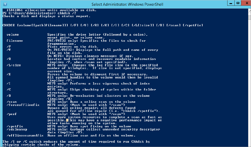
The new options are /scan, /forceofflinefix, /perf, /spotfix, /sdcleanup, and /offlinescanandfix. As you can see, they relate directly to the new health model described previously.
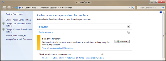
We must stress at this point that another key goal of upgrading CHKDSK was to ensure that users are kept informed of any corruption. Part of the reason was to allow users and administrators to stop actively running CHKDSK to verify the file system; now there is simply no need. The system uses the Action Center included in Windows to notify a user or administrator of file system corruption and recommends an action. See Figure 12.4 for the results of a sample online scan.
Figure 12.4 Message in Action Center for online scan
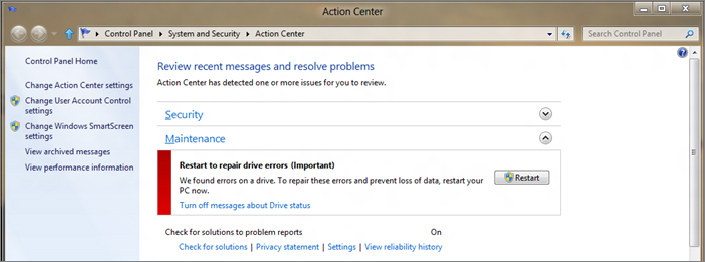
In Figure 12.5 you can see that if the issue cannot be repaired online, the Action Center will ask you to restart the computer to allow an offline repair.
Figure 12.5 Message in Action Center for offline scan
In Windows Server 2012 R2, the concept of Storage Spaces is essentially the same as what was released in Windows Server 2012, which we discussed at the start of this chapter. The exceptions are the new features we introduced earlier and now we will go into further detail about.
Microsoft runs multiple cloud services. I’m sure you’ve heard of Windows Azure or Office 365. Imagine all the lessons Microsoft learned during the deployment, setup, and day-to-day operations of these environments. Also imagine that if Microsoft had to buy multimillion-dollar storage networks to cope with the ever-growing need for storage in cloud-based environments, how crippling this would be to a cloud-based environment.
Microsoft applies all this knowledge to the new technologies they release, including Storage Spaces. Microsoft needed a cost-effective way to increase storage and maintain essential features found in storage area networks, hence the birth of Storage Spaces. As cloud services develop, you will see improvements in Storage Spaces such as those you have seen between the releases of Windows Server 2012 and Windows Server 2012 R2.
One of the really interesting things about Microsoft technologies is the familiar interface that they provide for managing their products. You are usually given two options: the GUI and PowerShell.
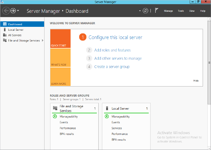
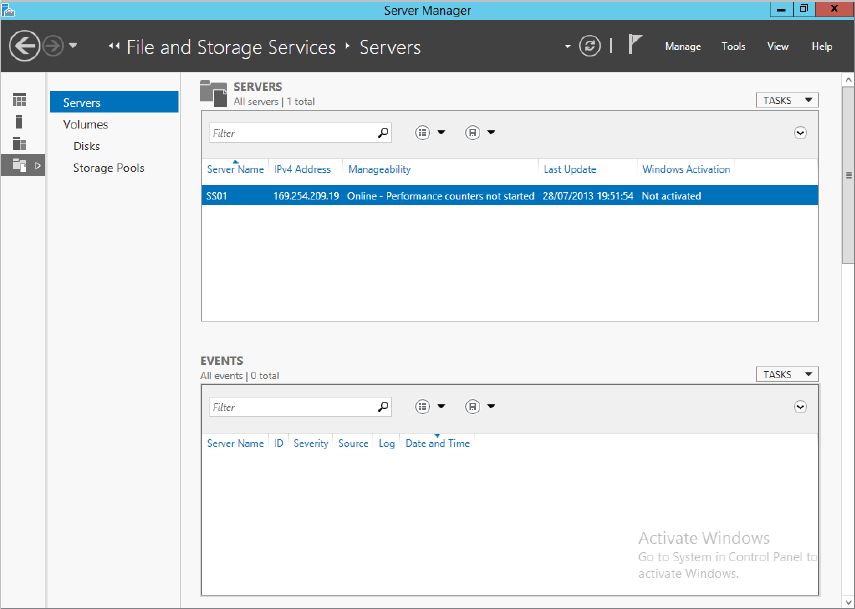
Although the Microsoft Management Console (MMC)—the traditional console for most of the management plug-ins—still exists, most features within Windows Server 2012 R2 are managed via Server Manager, as shown in Figure 12.6. Storage Pools is enabled by default on all systems and can be found as a subfeature under File and Storage Services.
Figure 12.6 Server Manager, File and Storage Services
Once you choose File and Storage Services, you will see all the related options to this menu, including Storage Pools, as shown in Figure 12.7.
Figure 12.7 Suboptions for File and Storage Services
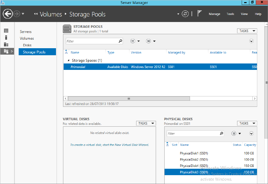
Clicking Storage Pools will bring you into the main configuration. Take a look at Figure 12.8.
Figure 12.8 Storage Pools configuration

This is the main configuration window, it is split into three main areas:
As mentioned, you can use PowerShell cmdlets to quickly provision Storage Spaces. Some administrators prefer to work with a command-line environment when administering servers. Personally, I like to mix them.
Windows Server 2012 R2 has a new PowerShell module called Storage, which contains all the PowerShell cmdlets you need to work with Storage Spaces.
In Windows Server 2012 and above, a PowerShell module is automatically imported when you attempt to call a cmdlet that is part of that module. To review the cmdlets available to you under the Storage module, open an elevated PowerShell window and type get-command –module Storage. In Windows Server 2012 R2, there are 102 cmdlets available to you. Not all are storage pool related.
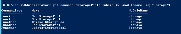
Hopefully you are familiar with PowerShell and understand its verb/noun structure. If you base what cmdlets you are looking for on Figure 12.8, this would mean you are looking for cmdlets related to physical disks, virtual disks, and storage pools. To help you identify the cmdlets for each of these, try typing get-command *StoragePool* |where {$_.modulename –eq "Storage"} and examine the result. Figure 12.9 shows the expected output; each cmdlet has its own set of options, which you can see by using get-help cmdletname.
Figure 12.9 Storage cmdlets
We are not going to go through this here, but we are going to show you some sample output from a couple of the cmdlets. For example, type get-storagepool and observe the output. Now type get-storagepool |fl * and see the difference. FL is an alias in powershell which standards for Format-List, the * option determines which properties you want to display, in this * stands for All properties. The output is shown in Figure 12.10. Repeat for the cmdlets get-physicaldisk and get-virtualdisk and observe the output.
Figure 12.10 Sample output for get-storagepool

Storages Spaces is an extremely powerful feature, and as we have mentioned, storage spaces bring many benefits to an organization. They are also simple to configure. No specialized training is required.
In the next few pages we’ll walk you through the process of creating a storage space and show you how simple it really is. The general process is as follows:
We will show you how to create a storage pool via the GUI and PowerShell. First, however, we will give you a quick introduction to our lab. We have a single server with multiple physical disks, two 100 GB SAS drives, two 150 GB SAS drives, and one 300 GB SATA drive.
When you create a storage pool you must decide on the physical disks you want allocated to the pool. It is important to think in terms of what the pool will be used for and, now with the storage-tiering feature, what type of disks should be part of the pool.
To create a pool, follow these steps:
Figure 12.11 Creating a new storage pool
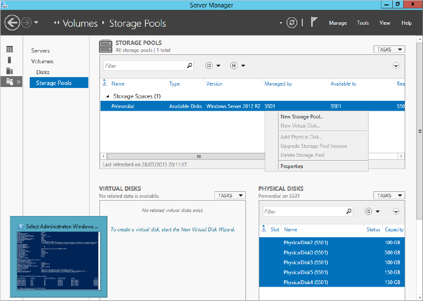
Figure 12.12 Naming your storage pool
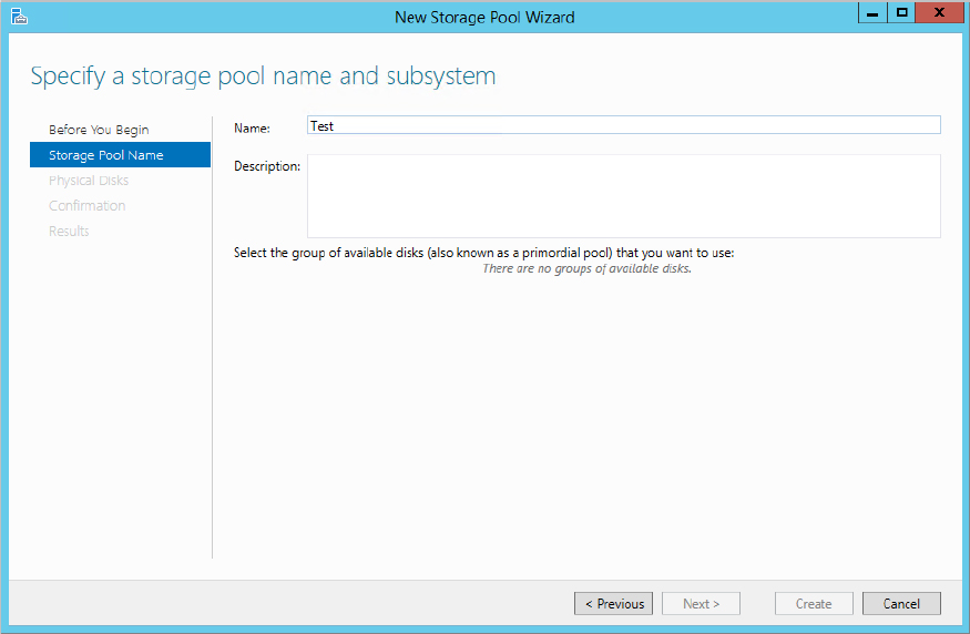
Figure 12.13 Selecting disks for the storage pool

Figure 12.14 Disk allocation options
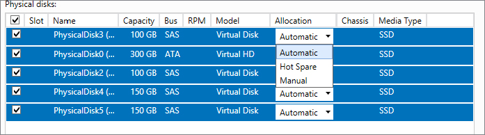
Figure 12.15 Changing the drive allocation type in PowerShell

Figure 12.16 Reviewing the configuration options before creating a pool
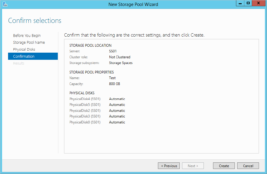
Figure 12.17 Storage pool created successfully

Congratulations on creating your first storage pool.
As with all technologies, there are some limitations to storage pools, and although the technology is powerful, it most certainly is not optimal for every situation. With that in mind, let’s look at the limitations:
Essentially, a storage pool is a logical container for the disks. For example, in our demo environment we have several disks ready to be assigned to a storage pool. In the Disk Management screen shown in Figure 12.18, you can see all the physical disks listed before we pooled them.
Figure 12.18 Unallocated disks in Disk Manager

After we added the disks to a storage pool, we refreshed Disk Manager. As you can see in Figure 12.19, they all disappeared. Disk 1 still remains as this is the OS disk and it always will be and you will never be able to include it in a storage space. Where did they go? Remember that a storage pool is a container. You need to create virtual disks in order to see the volumes in Disk Manager again.
Figure 12.19 Drives no longer appearing in Disk Manager after being added to a storage pool

We mentioned earlier that everything you can do in the GUI you can do via PowerShell. We will now show you how to create a storage pool using PowerShell:
Figure 12.20 Displaying available physical disks
$drivestopool = (Get-physicaldisk |where {$_.CanPool –eq $True})Figure 12.21 storagesubsystem cmdlet
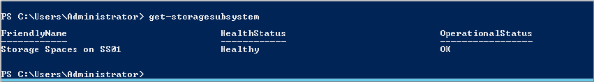
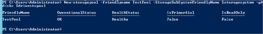
$storagesystem = (get-storagesubsystem).friendlynameNew-storagepool –friendlyname TestPool –StorageSubSystemFriendlyName $storagesystem –physicaldisks $drivestopoolFigure 12.22 Output of PowerShell when creating a new storage pool
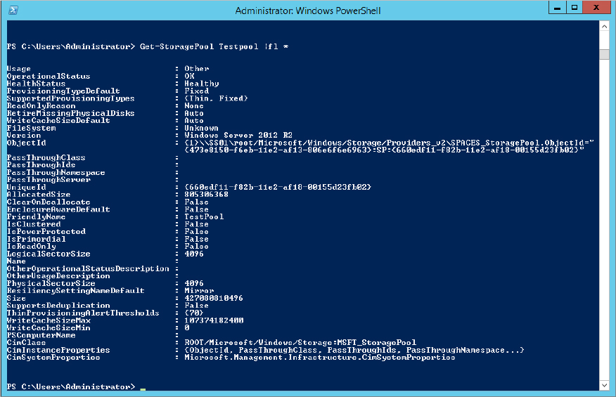
Get-StoragePool TestPool |fl *Figure 12.23 Output for Get-StoragePool cmdlet
From the outset of this chapter we have made it clear that when we reference a virtual disk in relation to storage space, we are not talking about VHDX for a virtual machine. In fact, unless you place a virtual machine in the storage space or use it as an iSCSI target store, you will not see a VHD anywhere.
Virtual disks are essentially disks that you carve out of your storage pool. You previously created a pool for your physical disks, and we showed you that from a Disk Manager perspective all the disks disappeared because they now belong to the storage pool. In order to use some of the space contained within your storage pool, you have to create a virtual disk. It is not directly related to a physical disk in the storage pool, but it is representative of a chunk of space you are allocating out of the storage pool. How that chunk comes into existence depends on the options we will discuss next.
One of the great things about virtualization in general is that you maximize the use of the hardware. For example, previously many organizations had one server role, which was a waste, but now you can have multiple roles that are completely isolated assigned to one server. Hopefully you are familiar with virtualization in general at this stage. A similar concept exists in storage pools and virtual disks.
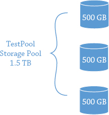
As we have already said, storage pools are essentially logical containers for a set of physical disks that you want to aggregate. The virtual disks will be presented to a server for use as a volume. If you have three physical disks of 500 GB each combined in a storage pool, you have the potential for 1.5 TB of space. See Figure 12.24.
Figure 12.24 Storage pool allocation
Pretty cool. (We’re not taking into account redundancy just yet, because we will explain this shortly.) Now a system administrator gets a request from a new application team, and they require 2 TB of space for their application. However, when the system administrator reviews the projected growth, they realize that the 2 TB won’t be needed upfront, which is good because there is no budget for more disks. Sound familiar? The dilemma is what to do about it.
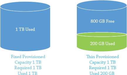
One of the first choices you have with virtual disks is whether they are fixed or thin provisioned:
Figure 12.25 Fixed and thin-provisioned disks
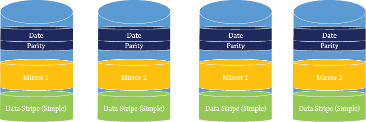
Next, you need to decide on the layout of the virtual disk. There are three resiliency options, as follows:
Figure 12.26 gives you a visual representation of the different layouts you can potentially use. As you will see in green the data is written across all disks. In yellow you will see if we write the data to one drive in a 4-drive mirror it will get written to a second disk. Finally in blue we show you data is written across all disks but parity information is written with it to allow for recovery.
Figure 12.26 Virtual disks layout
The next step is to create a virtual disk. The easiest place to create the virtual disk is within the Storage Pools console of Server Manager, as shown in Figure 12.27.
Figure 12.27 Storage Pools console
 New Virtual disk, as shown in Figure 12.28.
Figure 12.28 Creating a new virtual disk

Figure 12.29 Select a storage pool to use for creating a virtual disk
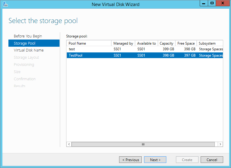
Figure 12.30 Naming and describing the virtual disk
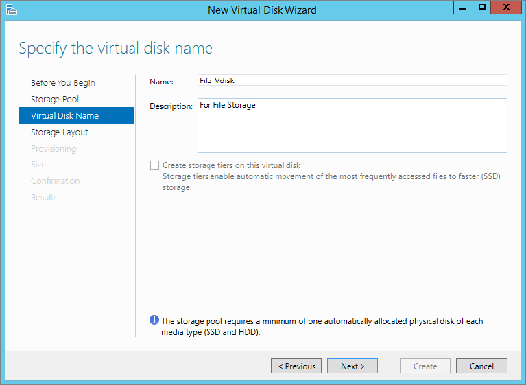
Figure 12.31 Storage layout for virtual disks

Figure 12.32 Provisioning type for the virtual disk

Figure 12.33 Setting the size of the virtual disk
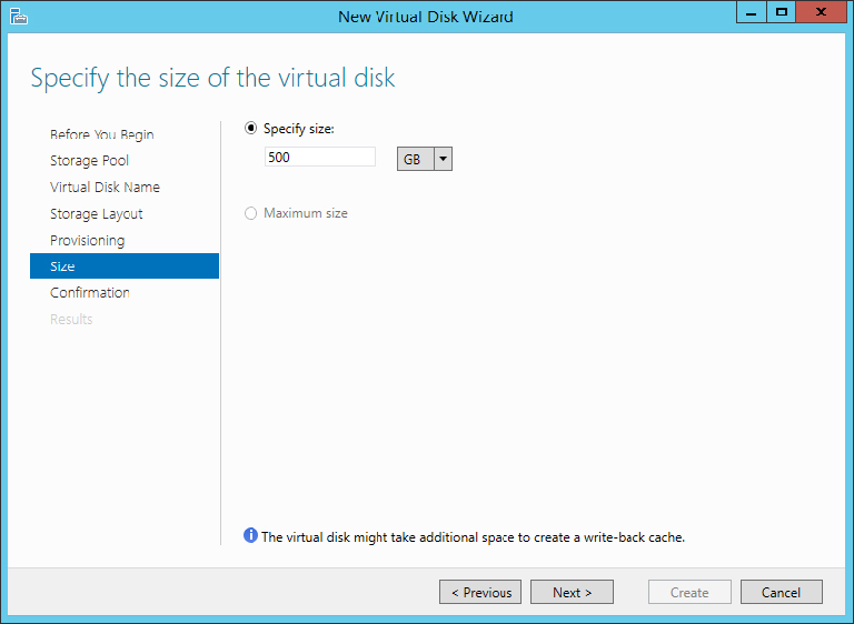
Figure 12.34 Results screen for the new virtual disk

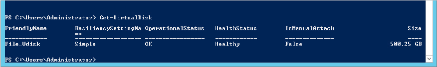
First, let’s use PowerShell to look at the virtual disk we created in the previous example using the GUI. In Figure 12.35 we use the Get-VirtualDisk cmdlet to retrieve all information on virtual disks that we’ve created. As you can see, we have created only one, the 500 GB virtual disk.
Figure 12.35 Output of Get-VirtualDisk
To create a new virtual disk you need to use the cmdlet New-VirtualDisk. But you need to know the storage pool friendly name before you start. Do you remember the command for getting the storage pool friendly name?
Once you have the friendly name, follow these steps:
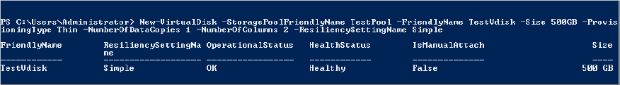
$sp = (get-storagepool).friendlynameNew-VirtualDisk –StoragePoolFriendlyName $sp[1] –ResiliencySettingName Simple –Size 500GB –FriendlyName TestVdisk –ProvisioningType Thin –NumberofDataCopies 1 –NumberofColumns 2Figure 12.36 Sample output from creating Vdisk in PowerShell
Again, as an exercise, view the disk in Disk Manager.
If you have ever provisioned a standard physical disk and created a volume and formatted it, then this should be very familiar territory.
There are several ways you can create volumes. Disk Manager and Diskpart are the two you are most familiar with, and there is absolutely nothing wrong with creating the volume from one of these if you so wish. However, for this example and to show you that you can do everything you need in relation to storage spaces directly from the Storage Pool UI, we will show you how to create a volume from there.
In Figure 12.37 you can see the Storage Spaces UI, and under Virtual Disks you can see File_Vdisk, which we created earlier.
Figure 12.37 Storage Spaces UI with our newly created virtual disk
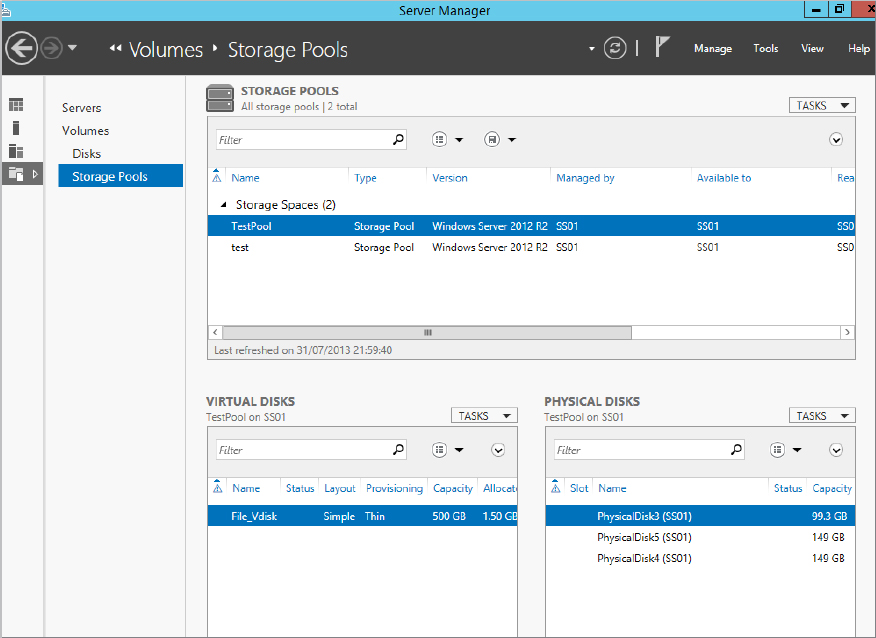
Figure 12.38 Creating a new volume from a virtual disk
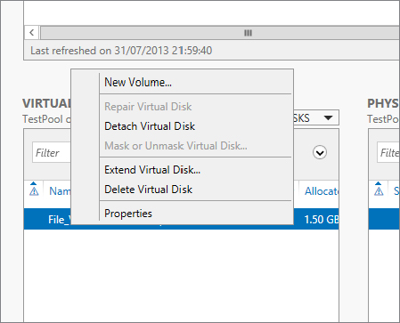
Figure 12.39 Selecting the server and virtual disk

Figure 12.40 Setting capacity for the volume

Figure 12.41 Selecting a drive letter for the volume

Figure 12.42 File system settings

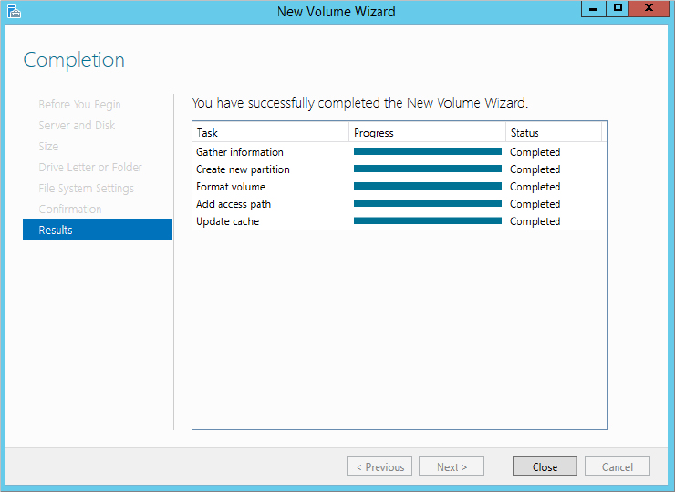
Figure 12.43 Results screen for creating the volume
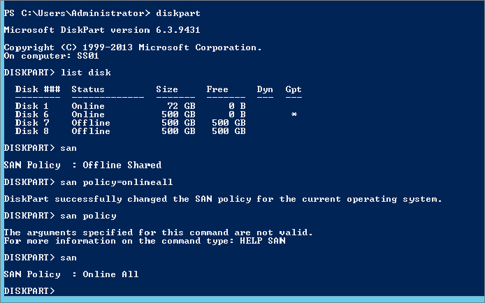
By default, when you add a physical disk or a VHD or even a new virtual disk, it will always be in an offline state. Normally this is OK, but in a cloud environment always having to bring the disk online is an extra step you could do without. In the command-line utility Diskpart you have the ability to configure an option so that if you create a virtual disk, it will automatically come online.
To set the policy status for SAN disks to Online, in an elevated command line type the following:
Diskpart "san policy=OnlineAll"See Figure 12.44 for sample outputs of running Diskpart and setting the SAN policy to Online.
Figure 12.44 Sample output for setting Diskpart SAN policy
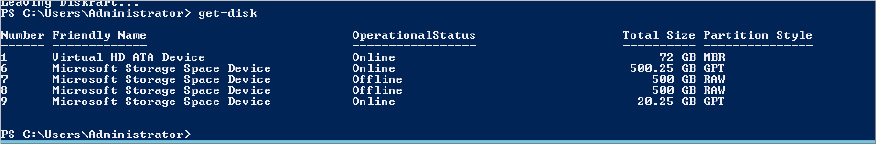
As with everything, the old command-line tools are being replaced with PowerShell. Can you guess the cmdlets used to find out what disks are offline and set them online?
First, let’s use get-disk to figure out what state our disks are in. Figure 12.45 shows a sample output for get-disk, and as you can see, there are two disks offline.
Figure 12.45 Output for get-disk
Get-disk |where {$_.operationalstatus –eq "Offline"}Figure 12.46 Bringing all disks online using PowerShell
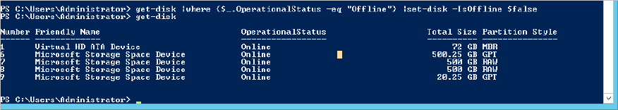
Get-disk |where {$_.operationalstatus –eq "Offline"} |set-disk –isoffline $falseWe have brought you through creating a storage pool, a virtual disk, and volumes for your environment. One of the things we mentioned at the beginning of this chapter was storage tiers. They can be of huge benefit to an environment because they allow you to split up your storage and charge-back based on the resources that the end users require. Essentially, if the end users require high-speed storage, you can allocate and bill accordingly; if they don’t, you can allocate low-end storage to serve their needs. If your company does charge-back, this will be of benefit to all end users because storage spaces will automatically move the more frequently accessed data to the fast storage tier and the less accessed data to the slow tier.
Since you are now familiar with the Storage Spaces console, you will notice that there is no place to configure storage pools within the UI. This feature can be configured only via PowerShell.
We’ve already created our storage pool named TestPool, so let’s use this as the friendly name.
As we’ve already said, you can create only two tiers in Windows Server 2012 R2. Solid State Drive (SSD) and Hard Disk Drive (HDD) are the two media types the system recognizes.
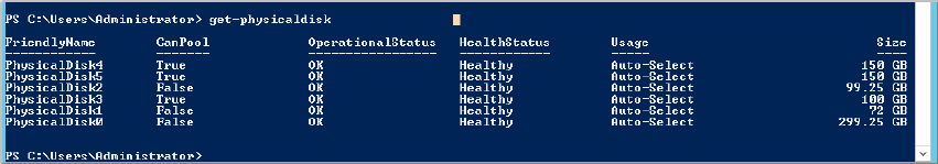
In our lab if we run the PowerShell cmdlet get-physicaldisk, we get the output shown in Figure 12.47.
Figure 12.47 Sample output of get-hysical disk for creating storage tiers
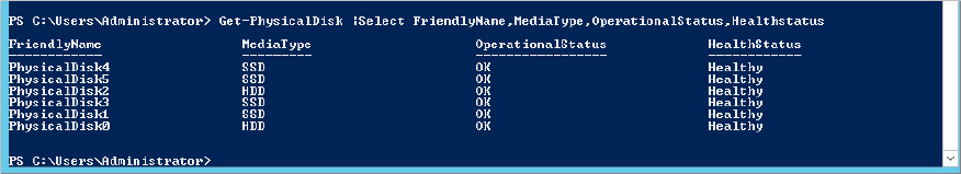
As you can see, we have SSD and HDD drives in our environment. Now we’ll create our storage tiers. We are going to create two tiers in our example (which is also the maximum supported), and then we’ll create a virtual disk that will be allocated across the tiers. We will then partition and format the disk for use.
Using the cmdlet New-StorageTier, here is the syntax to use for creating the SSD pool. We have to store it in a variable for later use:
$ssdtier = new-storagetier –StoragePoolFriendlyName "TestPool" –FriendlyName SSD_Tier –Mediatype SSDFor the HHD tier we use the following syntax:
$hddtier = new-storagetier –StoragePoolFriendlyName "TestPool" –FriendlyName HDD_Tier –Mediatype HDDThe next step is to add a virtual disk and tie it to the storage tiers. Before you ask whether you can remap an existing virtual disk to a storage tier, the answer is no.
With that in mind, we’ll create a new virtual disk, which we will tie to our storage tiers. Here is the syntax to use:
New-VirtualDisk –StoragePoolFriendlyName TestPool –FriendlyName Tiered_VDisk –StorageTiers @($ssdtier, $hddtier) –StorageTierSizes @(10GB, 50GB) –ResiliencySettingName SimpleFigure 12.48 shows the output of successfully creating a disk.
Figure 12.48 Output of creating a virtual disk in storage tiers
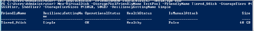
Most of the options should be familiar from creating a virtual disk earlier. However, we have two options related to creating a virtual disk in a storage tier:
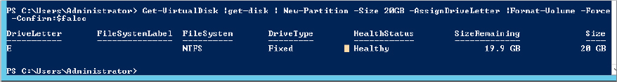
From here you would need to create a volume as before for storing data. We’ll show you a quick PowerShell trick you can use to create a 20 GB volume on the disk and format it all in one line! Here is the syntax:
Get-VirtualDisk | Get-Disk | New-Partition –Size 20GB –AssignDriveLetter | Format-Volume –Force –confirm:$falseSee Figure 12.49 for the output of the command. Now you can navigate to the drive letter and copy a file.
Figure 12.49 Creating a new partition and formatting it in PowerShell
Take a moment to review the properties of the virtual disk we previously created. In Figure 12.50 notice how the capacity is split because we set it between the different tiers.
Figure 12.50 Properties of a tiered virtual disk

Now we’ll show you how to use one of the last major features of Storage Spaces in Windows Server 2012 R2, the write-back cache. As with storage tiers, you cannot enable this via the GUI; it must be done via PowerShell. Remember, the write-back cache can help speed up applications because writing to cache is quick and doesn’t have to wait for storage to catch up to commit the write.
Take the PowerShell command we used to build our previous storage tier and modify the name and the StorageTierSizes options. Then add the –WriteCacheSize option with a size setting; in this case you want a write-back cache size of 2 GB:
New-VirtualDisk –StoragePoolFriendlyName TestPool1 –FriendlyName Tiered_VDisk –StorageTiers @($ssdtier, $hddtier) –StorageTierSizes @(20GB, 70GB) –ResiliencySettingName Simple –WriteCacheSize 2GBVoilà You have now created a virtual disk that will use storage tiers, with write-back cache enabled.
The final thing we discussed about storage tiers at the start of this chapter is that every night at 1:00 A.M. it will run a job to reprioritize the storage and move around what needs to be in the fast tier versus the slow tier.
In Task Scheduler, choose Task Scheduler Library Microsoft Windows Storage Tiers Management. Task Scheduler lists a job called Storage Tiers Optimization, as shown in Figure 12.51.
Figure 12.51 Storage Tiers Optimization task

You can modify the task or manually trigger it if necessary.
Storage spaces are incredibly useful for providing scalable and reliable back-end storage. Think of the amount of money a company would have to invest to get the abilities we have already outlined. What would be really useful now is to combine all this powerful storage technology with iSCSI so you can allow remote systems (such as file servers, mail systems, virtualization clusters, and the like) to also benefit from these features.
iSCSI requires a few elements to be configured in order for it to present logical unit numbers (LUNs) to remote machines. First, we’ll explain a few items that make up iSCSI from a host server and remote server perspective that you’ll need to know in order to understand the example we’ll use:
This technology is commonplace in most businesses today, and it allows them to create clusters for all sorts of business reasons. In my previous place of employment we used a Windows server with the iSCSI target server to create a Hyper-V cluster to run our production network. In the next section we’ll walk you through an example of setting up the iSCSI target service, creating a virtual disk, and presenting it to a remote system.
By default, the iSCSI target service is not enabled. You must add it, and you’ll do this via PowerShell. The syntax for adding the Windows feature iSCSI Target server is:
Add-windowsfeature FS-iSCSITarget-Server –IncludeManagementToolsA server reboot may be required after adding the feature, so make sure you are in a position to be able to complete the installation.
The iSCSI Target server is a File and Storage Services subfeature, and that means that you can administer it via the Server Manager console under File and Storage Services, as shown in Figure 12.52.
Figure 12.52 iSCSI Target server management
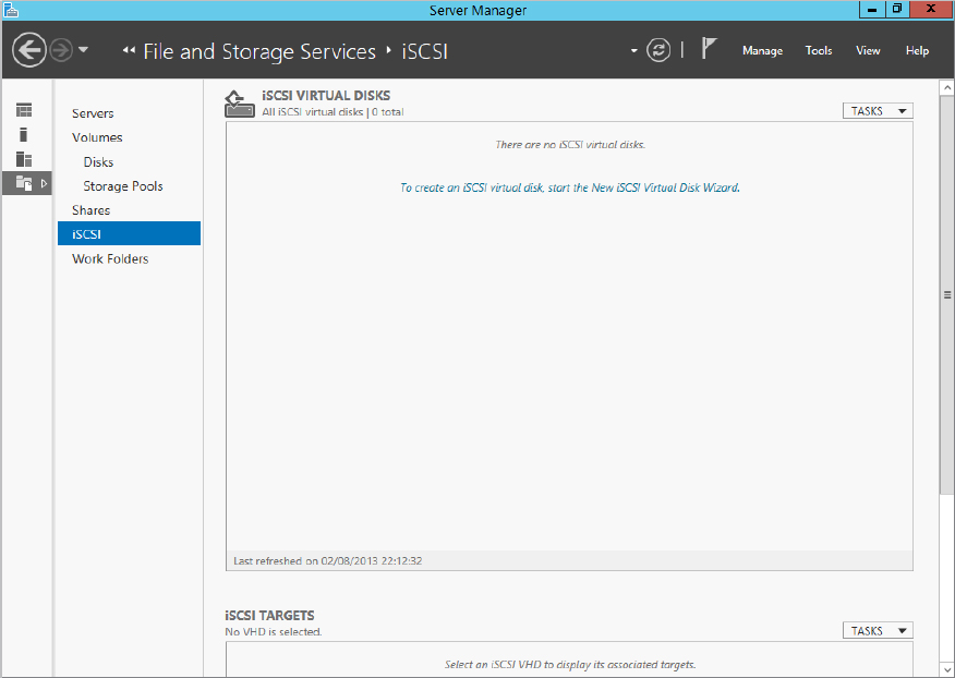
As you can see from Figure 12.52, there are two main screens: iSCSI Virtual Disks and iSCSI Targets. As we have already said, a target will present the iSCSI virtual disks that have been created. (Don’t confuse them with virtual disks in Storage Spaces. They are different; iSCSI virtual disks appear as VHD files on the Target server.)
To demonstrate this, let’s create an iSCSI virtual disk. In our example we will be using the E drive we created earlier from our tiered storage pool. Don’t worry if you haven’t set it up; all you need is a drive and a folder to store the VHD you are going to create.
Figure 12.53 Selecting a server and a volume for an iSCSI virtual disk

Figure 12.54 iSCSI Virtual Disk Name screen

Figure 12.55 New iSCSI target

Figure 12.56 New iSCSI target name

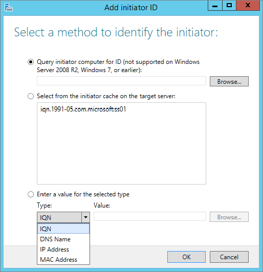
Figure 12.57 Add initiator ID
Do you fancy creating a new virtual disk for iSCSI in PowerShell and presenting it to a target? Here are some sample cmdlets you can use:
New-IscsiVirtualDisk –path e:\newdisk.vhdx –SizeBytes 20GB –Computer name SS01Add-IscsiVirtualDiskTargetMapping –TargetName VMcluster-Target –path e:\newdisk.vhdxDone!
You have provisioned an iSCSI Target server and a new virtual disk, but they are of no use until a client connects to the LUN. Remember that if you set up access lists, you will be able to connect to the LUN only from that specified machine.
Figure 12.58 Locating iSCSI initiator

Figure 12.59 iSCSI Initiator Properties – Quick Connect

Figure 12.60 Successful connection to iSCSI target
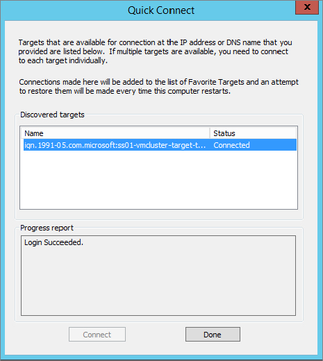
Figure 12.61 Volumes and Devices – Auto Configure
 Disks.
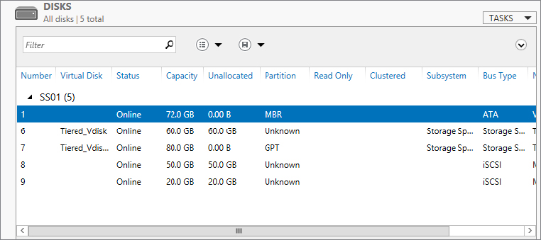
As shown in Figure 12.62, we have two new disks with Bus Type listed as iSCSI. They are now available to format and create standard volumes out of.
Figure 12.62 Displaying newly added iSCSI disks
Network File System (NFS) allows you to share files between a Windows server and a Unix/Linux platform using the NFS Protocol. In Windows Server 2012 the following improvements were introduced:
NFS is used in environments where you have a requirement for file shares in a mixed operating system environment (such as Windows and Unix/Linux). With the improvements in Windows Server 2012, you can now present a share with NFS and SMB at the same time.
A common use for this has been found in some third-party hypervisors using Windows Server 2012 NFS shares as data stores for templates and ISOs.
We’ll now show you how to provision an NFS share. Since we are in a hurry, let’s use PowerShell. Add the NFS service to Windows using the following syntax:
Add-WindowsFeature FS-NFS-ServiceWe have a directory we want to share in our lab under the path E:\shares. We will guide you through this process using the GUI:
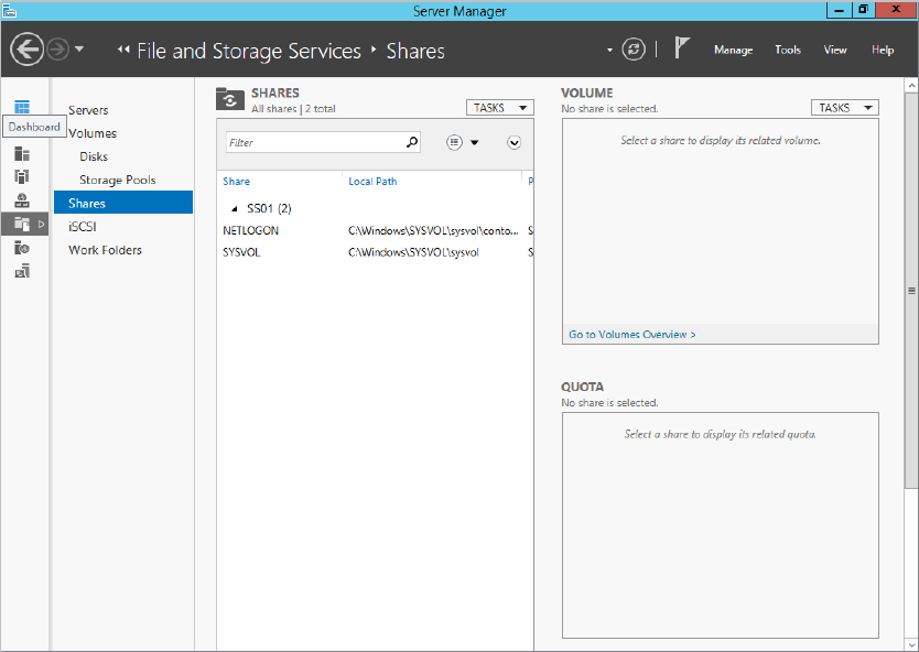
Figure 12.63 Share management in Server Manager
 New Share.
Figure 12.64 New Share Wizard
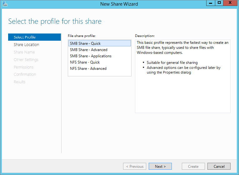
Figure 12.65 Server and path for share
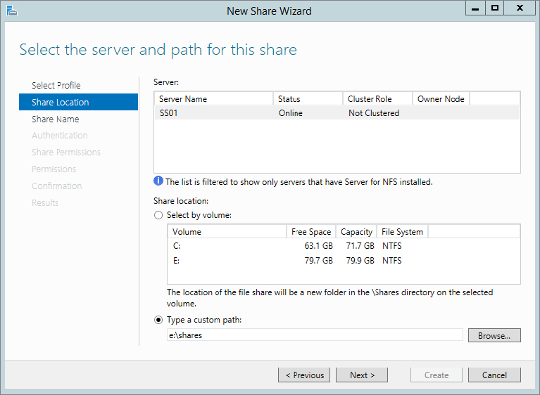
Figure 12.66 Enter a share name.
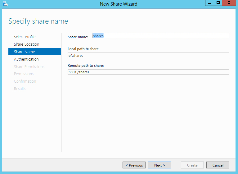
Figure 12.67 Authentication methods

Figure 12.68 Adding share permissions

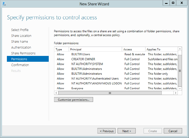
Figure 12.69 Permissions to control access
In our lab we have Linux Mint deployed. By default, we are able to connect to the share, but we get various errors when we try to browse the share or create a directory. Linux Mint, along with many other distributions, requires you to install the nfs-common package before you can read from an NFS share. Follow these steps to install the package:
sudo apt-get install nfs-commonsudo mount -t nfs 192.168.0.1:/Shares /mnt/sharecd /mnt/sharelsOn Windows Server you have created a file called Readme.txt. You should be able to see this file after you issue the ls command. The Readme.txt file is just an example, try placing some of your own files in the share on the windows server and retry the ls command on the linux client.
Windows Server 2012 introduced Data Deduplication as a native storage feature. Data Deduplication is a more efficient way of storing data. With the ever-increasing need for storage in cloud technologies, you can imagine the amount of duplicate files that are stored. Even at home I have several copies of ISO files or virtual hard disks for my USB storage and servers. These files are 3–7 GB each. I’m wasting a lot of storage space by keeping multiple copies and not coming up with a proper library system.
This is a simple example but it brings up another point: the files all have similar parts and they all take up space. Wouldn’t it be cool if you could identify those common pieces, create a single master reference on disk, and then point to it for every other file that has that common piece? You have this ability in Data Deduplication.
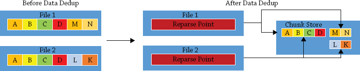
Data Deduplication in Windows uses a concept called the chunk store. A file gets split into variable-size chunks usually between 32 KB and 128 KB; on average a chunk is around 64 KB. These chunks are compressed and stored in the chunk store. Each chunk is stored in a chunk container, which grows to about 1 GB in size before a new container is created. You can view the chunk store and its containers on the root of the volume in a folder called System Volume Information. The folder by default is locked down to just the System account, so you must take ownership of it and ensure that the System account remains in full control. A reparse point replaces the normal file. If the file is accessed, the reparse point shows where the data is stored and restores the file. See Figure 12.70.
Figure 12.70 Data dedup in action
Although not installed by default, Data Deduplication is designed to be easy to deploy. It also has been designed to have zero impact on the users; in fact, the users won’t even notice anything. You can turn on Data Deduplication on any of your primary data volumes with minimal impact on performance. It was designed to not interfere with files that are new or that are currently being written to. Rather it will wait, and every hour it will check for files that are eligible for deduplication. You can reschedule the process according to the needs of your company.
Eligibility for deduplication starts with files that are over three days old (again this is configurable based on needs), and it always excludes files that are smaller than 32 KB, have extended attributes, or are encrypted. If you have other files that you don’t want part to be of the dedup process, this is also configurable.
Deduplication happens on network traffic as well. As traffic is sent or received, it is assessed to see if it can be deduplicated, effectively reducing the potential amount of traffic that has to be sent or received. Unlike storage deduplication, you cannot modify a schedule or data type for the network dedup.
However, there are a few things to be aware of before continuing. Dedup is supported only on NTFS volumes, and you cannot dedup a boot or system drive. In Windows Server 2012 it can’t be used with CSV, live VMs, or SQL databases.
So what’s new in Windows Server 2012 R2 for Data Deduplication? The key focus was on allowing deduplication for live VMs. That’s right; you can dedup the VHDs and VHDXs that your live VMs are using. Primarily you can use it in VDI scenarios, with a further focus on remote storage. With these enhancements you can dedup your VDI environment. It is also worth noting that although it is not supported for other virtualized workloads, there are no specific blockers to stop you from enabling it. As always, the results cannot be guaranteed.
This is an amazing technology to have natively within Windows Server, and it will provide substantial savings in terms of storage for a business. Next we’ll show you how to configure it.
First, you need to add Data Deduplication. You can add this feature using PowerShell. The syntax is as follows:
Add-WindowsFeature FS-Data-DeduplicationThen you can configure it via Server Manager or PowerShell.
We’ll explore the Server Manager method first.
Figure 12.71 Configuring Data Deduplication
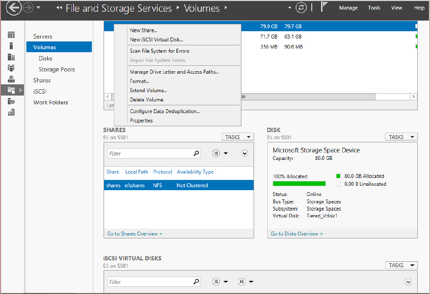
Figure 12.72 Enabling Data Deduplication

Figure 12.73 Configuring New Volume Deduplication Settings
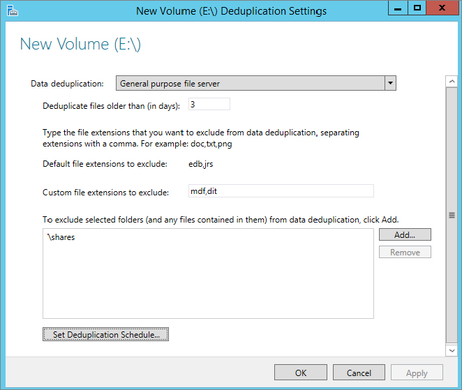
Figure 12.74 Changing the dedup schedule
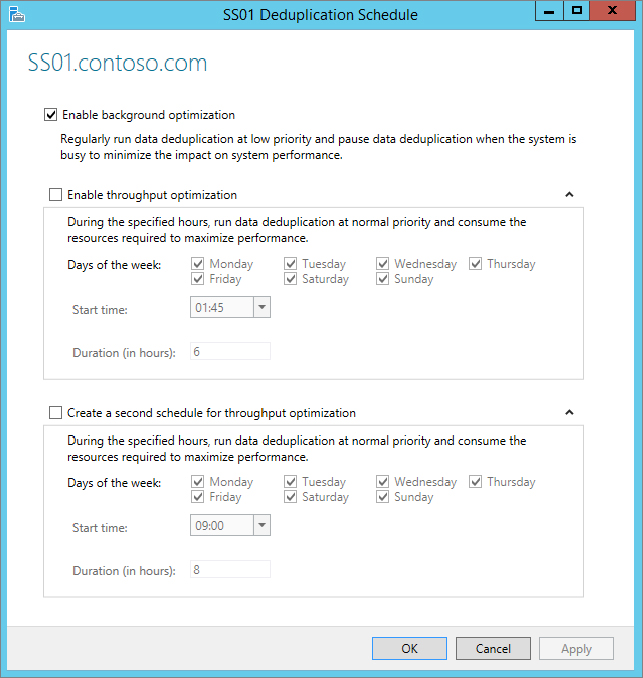
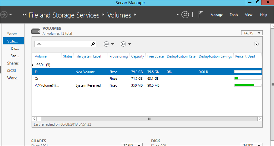
Figure 12.75 Viewing deduplication information in Server Manager
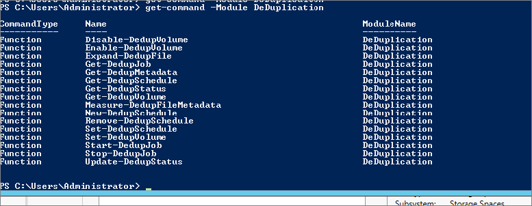
We’ll now show how to work with deduplication in PowerShell. Figure 12.76 shows the available PowerShell cmdlets.
Figure 12.76 PowerShell cmdlets for deduplication
Enable-DedupVolume E:\Figure 12.77 Enabling dedup output with PowerShell
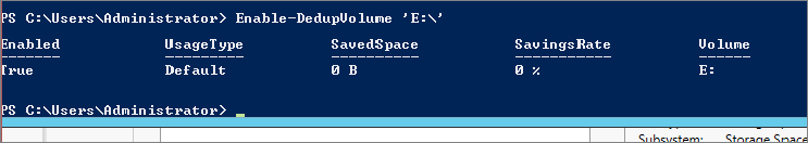
Figure 12.78 Get-DeDupStatus output
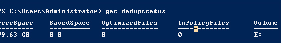
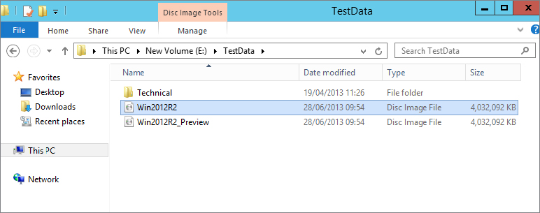
Figure 12.79 Contents of E:\TestData
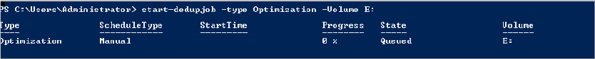
Start-DedupJob –Type Optimization –Volume E:Figure 12.80 Output of Start-DedupJob
 Microsoft Windows Deduplication.
Figure 12.81 Manually invoking BackgroundOptimization
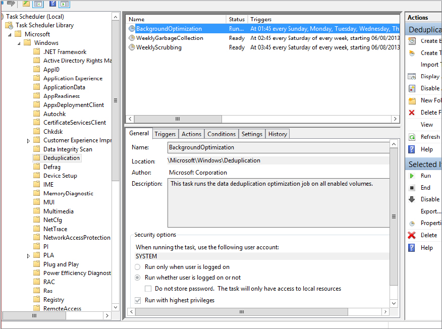
Figure 12.82 Sample output of the Get-DedupJob cmdlet
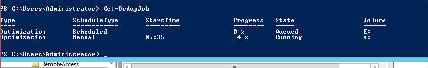
Figure 12.83 Output of Get-DedupStatus while Get-DedupJob is running
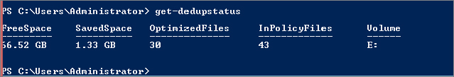
Figure 12.84 Output of Get-DedupStatus when optimization is complete
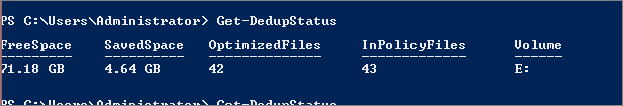
Figure 12.85 Folder properties after running dedup
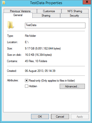
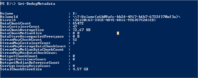
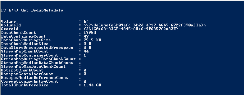
Figure 12.86 Get-DedupMetadata output
As you saw in Figure 12.81, Task Scheduler has two other jobs available that run on a weekly basis. We’ll discuss both of them now. First, we’ll talk about GarbageCollection.
GarbageCollection is configured to run on a weekly basis by default, but you can invoke it as needed. The GarbageCollection job cleans up the chunk store by removing unused chunks, which releases disk space. You can see that it is an important job.
To manually invoke a garbage collection, use the Start-DedupJob cmdlet as follows:
Start-DeDupjob –Type GarbageCollection –volume E:This will queue the job until the system is idle, or you can run the job from within Task Scheduler to accelerate it.
The last thing in relation to dedup that we will talk about in this chapter is volume corruption checks. As you can imagine, the more commonality found in files, the more the chunk store will grow, and the more reparse points that will exist on disk.
Imagine if the disk sector where part of a chunk exists became corrupted. You’d risk losing potentially hundreds or thousands of files. Although this is a rare occurrence, especially if you combine it with resiliency techniques, there is a potential for it to happen. Dedup has some special built-in checks that will prevent this from happening.
For example, dedup has redundancy for critical metadata; it also provides redundancy for the most accessed chunks (if a chunk is accessed more than 100 times, it becomes a hot spot). It provides a log file to record the details of any corruption, and later through the use of scrubbing jobs it will analyze the log and make repairs.
Repairs can be made from the backup of the working copy when referring to the critical metadata or the hot spots. If you have dedupped a mirrored storage space, dedup can use the mirrored data to repair the chunk.
As with optimization jobs and garbage-collection jobs, scrubbing jobs happen on a scheduled basis and can be configured to happen more often than the default of one week.
You can trigger a job with PowerShell using the following syntax:
Start-DeDupJob –Type Scrubbing –Volume E:This will invoke a verification job against the E: drive volume but will check only the entries in the corruption log file.
To check the integrity of the entire deduplicated volume, use the following command:
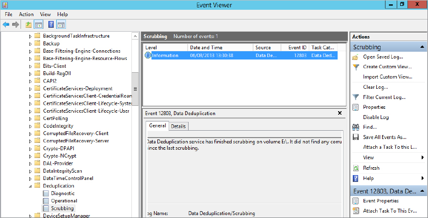
Start-DeDupJon –Type Scrubbing –Volume E: -fullTo review the output of the scrubbing, check Event Viewer. All output for a scrubbing job is stored in Event Viewer Applications and Services Logs Microsoft Windows Deduplication Scrubbing. See Figure 12.87.
Figure 12.87 Event Viewer Scrubbing log
Create a storage pool on a virtual disk. Storage is an ever-growing business requirement. If you were constantly buying SAN solutions to meet this need, it would prove very costly. Also, it is very hard to predict what you may need in a year’s time. How would you manage your storage to get the most out of it and to meet your future storage needs?