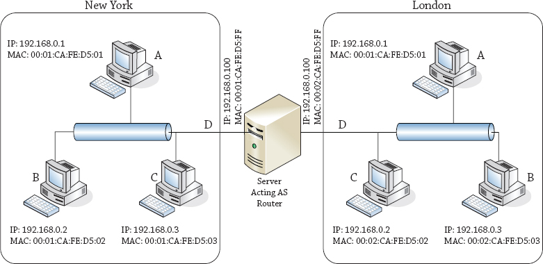
Figure 20.1 A sample network
Why route from Windows? The short answer is because you can, and it will open your eyes to a world previously unseen.
Over a decade ago routers were expensive and it was common for network-savvy companies to use cast-off PCs as cheap routers. For example, by putting a couple of network cards in the PC and installing a copy of Linux, a network engineer could save the company a lot of money on buying a huge chunk of metal from a major network vendor. Even now you can find these distributions lurking on the Internet and still in use in some ISPs.
Routing is a vital part of maintaining a network infrastructure (think about how many VLANs are in your network and how the traffic is routed among them!). It is important to understand how routing works in order to correctly manage your network and the hosts on it. Normally, this is beyond the control of a server administrator, but knowing a little about routing will also help you troubleshoot connection issues on your own hosts and network.
In this chapter, we will take you through the life of an IP packet as it is routed across your network, and we will explore the differences between class-based and classless routing (although these are relatively old concepts, looking at the differences still provides some insight). We will explain how network address translator (NAT) devices allow you to route TCP traffic, and in a brief history lesson, we’ll show how the arrival of Winsock shaped the Internet boom.
We will walk you through the processes of installing the Remote Access role and then show you how to configure a router with NAT. (We will revisit the Remote Access role more in the next chapter.) We will cover how to configure a Windows Server 2012 R2 computer to route IP traffic, and we will discuss tunneling. Finally, you will learn how you can use the knowledge gained from this chapter, and a few common tools, to troubleshoot network communication difficulties.
In this chapter, you will learn to:
The designers of the original Internet Protocol achieved something that goes beyond being merely clever: they made something that is just about as simple as it can be to achieve its purpose. As a result, you will notice that we are not going to tell you how to route UDP or TCP, because IP takes care of all that. We are also not going to tell you how to route Ethernet, because Ethernet doesn’t route; it only communicates on a single subnet.
But this does mean that if you are to understand routing in TCP/IP, you have to know what makes an IP packet move through the system. To this end, we will describe the life cycle of a typical IP packet using a sample network, as illustrated in Figure 20.1.
Figure 20.1 A sample network
In the example IP packet lifetimes in this section, we will be using the network diagram (we assume a subnet mask of 255.255.255.0 or /24 or class C) displayed in Figure 20.1.
The simple case is one where two computers that want to talk to each other are on the same Ethernet segment. Let’s begin at the New York site and start some communication from computer A (IP address 192.168.0.1, MAC address 00:01:CA:FE:05:01) to computer C (IP address 192.168.0.3, MAC address 00:01:CA:FE:05:03). The procedure is as follows:
That list of steps is something you’ll refer to later when troubleshooting connectivity problems, but for now it needs some explanation.
If an IP packet had parents, they would be the source and destination IP addresses. Every IP packet has to know where it’s starting and where it’s going. Imagine getting into your car and not knowing your destination! In IPv4, the packet also needs a name, just in case it gets split into parts by an intermediate router. That way, the receiver will know which parts to put together. Finally, it needs a piece of information that tells the receiver how to treat its data (aka payload), whether it is to be handed to the TCP or UDP stack, or perhaps a different protocol, with abbreviations such as ICMP, IGMP, GRE, and so on. To IP, they are protocols 1, 2, 47, and so on. Most of the time you do not have to worry about this, but you can use tools like Wireshark or Network Monitor to dive into an IP packet to observe all this information.
When a packet is created, all this information—and perhaps some optional parts—is placed into the IP header, and the header and payload are sent to the IP layer of the network stack for forwarding.
The IP layer at any computer or router reads the source and destination addresses and uses them to determine where to send the packet. In this simple case, the source and destination addresses are clearly both on the same subnet, or local link. In that case, no routing is required for the packet.
The IP layer on the source computer has to tell the Network layer (in most cases, this would be the Ethernet driver) to put the packet onto the right network card, with the right network destination and source address, and to do that it must know the Ethernet address (the MAC address) corresponding to each IP address.
From Figure 20.1, it’s clear that the MAC address for the source should be 00:01:CA:FE:D5:01 and that the MAC address for the destination should be 00:01:CA:FE:D5:03, but the source computer doesn’t have this diagram, and since it’s never spoken to C before, it has no idea of its MAC address. All it knows is that the IP address 192.168.0.3 is where this packet needs to go.
This is where the Address Resolution Protocol (ARP) comes into the picture. ARP is an Ethernet broadcast. Technically, all Ethernet packets are broadcast across the whole subnet, but most of them carry a destination MAC address and are discarded by other Ethernet cards when they are received. An Ethernet broadcast packet is meant to be picked up by any Ethernet card.
The ARP packet contains the source MAC address of the requester and the IP address that is being searched for. Every Ethernet card on this segment will receive this request and has to forward it to its IP layer. The IP layer will check to see whether it owns the IP address being requested. The interface that does own this IP address will then respond affirmatively to the ARP request, with a unicast response that identifies itself as the owner of the requested address.
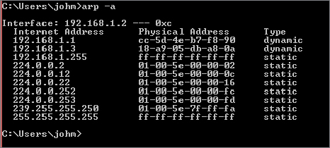
The requester receives this response and adds an association to its ARP table between the IP address and the Ethernet address. You can view this ARP table at any time in Windows using a number of different methods. The easiest to remember is probably the command arp -a, which shows the addresses that have been assigned to network cards, as you can see in Figure 20.2.
Figure 20.2 Displaying the ARP table
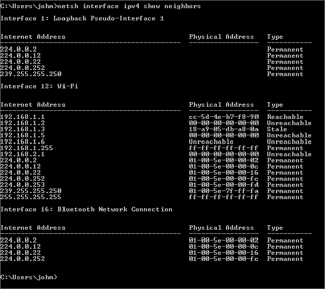
As with most network facilities, you can also see this table using a netsh command, netsh interface ipv4 show neighbors, as shown in Figure 20.3.
Figure 20.3 Using netsh to show the neighbors table
In this example, the IP layer at computer A will create a packet that says, “I am an ARP request packet from the machine at IP 192.168.0.1, and I want to know the MAC address for the interface with IP 192.168.0.3.” Computer A will then “shout” that message to the whole New York segment, most of which will stop what they’re doing, check their IP address to see whether they are 192.168.0.3, and only one (C) will send a response back to A, saying, “I am an ARP response packet from the machine at IP 192.168.0.3, and my MAC address is 00:01:CA:FE:D5:03.”
Occasionally you have to clear a stale entry out of the ARP table; to do this use arp –d inet_addr (where inet_addr is the IP address you want to delete from the table) to resend the broadcast. You can explore further arp options using the help switch arp -?.
In IPv4, the IP layer of every computer on a subnet needs to pause what it’s doing to inspect incoming ARP requests. If you can imagine how annoying it would be for everyone to stop their work every time someone called anyone in the company, that’s roughly what it is like for IPv4 hosts. Switches help mitigate this a bit now, but if you are not careful, you can still have nasty broadcast storms that can bring down your network!
IPv6 discards the concept of broadcast-based protocols—they become multicast-based protocols—and the same is true of Neighbor Discovery (ND), which (among other things) takes over the resolution process from ARP, which is not supported on IPv6.
Rather cleverly, the IPv6 layer will take the last 24 bits of the IP address being queried for and will build a multicast address known as the solicited node multicast address by putting those 24 bits into the placeholder X bits of the destination address FF02:0:0:0:1:FFXX:XXXX. The Neighbor Solicitation message is sent to this address. Because there are more than 16 million possibilities for those last 24 bits, it’s almost certain that this multicast message will interrupt only the Ethernet card and interface that own this IP address.
The Neighbor Advertisement message that comes back tells the requester what MAC address corresponds to the IP address requested—as with ARP, this is kept in a table that is always checked when sending an IP packet, so as to prevent repeatedly requesting the same Neighbor Solicitation message.
To show the neighbors table for IPv6, can you use the ARP command? No, because ARP is strictly for IPv4 only. The way to get the neighbor discovery table that is in use for your IPv6 layer is to run the netsh command, specifically, netsh interface ipv6 show neighbors; a sample output for the author’s Local Area Connection is shown in Figure 20.4.
Figure 20.4 Showing the IPv6 neighbors table

Now that you know who you are trying to talk to, the computer at interface A can finally send the data by building an Ethernet packet, whose payload is the IP packet (IP header and IP payload) and whose header contains the source and destination address, length, and type of protocol (in this case IP). This packet is then handed down to the Ethernet card, which sends it on.
OK, it really isn’t that hard, but we thought it best to approach you with as few confusing issues as possible, which is why we have separated the two parts of packet routing into different sections of this chapter.
Every computer with an IP address is part host, part router. It may not forward packets received from other hosts, as routers normally do, but it most certainly needs to keep a table of routes out from its own interfaces to the rest of the world, exactly as a router would do.
Just as with the ARP table, although you don’t generally want to mess with the table’s contents, you can always view them. Again, as with the ARP table, you can use a couple commands:
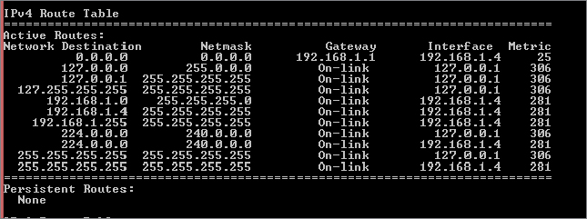
Each command displays the same routing table, but the information and presentation vary. The command route print displays a more class-based routing table and is familiar to many. You should feel comfortable by the end of this chapter with output such as that shown in Figure 20.5, which shows a sample of the IPv4 routing table.
Figure 20.5 Showing the IPv4 routing table with route print
The two netsh interface ipvX show route commands are a little more compact—if you don’t need the interface index table, this format may be more what you need.
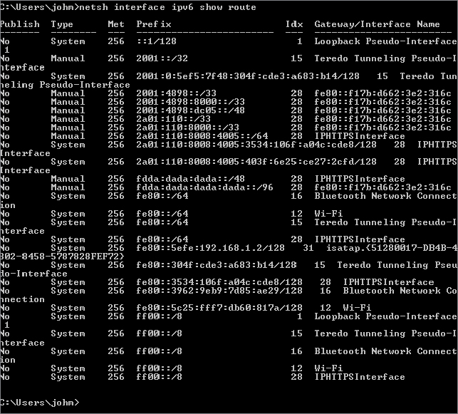
In both of the netsh outputs, the network destinations are in the newer Classless Inter-Domain Routing (CIDR) format, which we will describe in more detail shortly. Figure 20.6 shows the IPv4 routing table, and Figure 20.7 shows the IPv6 routing table. There is little difference between them except for the format and size of the prefix.
Figure 20.6 Using netsh to view the IPv4 routing table
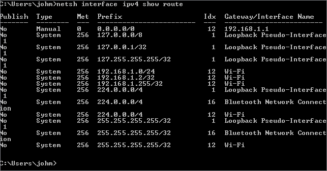
Figure 20.7 Using netsh to view the IPv6 routing table
As you can see, that’s a lot of confusing data to understand.
Let’s pick one of those outputs and analyze it. Because it’s new to everyone, let’s go with the netsh output. This output has six columns—Publish, Type, Met, Prefix, Idx, and Gateway/Interface Name. Here is what each column represents:
When an IP packet is assembled by an application and sent to the IP layer, its destination address is checked against the local subnet link address and mask of every network interface to see whether the destination address is local. You’ve already seen what happens if the address is indeed local—the ARP or ND table gets consulted and, if necessary, refreshed, and the packet is placed onto the appropriate NIC for transmission to its target.
If the address isn’t local, you obviously have to send it through a router. You will find a router to send the packet to, and you will act as if the router’s MAC address is actually the MAC address returned by an ARP query on your destination’s IP address. In fact, in some very strange environments, this is exactly what the routers have been configured to do—respond to every ARP as if the router is indeed the host being searched for. That’s a sign of a dysfunctional network, though, so we’ll say no more about that.
How do you find the right route in the routing table? There are three simple criteria:
Once the IP layer has chosen a routing entry, as we mentioned earlier, it will send the IP packet to the router listed as the gateway in that entry. Of course, that means that the IP layer must use ARP to determine what MAC address corresponds to the IP address of the router. Note that the destination IP address in the IP packet that is eventually sent to the router is the original destination IP address, not that of the router.
Let’s review our sample network again in Figure 20.8.
Figure 20.8 Sample network
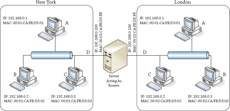
Now as you will see between the two different sites of London and New York, the IP addresses of the machines are on different subnets. So let us think for a second on how a host from the New York site would talk to or send a packet to a host located in the London site. To determine that, you need to know about network masks.
We have deliberately chosen the netsh version of the router table, because it uses the more recent CIDR format, as opposed to the older netmask format that appears in the route print output in Figure 20.5.
Wherever you work with networks, you will encounter some people who were taught the new format and some who learned the old format; therefore, it’s best to learn both, so you can be the interpreter between these two groups. The following description may not be entirely historically accurate, but it is logically accurate and will help you understand why the Internet is the way it is today.
When the Internet was young and the address space available to be assigned was plentiful, addresses were, well, not quite handed out like candy but were certainly assigned less strictly than they are today. Internet users were categorized into different classes, and along with them came different classes of address ranges to suit them.
The classes were named A through C, and they were each distinguished by the number of bits devoted to the network address and the number of bits devoted to the host address. With only 32 bits of IP address, a class A assignment would use 8 bits to signify the network address (i.e., a subnet mask of 255.0.0.0) and the remaining 24 to signify the host address, a class B assignment would use 16 bits for the network address (i.e., a subnet mask of 255.255.0.0) and 16 for the host address, and a class C assignment would use the first 24 bits for the network address (i.e., a subnet mask of 255.255.255.0) and 8 bits for the host address.
Classes are identified by reading the binary form to see how many of the most significant bits are set to 1, before reaching the first 0. Class A addresses start with 0, so the first octet is in the range 0000 0000 to 0111 1111 (or in decimal, 0 to 127). A class B address has a single 1 before the first 0, as in 1000 0000 to 1011 1111 (in decimal, 128 to 191). Class C addresses start with two 1s and then their first 0, so their range is 1100 0000 to 1101 1111 (or 192 to 223).
This all seemed very equitable, with class A users getting the ability to have nearly 224 (16,777,216) hosts. Class B users received nearly 216 (65,536) hosts, and class C users got nearly 256 hosts each.
Why “nearly”? In every network range, a number of addresses are not available to be assigned to hosts. The only absolute, carved-in-stone (or at least, written in the RFCs, which are the Internet’s equivalent of stone tablets) requirements are that in any network the top and bottom ends of the address ranges are reserved.
The top end of the address range—where all host bits are set to 1 (the all 1s address)—is reserved for directed broadcast. So, for instance, if your network was a class B assignment and had addresses starting with the sequence 192.168.something.something, the directed broadcast address would be 192.168.255.255, where the two 255 octets represent a binary sequence of 1111 1111. All 1s, see?
A packet sent to this address would reach every computer on the 192.168.something.something network. Every computer would pass that message up to its own IP layer, where something might be listening for that broadcasted traffic. (You will see this 192.168.something.something network appear in lots of documentation, and we will explain why in a few paragraphs.) Don’t try this on your production network because you can flood your network very easily!
The bottom end of the address range—where all host bits are set to 0 (the all 0s address)—is technically reserved for broadcasting. Wait, we already said that the all 1s address was reserved for broadcasting, didn’t we? Well, yes, that’s true—and you won’t find a system today that uses all 0s for broadcasting. But back in the Internet’s equivalent of the Bronze Age, Internet developments were being made by several different groups at once. Apparently the broadcast was invented by more than one company. Sun chose to broadcast at all 0s, and everyone else chose to broadcast at all 1s. Much to Sun’s surprise (because at the time, it was a major force in Internet development), everyone else won out.
But the all 0s address hasn’t become available for use because it also represents another concept, that of the “network address.” In router tables, as well as in network diagrams and other documentation, it refers to the network as a whole, so instead of talking about the 192.168.something.something network, you could now talk about the 192.168.0.0 network.
Internet addressing in IPv4 has an addressing concept—that all-all 1s and all-all 0s addresses, 255.255.255.255 and 0.0.0.0, represent something. All 0s’ address 192.168.0.0 now represents the network of machines from 192.168.0.1 to 192.168.255.254, so what would 0.0.0.0 represent? It generally represents a network of one computer—“this” computer. By extension, 255.255.255.255 represents “broadcast to every computer out there.”
When the Internet was small, these broadcast addresses were great. If you wanted to know what computers a company had connected to the Internet, all you had to do was find that their network address was 192.168.0.0, and that meant you could enumerate their network by pinging 192.168.255.255. You would get a response from every machine they had (and you still can, but be careful!). Then you could try to connect to random machines and see which ones were interesting.
Similarly, if you wanted to enumerate the entire Internet, that was no problem either—you simply used ping 255.255.255.255, and you got in return a response from every machine that existed.
Because each of these actions had its own risks—the first, a risk of disclosure, and the second a risk of flooding your own network (or someone else’s, if you could direct the responses to their directed broadcast address!)—pretty soon routers were being configured to disallow packets with these destinations from crossing them.
As a result, 192.168.255.255 could now be used only from inside the 192.168.0.0 network, so it became a directed broadcast that you could only direct at yourself, and 255.255.255.255 became a global broadcast that would only reach machines on your side of the router. Essentially, this meant that both broadcasts reached the same place—your local subnet—and since the 192.168.255.255 directed broadcast address required calculation but the 255.255.255.255 address could be hard-coded, pretty much nobody uses the directed broadcast form anymore. Unfortunately, this doesn’t mean you can get that address back and use it for a host.
The document that defines the all 0s and all 1s addresses (RFC 1122, “Requirements for Internet Hosts—Communication Layers”) also defines a specific class A address as being reserved for the purpose of loopback communication. This is the network 127.0.0.0, but out of that 16 million address range, almost nobody ever uses anything other than the single address 127.0.0.1, which is usually given the alias localhost.
A useful convention that has grown over the years is to use the first address or last address in a network as the location for the default router. Note that this is only a convention, and nothing forces you to do this (in our example, for instance, the router does not follow this convention; it is set to 192.168.0.100 for New York and 192.169.0.100 for London). However, following this convention would make it simpler for the person who replaces you to find the router. An example would be that in the 192.168.0.0 network, you’d use 192.168.0.1 as the address of the default router following the first address convention.
There’s that network again—192.168.0.0. Why do we keep using that network? Quite simply, it’s because we know we won’t get sued by the owners for accidentally directing traffic their way. How do we know this? This address is not owned by any one individual. Another RFC document (RFC 1918, “Address Allocation for Private Internets”) lays out a series of network ranges that are reserved for private use. By default, these addresses are not routed—a public router will not forward an IP packet whose destination is in these ranges:
Those of you who can do binary math in your heads, or have memorized the class ranges, will have realized that the range 172.16.0.0–172.31.255.255 is not a network range that matches a class. It is, in fact, a supernetwork, or supernet, of 16 class B address ranges between 172.16.0.0 and 172.16.255.255 and 172.31.0.0 and 172.31.255.255. The 192.168.*.* range is also a supernet of 256 class C networks.
Of course, if you’re in one of these networks, you’ll realize that your packets do make it outside the router—what you may not realize is that they do so by virtue of a NAT, which alters the source address to something that the router will be willing to pass.
Originally, NATs would assume that only a certain number of internal users would be accessing the Internet at any one time so that number of external addresses was assigned to the NAT, and each time a user’s traffic needed forwarding to the Internet, that user’s internal address was mapped to a free, publically routable external address. For some organizations, this is still the way in which internal systems become accessible to the outside Internet.
Something that was realized early on in the design of the IP class system was that even a huge multinational corporation that might want a class A address would not actually have one physical Ethernet wire to which 16 million devices were attached. So, a scheme was developed whereby a larger network could be divided into several subnetworks, or subnets.
The way to do this was to say that class distinctions were no longer so important; every host would have its own notion of how many of its address bits defined “the network” and how many of its address bits defined “me on the network.” Because this divided the binary address into two portions, not on an 8-bit octet boundary, they used a term borrowed from graphics processing and called it a mask. Specifically, this would be a netmask. You can imagine it as a sheet of paper with holes cut in it (just like a mask you might make for your kids at Halloween). The holes allow the network part of your address to show through and hide the host part, replacing those bits with 0s.
In Figure 20.9, we are looking at the effect of the netmask 255.252.0.0 on the address 192.168.143.8. The netmask is equivalent to the binary string 1111 1111 1111 1100 0000 0000 0000 0000—that’s 14 bits set to 1 and 18 bits set to 0.
Figure 20.9 Demonstrating how a netmask works
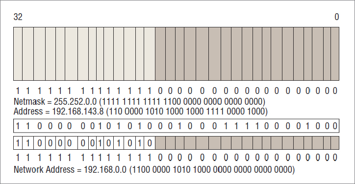
The address 192.168.143.8 is equivalent to the bits 1100 0000 1010 1000 1000 1111 0000 1000, and when you line this up underneath the netmask, you can see which bits to ignore when calculating the network address and which bits to count:
In binary mathematics, this is equivalent to defining the mask as a number that’s the same width as your address, with a 1 in every bit in the network portion, with a 0 in every bit in the host portion, and using the binary AND operation with your network address. The binary AND compares bits in the two inputs one position at a time—where the two bits are set to 1, the result will have a 1 bit; if any or both are set to 0, the result will have a 0 bit. Check our binary math, and make sure that we got it right!
As you’ve guessed from this section’s heading, there were also organizations that bought a class C and then realized that they needed to use more than 254 addresses within their organization. They could buy another class C, of course, but if they could buy a class C that was next door to their existing one, they could “supernet” the two to create a network of 29–2 addresses—510 in all. The savings in number of addresses were not the main point, however—the savings that were important in supernetting were in the sizes of the routing tables on the way to this network.
You will see these network masks in the output from route -4 print, but they are a pain to calculate and to understand what number of bits each represents. The key to remember is that there are only nine values that can appear in any octet of a netmask: 255, 254, 252, 248, 240, 224, 192, 128, 0—that’s 8, 7, 6, 5, 4, 3, 2, 1, and 0 bits, respectively. Add up the number of bits in each octet to come up with the total number of bits in a network mask to see how many bits of your host address are tied to the network.
Because a network might be subnetted at several different places, the netmask for an address depends on where you are in the network. The address 10.1.2.3, for instance, might be the third host in the network 10.1.2.0–10.1.2.255, or it might be the 66,051st host in the network 10.0.0.0–10.255.255.255.
Another casualty of subnetting and supernetting was the directed broadcast—even if the router allowed a directed broadcast to pass, how do you know how many bits to direct your broadcast at? This was yet another nail in the coffin of the directed broadcast, which now only truly exists as an annoying reason not to use the all 1s address in your network.
Many of you may have already encountered a subnet range chosen from RFC 1918 (http://tools.ietf.org/html/rfc1918) values. Every time the you connect to a wireless device in a local coffee shop, you get an address in the 10.0.0.0 class A range that is reserved for private networking. But this netmask isn’t 255.0.0.0. It’s generally 255.255.255.0—allowing for only a maximum of 253 devices (the router takes up one address!) using wireless inside the coffee shop. Wherever you may be, it’s a little optimistic to think that this limit won’t be reached!
This 10.* range is also used frequently in home networks set up by broadband installers or those who follow the instructions for the default configuration of several brands of routers. If you use 10.0.0.0–10.0.0.255 with a netmask of 255.255.255.0 in your home, technically you’re in violation of RFC 950, which says that you shouldn’t use a subnet of all 0s or all 1s. But don’t worry; the Internet police won’t come knocking on your door.
If you’re trying to take an exam based on this RFC and RFC 1122, you will want to trim off two subnets from your calculations—the all 0s subnet and the all 1s subnet.
As you can see from our assertion that the use of an all 1s or all 0s subnet address is no big deal, as well as from the widespread use of supernetting (which has no subnet part or perhaps a negative-length subnet part), it is pretty clear that the Internet’s scheme of segregating network addresses by classes was becoming completely irrelevant.
Added to this was the sheer tedium of having to calculate the network masks. Network masks were always a string of some number of bits set to 1, followed by a number of bits set to 0, with the total number of bits being 32, which is the size of an IPv4 address. To save having to write network addresses as “10.0.0.0–10.0.255.255” or “10.0.0.0 with netmask 255.255.0.0,” network administrators used a shorthand notation, writing a slash after the network number and then writing just the number of bits set to 1. So “10.0.0.0–10.0.255.255” would become “10.0.0.0/16.” The default allocation of the 10.0.0.0 address as a class A network with netmask of 255.0.0.0 would be noted by describing it as “10.0.0.0/8.”
The Internet is ruled by RFCs, as we’ve already mentioned, and this new shorthand notation was no exception. RFC 1519 defined the original solution as Classless Inter-Domain Routing (CIDR), and the name has held up.
In fact, the CIDR shortcut has been carried over into IPv6; you will see that IPv6 network prefixes throughout Windows Server 2012 R2 are specified in exactly this manner.
Remember we told you early on in this chapter IP is the only layer that is routed—that Ethernet is a broadcast system and TCP doesn’t need routing? That’s a bit of a fib, we’re afraid.
New York A’s Routing Entries
| Prefix | Gateway/Interface | Comments |
| 0.0.0.0/0 | 192.168.1.1 | The default route—this means “if you don’t find a better match below, send the packet to 192.168.0.100, or New York D.” 0.0.0.0/0 is a special value and should not be thought of as anything other than a placeholder meaning “default.” |
|
127.0.0.0/8
127.0.0.1/32
127.255.255.255/32 |
Loopback | Even the loopback address has to be routed! The first entry indicates that the entire loopback network can be reached through the loopback interface; the second entry indicates that the specific address 127.0.0.1 is on that interface, and the third entry indicates that directed broadcasts for this network can be sent there. Strictly speaking, the first entry should cover the others. |
|
192.168.1.0/24
192.168.1.2/32
192.168.1.255/32 |
Wi-Fi | This indicates that any address on New York, even the router, can be reached through the Local Area Connection interface. |
| 224.0.0.0/4 |
Loopback
Bluetooth Network Connection
Wi-Fi |
These entries indicate that multicast traffic can be sent on either of the available interfaces. |
| 255.255.255.255/32 |
Loopback
Wi-Fi
Bluetooth Network Connection |
Again, these entries indicate that broadcasts can be sent on either interface. |
route add 192.168.0.0 mask 255.255.0.0 10.0.0.1 metric 100
route add 192.168.0.0/16 10.0.0.1 metric 100
netsh interface ipv4 add route 192.168.0.0/16 "Local Area Connection" 10.0.0.1route del 192.168.0.0
netsh interface ipv4 delete route 129.0.0.0/8 "Local Area Connection"It is certainly the original design that IP should be the only point that requires routing, and it was an original goal of IP. What was the original design for TCP that it didn’t require routing, and how did that change over time?
So, just what is wrong with IP that TCP needed inventing? IP doesn’t have any concept of a connection—if we had to describe it as analogous to an existing system we’re comfortable with, it would be the postal service. Every IP packet is like a postcard that goes through the system. Much like the postal service, some IP packets get lost in transit and if you send two IP packets, one soon after the other, they may arrive in the opposite order. Unlike the postal service, some IP packets get delivered twice!
An IP packet, just like a postcard, cannot contain a simple message like “Please ignore the previous message” because it is impossible to be certain that the sender and recipient will agree on what the previous message was. With occasional packet duplication, a recipient could even believe that they are to ignore the message that told them to ignore the previous message—very confusing!
So, for some kind of communications, these restrictions needed to be overcome—and a system of connected communications needed to be developed to allow for something more akin to a telephone conversation, with a start, an ordered exchange of information, and an end. This is what TCP provides.
Strictly speaking, TCP adds to IP the following attributes:
Almost no one actually writes applications that talk directly in IP. Fewer still write applications that directly control TCP, particularly on Windows, because various security measures prevent any application other than the network stack from creating TCP packets.
Instead, applications communicate to the TCP layer by using something known as a socket. Sockets are not unique to Windows; they have been around since some of the earliest days of the Internet.
A socket, in Internet terms, consists of five things—a source address, a destination address, a source port, a destination port, and a protocol (in this case, the protocol is TCP). A pair of matching sockets (where the source address and port of one socket are the destination address and port of the other, and vice versa) constitute a TCP connection. A socket is unconnected if its destination port and address are zero, and it is unbound if its source port and address are zero. An unbound socket is also unconnected.
Although you know what an address is, we have not yet told you what a port is. Quite simply, it’s a number from 1 to 65,535, chosen to make sure that sockets can be distinguished from one another. The ports below 1024 are considered reserved, in that they are assigned to a particular protocol. For instance, ports 21 and 20 are assigned to FTP.
The life cycle of a connection starts in one of two states, depending on whether it is a server-side socket or a client-side socket. A server-side socket will start off in the LISTENING state, which requires a socket to be bound to a source address and port. The client-side socket, meanwhile, will start in the SYN-SENT state, when it starts its handshake with the server socket. This requires that the socket be bound and associated with a destination address and port. The server responds with its SYN-ACK, creating a new socket with the same source address and port as the listening socket, which it puts into the SYN-RECEIVED state. Ending the handshake, the client sends its ACK and puts its socket into the ESTABLISHED state. On the server side, when the initial ACK is received, the server too will put its socket into the ESTABLISHED state.
You can use the netstat command to get an idea of what is connecting to your machine and what state it is in. Figure 20.10 shows output from running the netstat command.
Figure 20.10 Sample netstat output
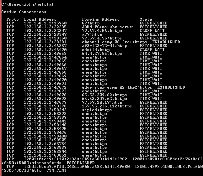
We’ll use some shorthand to describe the sockets. Each socket will be described as {source address, source port, protocol, destination address, destination port}. The web server is LISTENING at port 80, meaning it has a socket bound to source address 10.20.30.40, source port 80, protocol TCP, destination address 0.0.0.0, destination port 0—{10.20.30.40, 80, TCP, 0.0.0.0, 0}. The client creates a socket {192.168.1.2, 1025, TCP, 10.20.30.40, 80}. Huh? Where did 1025 come from? It’s the first number above 1024, so it’s the first port from the unreserved range, and it will be used as the source port for the first connection. The next connection will connect from port 8700. This is assigned randomly by applications and is very rarely in sequence. Consider it a security feature so traffic is not easily identified.
The client sends a SYN on its socket to start the handshake. When the LISTENING socket receives the SYN, the TCP layer creates a copy of the LISTENING socket and sets the destination address and port to match the incoming connection request, so it now has two sockets: {10.20.30.40, 80, TCP, 0.0.0.0, 0} in the LISTENING state and {10.20.30.40, 80, TCP, 192.168.1.2, 1025} in the SYN-RECEIVED state after the SYN-ACK is sent. This socket is paired with the client socket of {192.168.1.2, 1025, TCP, 10.20.30.40, 80} to form the connection. When the client receives the SYN-ACK and sends its ACK in response, both sockets can go to the ESTABLISHED state. A new socket, but not a new port, has been created at the server.
From now on, it is meaningless to call one socket the server and one socket the client; they are both on an equal footing. Each can send and receive data at any time. Although many protocols insist on strict synchronization between command and response, TCP is an asynchronous communications protocol, meaning that any side can send at any time.
To terminate the connection gracefully, one side of the communication (we’ll call it the closer) will send a FIN and set its socket into the FIN-WAIT-1 state to indicate that it is waiting for an acknowledgment of its FIN, as well as for the other end (we’ll call it the closee) to close the socket with a FIN. The closee can carry on sending data but will not receive more data from the closer after the FIN that it received.
At some point, usually pretty quickly after receiving the FIN, the closee will send an ACK that acknowledges the FIN. This will cause the closee to enter the CLOSE-WAIT state, indicating that it knows that it won’t receive anything more but that it’s still waiting for the application to finish sending and close. When the closer receives this ACK, it will enter the FIN-WAIT-2 state.
The closee will eventually finish sending data and will send a FIN to indicate that the application on its end is finished, too. After sending the FIN, the closee enters the LAST-ACK state (it’s waiting for an ACK—the last ACK—from the closer), and when the closer receives the FIN, it will enter the TIME_WAIT state and send an ACK to the closee.
The closee will close its socket on receiving this ACK, at which point it is free to forget all about that connection. Technically, the socket is in the CLOSED state. The poor closer, on the other hand, has to keep its socket in the TIME_WAIT state for about four minutes, before it too can move the socket to the CLOSED state and forget about it. (This is to prevent packets that are still bouncing around in the network from being responded to with RST messages.)
Fortunately, even application developers don’t need to handle this all for themselves. Wherever there is a network stack, there is an interface used for programming it. Back in the Iron Age of the Internet, there were as many different interfaces—or application programming interfaces (APIs)—as there were network stacks. There were about a dozen network stacks.
For the poor network programmers among us, that meant either we had to write a dozen different versions of our software or we had to pick one or two network stacks and hope we had backed the right horse. The “right horse” could change midstream, if you don’t mind us mixing a metaphor, whenever the next “killer app” came along and its authors chose a different network stack than the one you had chosen.
Then in 1992 or 1993, the network stack vendors realized that this was constricting their market, because no one was producing applications for Windows networking. They banded together in what they called a spirit of “coopetition” and developed, over the course of several months, a common API that they would all stand behind. They called this Windows Sockets, because it was very similar to the BSD Sockets API on Unix systems. Everyone else quickly called it Winsock, because that’s the name of the library with which you linked your network program.
It’s some coincidence (but not much) that at this time the National Center for Supercomputing Applications released a hugely popular web browser called NCSA Mosaic that was available for Windows, among other platforms.
The graphical web browser from NCSA played a huge part in popularizing the Internet (fans of the musical Avenue Q will realize immediately why), as did the arrival of America Online (AOL) and its subsequent adoption of Winsock as the chief method of connecting applications to its dial-up stack.
Of course, these days, there are no “dozen network stacks” for Windows. For most of us, there is just one, and it comes from Microsoft. But it still supports Winsock, and developers can still write networking programs that they can feel reasonably certain will run on any Windows system.
Thanks, Winsock!
So now that you know all about sockets and ports, we can explain the next big leap in technology for routing private networks to the Internet. With a plain NAT, we have shown that you could only have as many externally connected clients as you had external IP addresses—and this during a time when the number of available IP addresses is drying up.
The next bright idea, then, was to make possible the use of one external IP address for several internal IP addresses. This kind of NAT router would have to look beyond the IP layer into the TCP (or UDP) layer and use the IP address and port to map connections, rather than entire IP addresses, to external connections.
Such a router is called a network address/port translator (NAPT). Some people may also call it a port/address translator (PAT). We prefer NAPT, partly because this is what the RFCs refer to, but mostly because the “network” part of the job hasn’t been lost, so the initial doesn’t need to be tossed.
Because NAPT routers are so useful compared to NAT routers and because NAPT is a little harder to say, for the most part what you hear referred to as a NAT router is actually a NAPT router. Some enterprises still use a NAT router as an IP-level NAT router with no port translation, but that is somewhat of an oddity these days.
When a NAPT router sees a SYN crossing its bow from an internal address, it will assign an external IP address and a port (usually the same number as the internal port, but in case of conflicts, this can be assigned essentially at random) to that connection attempt. Then, whenever it sees the internal IP and port in a TCP-bearing IP packet coming from its inside edge, it will edit that packet and insert the external IP and port before forwarding the packet to the Internet. Likewise, when it sees an incoming TCP-bearing IP packet on its outside edge, it will find the matching internal IP address and port to replace that with, before forwarding the edited packet to its internal target.
For most applications, NAPT works really well. Indeed, it has an unexpected benefit to those of us who beg for security devices to “fail closed” and to “deny by default.” Every NAPT device acts as a firewall, because by default a NAPT will not know where to send any incoming packet. Rather than guessing, the NAPT will either drop the packet or respond with a failure indication, such as an RST response.
Most NAPTs allow you to configure port mappings, for instance, to tell the NAPT that “we have a web server running at 192.168.230.21, port 80,” in which case it will assign a static mapping from its external IP address, which is port 80, to its internal address 192.168.230.21, which is port 80.
You can also configure most NAPT devices to forward any unknown traffic to a particular IP address, sometimes known as the DMZ host. Try to resist the temptation to do this, because this will result in that host being bombarded with every network attack known to man. The Internet is a little hostile to those without a firewall.
For some applications, however, NAPT devices have practically killed the protocols on which they rely. There are several protocols, such as FTP (file transfer), SIP (session initiation—for phone-like communication), and H.323 (again, for voice- and videophones), that send information about IP addresses and ports in their communication with their connection partners. Even IPsec, the secured protocol for IP that allows for authentication and encryption of IP traffic, will sometimes need to quote its IP address.
For instance, an FTP client will tell the FTP server “connect back to me at my address 192.168.230.21 on port 1025,” with a command, such as PORT 192,168,230,21,4,1. The server can’t connect to that address and port because it’s a nonroutable address. This usually results in a time-out when the upcoming file transfer is attempted and makes FTP very hard to use from behind a firewall.
The developers of the NAPT specification (again, it’s in an RFC—this time RFC 3022, “Traditional IP Network Address Translator”) were aware of this kind of problem and suggested that Application Layer Gateways (ALGs) could be added to any NAPT router.
Such an ALG would inspect the contents of the TCP payloads for recognized protocols and commands, editing the TCP stream itself to change IP addresses and port numbers quoted there and opening up mappings to allow incoming connections as requested.
This works acceptably well except in the case where a protocol is unrecognized by the NAPT as belonging to a particular ALG. The cause of this can be as simple as the use of a different port or as complex as the use of encryption (IPsec, for instance, or FTP over SSL/TLS). In the former case, the NAPT doesn’t know that you’re sending FTP traffic because the server is not at port 21; in the latter case, the NAPT sees only encrypted data, which it can neither read nor modify.
Possibly the most likely use you will have for making a Windows Server 2012 R2 machine into a router is if you want to create a NAT over which you have finer control than you would get from a normal NAT device.
Installing NAT in Windows Server 2012 R2 is relatively simple, although it has many steps:
 Add Roles and Features.
Figure 20.11 Adding the server role for Remote Access
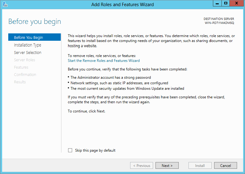
Figure 20.12 Selecting “Role-based or feature-based installation”
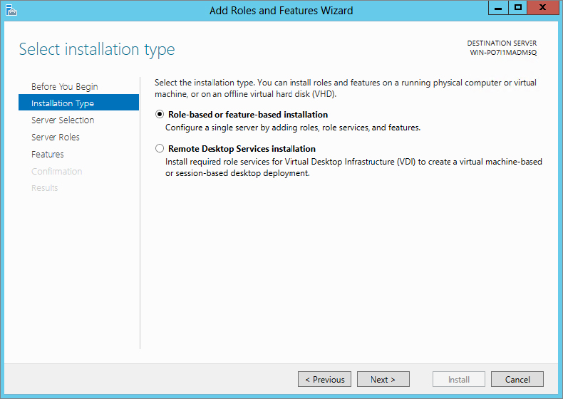
Figure 20.13 Remote Access role selection

Figure 20.14 Remote Access role additional features
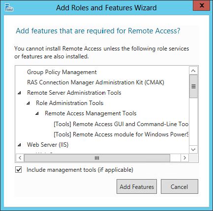
Figure 20.15 Remote Access preamble
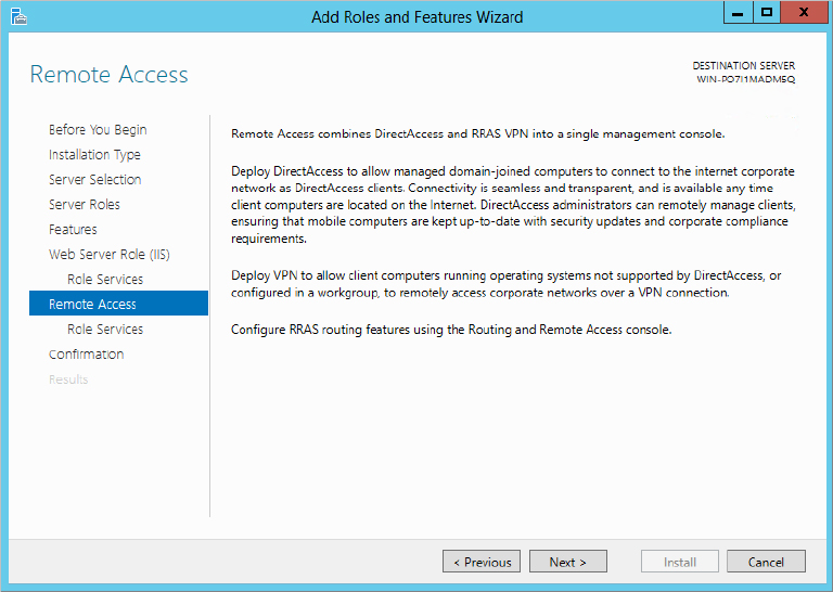
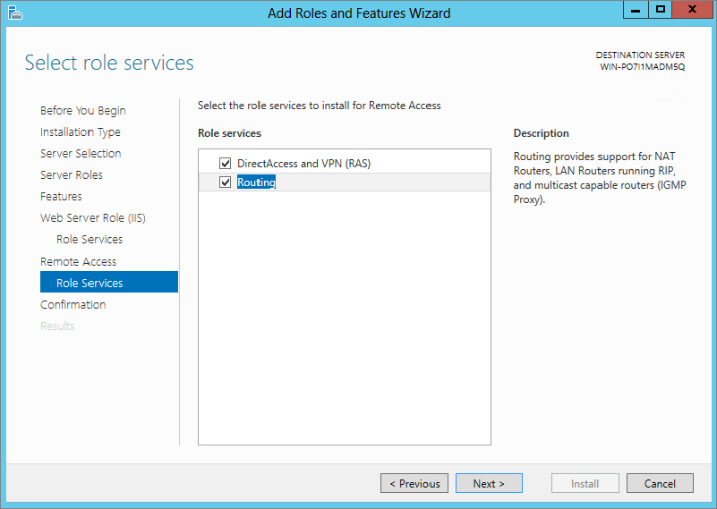
Figure 20.16 Routing selection in Remote Access Role Services screen
One of the great things about Windows Server 2012 R2 is it follows up for you when post-configuration work is required. From Server Manager you will notice on the top part of the screen a flag symbol with a yellow exclamation mark.
Figure 20.17 Post-deployment Configuration
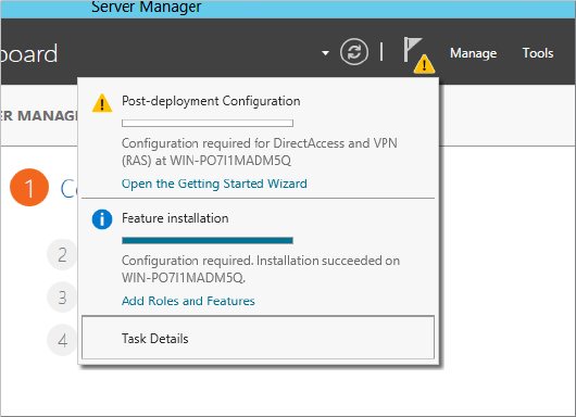
Figure 20.18 Configure Remote Access Getting Started Wizard

Figure 20.19 Launching Routing and Remote Access
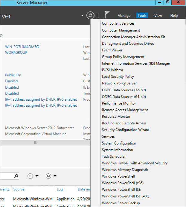
Figure 20.20 Configure and Enable Routing and Remote Access
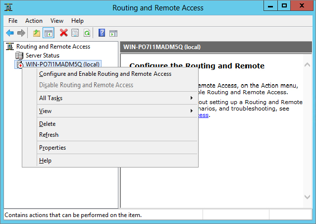
Figure 20.21 Configuration screen of the Routing and Remote Access Server Setup Wizard
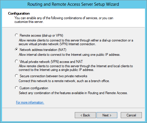
Figure 20.22 NAT Internet Connection screen—selecting the interface
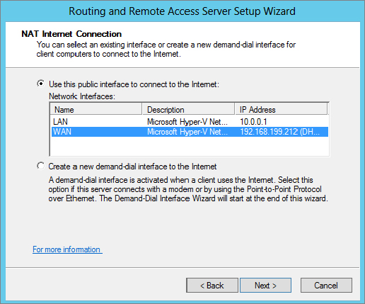
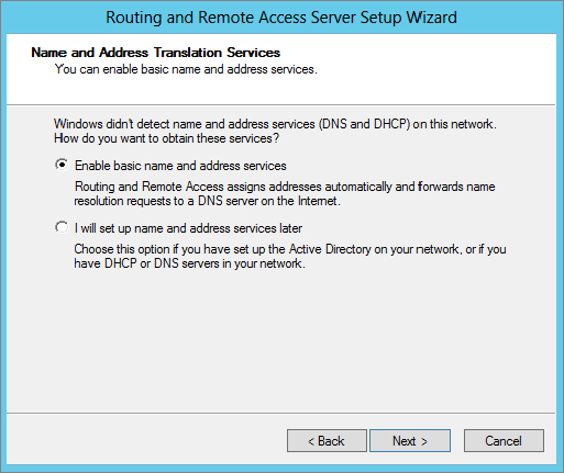
Figure 20.23 Name and Address Translation Services screen
There—you’re finished! Now, any system configured with a default gateway or static route on the same network subnet connecting to the interface you’ve defined as internal (in our example, this was the New York subnet), will be configured to connect to the public Internet.
You’ve probably guessed that, like so many other NATs, the NAT in Windows Server 2012 R2 is really a NAPT, in that it will translate and map ports as necessary. There are also some built-in ALGs to support the use of FTP and PPTP.
What is a router? A router is a multihomed machine (that is, one with more than one network interface) that has been set up to forward packets received from one network to another network.
The computer that sits between the New York and London networks, which we will call the Gateway computer, is well placed to be a router—it is multihomed, and each interface is on a different network. But is it a router yet? Not until it has been configured to forward.
By default, Windows Server 2012 R2 computers are not configured to forward. To cause a Windows Server 2012 R2 computer to forward IPv4 packets, you need to edit a registry setting. The setting is HKEY_LOCAL_MACHINE\SYSTEM\CurrentControlSet\Services\Tcpip\Parameters\IPEnableRouter; it should already exist as a dword value set to 0, so set it to 1 in order to enable IP routing, and then restart the computer.
That’s all you need to do to create a router between two local subnets. This computer will now automatically forward packets received on one interface to the interface corresponding with the network containing the destination address of the packets. Again, you can use the route add (or netsh, if you like typing) command to add any routes that are not already present in the router.
Network tunneling is a form of routing in which network traffic is encapsulated or transformed in some way by a tunnel endpoint so that it can reach another tunnel endpoint, at which point it is either de-encapsulated or transformed back.
In a way, NAT is a form of tunneling in which the transformation is to change the source and/or destination IP address and port along its travels. As with other tunneling methods, several NATs may be between the start of the packet’s travel and its end.
The last netsh tunnel you’ll visit is a very useful one, called portproxy. You can use it to cheat port restrictions by forwarding a “safe” port such as 80 (for the Web, using HTTP) to an “unsafe” port such as 119 (Network News Transfer Protocol—often blocked by enterprises to limit employees’ access to this information source).
At the other end, forwarding port 119 to port 80, you begin by encapsulating the NNTP traffic from your newsreader into a connection that seems to the firewall to be a connection to a web server.
Assuming that your home computer is at address 10.20.30.40 and the news server you want to reach but can’t is msnews.microsoft.com, these are the commands to use:
[At the work computer] netsh interface portproxy add v4tov4 119 10.20.30.40 80
[At the home computer] netsh interface portproxy add v4tov4 80 msnews.microsoft.com 119
Connecting to systems at home using this method is probably going to get you into trouble, but there may be some work uses you can use this method for. Note that portproxy does not offer any kind of authentication, and it does not provide any encryption to protect your data in transit. You may find that a virtual private network (VPN) offers you more of what you need in this direction. Read Chapter 21 to find out how to configure Windows Server 2012 R2 as your VPN endpoint.
netsh interface ipv6 add v6v4tunnel IP6Tunnel myIPv4Address 72.52.104.74
netsh interface ipv6 add address IP6Tunnel 2001:db8:1234:567:2
netsh interface ipv6 add route ::/0 IP6Tunnel 2001:db8:1234:567:1 publish=yes
netsh interface ipv6 set interface IP6Tunnel forwarding=enable
netsh interface ipv6 add route 2001:db8:fedc:ba98::/64 "Local Area Connection" publish=yes
netsh interface ipv6 set interface "Local Area Connection" forwarding=enable advertising=enableAnother use for portproxy is to “IPv6-enable” an application that is able to use IPv4 traffic only. Again, picking on NNTP as the protocol in question, if you have an IPv4-only newsreader and an IPv6-only news server, you can connect the two with a portproxy command like this:
netsh interface portproxy add v4tov6 119 news6server.example.com 119Then simply set your newsreader to point to localhost:119, and it will connect through the proxy to the IPv6 news server!
You will never need this section because with the information we have given you in this chapter you should understand routing in the context of a Windows Server 2012 R2 server. Oh, maybe that’s a bit of an exaggeration—some basic troubleshooting will allow you to determine which machine beyond your control is administered by someone without your knowledge and is causing the problem you are experiencing.
You can use many tools to debug the state of a network. Which you use, and when, will depend on the problem that you are trying to fix. The first tool, as ever, should be the one you actually plan to use. Let’s say you’re trying to make an FTP connection—first, read the errors that the FTP client is giving you.
If the FTP client says “Connection refused,” then the client has received a TCP RST ostensibly from the IP address you tried to reach. This could be a sign of a firewall between you and the server, or the server application itself might not be running.
If the FTP client says “Timed out,” then the client has received nothing in response to multiple requests to connect. This means either a “stealth” firewall is in between the client and the server or the server computer isn’t reachable right now, either because there is no network route to it or because the computer is not currently running.
ping is the classic tool that many of us have used for decades. Its design has varied a little, but the basic principle is to send a packet to a remote machine that the remote machine is supposed to reply to and then wait for the reply and indicate whether it is successful. Windows Server 2012 R2 still uses the “classic” ping method of sending an ICMP echo request to the remote machine (with extra data consisting of “abcdefghijklmnopqrstuvwabcdefghi”) and waiting for the ICMP echo reply to come back.
Thus, it is important to remember that ping tests only ICMP echo connectivity; it does not test the TCP connection to a server port. Only a TCP connection to the server port will do that (which is why we suggested earlier that your first debugging tool is the application you’re trying to debug!).
Many firewalls block the ICMP echo service, so, as you can demonstrate by first pinging and then connecting with a web browser to www.microsoft.com, a failed ping does not necessarily mean a failed connection will result.
A successful ping, however, indicates that a machine somewhere is responding to your echo requests. You can also use the output from the ping command to ensure that you are resolving the name to the right IP address. The NsLookup tool allows you to query a DNS server, which makes it only a good tool for debugging the DNS server—to find out what the DNS client is going to do with a name, ping is as good as any other tool.
ping has a bewildering array of arguments. The most useful are the following:
For most troubleshooting, however, all the default parameters will generally be sufficient, and you can use ping server.example.com to give a rough-and-ready estimation of whether the server is resolvable and reachable.
tracert, as Microsoft chose to abbreviate traceroute (does anyone still remember the days when eight-dot-three filenames were all we had?), is a tool whose purpose is to detail the route to a destination. As with ping, tracert is not necessarily an absolute indication that a TCP connection to a remote host will or will not work. But it’s generally going to give you information that you can use.
tracert acts in a very similar way to ping, in that it sends an ICMP echo request and waits for an ICMP echo reply. How it differs is that tracert sets the TTL (hop count) on outgoing echo requests. The first three packets are sent with a hop count of 1, the next three are sent with a hop count of 2, and so on, up to a number you can specify (but that defaults to 30).
Since routers decrease the hop count on packets as they pass through, the first three packets will encounter an error at the first router on the way to the destination computer. Fortunately for tracert, this router reports that it discarded the packet, and the tracert program uses this information to display the address of the first router. Similarly, the second three packets will show where the second router is, and so on.
Some routers are not configured to respond with this information or are so busy that they don’t have time to do so. These routers will be seen as a “time-out” in the tracert output. This may happen at one or two hops along a route. When you see several time-outs in a row, it usually indicates that the last router before the string of time-outs is unable to forward packets toward your destination or that your destination is not responding.
As you can see from the tracert output in Figure 20.24, the host for www.microsoft.com in this part of the world is lb1.www.ms.akadns.net. This may be different if you reproduce this test. We know already, from trying to ping this host, that it does not answer to ICMP echo requests, and for that reason, packets with hop counts of 14 or more are not replied to, either with echo replies or with errors.
Figure 20.24 Tracing the route to Microsoft’s website
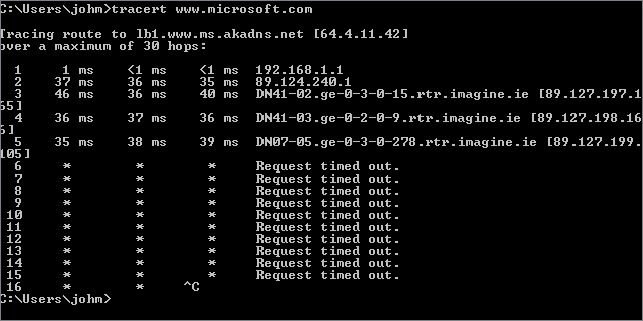
However, this tracert output does give you a fairly good idea of the route toward Microsoft’s website. Don’t be put off by the * responses, it is quite common to block ICMP-based traffic to prevent probing.
Again, tracert has the parameters -4 and -6, which you can use to force the trace to go over IPv4 or IPv6, respectively.
ipconfig will show information about the configuration of some or all of your network cards. ipconfig /all shows very detailed information, and ipconfig on its own shows a limited subset of that information. The best use of ipconfig is to ensure that your configuration matches what it is supposed to be, at least according to the network diagrams you’re trying to match reality to.
Note that a number of virtual interfaces will show up in this listing. For instance, if you have enabled a VPN server or RRAS as a dial-up access point, an interface will be assigned for those connections to use.
For network interfaces that assign addresses through DHCP, it can be useful to run ipconfig /renew or ipconfig /release followed by ipconfig /renew. It may be just as quick, and require fewer privileges, to simply unplug and replug the associated network cable—that, too, causes a release and renew against the DHCP server.
We have talked about the routing table in Windows Server 2012 R2 in this chapter, and you should find that analyzing the routing table as if you were the router can be constructive in tracing where a fault lies. If your routing table is very large and is not easily understood, that can be a fault in itself, in that no one thoroughly understands even a small section of the network enough to say that it is working as designed.
In addition to the routing table, using arp -a or netsh interface ipv6 show neighbors will let you know who this computer has recently been talking to on the local area link. If there are no entries in the table, except for those used by multicast addresses and loopback adapters, this indicates that the computer is probably not able to reach any of its neighbors on the local network link. This is often a sign of a faulty cable or switch port, and swapping out the cable or plugging it into a different port at the switch is a good option to try.
A lack of neighbors may also indicate an inability to negotiate network speeds with the switch. A recent case we worked on involved an old but generally serviceable 10/100 Mbps switch and a new computer with a Gigabit Ethernet card. The Ethernet card always negotiated down to 10 Mbps, and when we forced it to 100 Mbps, it would not see any other systems on the network—its ARP table would empty out. Replacing the switch with a new switch fixed that issue.
Previously exclusively reserved for Windows Server administrators who knew where it was, and with its greatest features available only to users of Microsoft’s System Management Server, Network Monitor is now a free commodity, available from the Microsoft download site. The current version, Network Monitor 3.3, is available from:
http://www.microsoft.com/en-ie/download/details.aspx?id=4865
Or you can simply connect to
http://www.microsoft.com/downloads
and search for Network Monitor.
It has gone through a significant rewrite, and if you have any developers in your enterprise, you can entice them to write protocol-analysis scripts in Network Monitor’s own C/JScript-like language. Or you can use the scripts already there to analyze what traffic is present on your network. Additionally ensure you download the parsers from:
http://nmparsers.codeplex.com/
These give additional decoding abilities for protocols so you can better understand the messages on-screen.
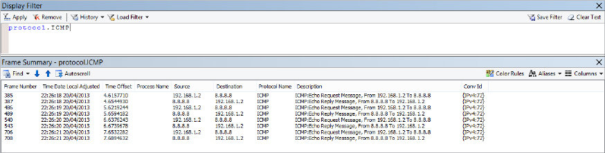
As you can see from Figure 20.25, this capture, plus a simple filter protocol.ICMP, allows us to see all the traffic generated by our earlier use of the ping command.
Figure 20.25 Viewing a ping capture using Network Monitor 3.4
If you want to capture data from only one card using Network Monitor, how do you decide which one to use? In most situations, this is relatively obvious because there is only one network card in most systems, and therefore there is no choice to make. However, one wrinkle comes out of the changes made between IPv4 and IPv6, and that is the topic of weak sends and weak receives:
IPv4 for decades has confused network administrators with its behavior. Weak sends are enabled by default in IPv4 interfaces, which means that the interface that is chosen for sending an IP packet depends on the destination IP address, not the source IP address. The interface that is chosen is the one that is closest to the next-hop address in the route toward the destination.
That’s not the case in Windows Server 2012 R2 and Windows 2008 R2, however. In Windows Vista and Windows Server 2008, Microsoft took the bold step of requiring that IP packets go out on the interface that matches their source address and, similarly, that IP packets will be discarded if their destination address does not match that of the interface on which they were received.
IPv6, by comparison, does not enable weak sends by default, so the packet will always be sent to the interface whose IP address matches the source IP address of the outgoing packet. No change there in Windows Server 2008.
The change, however, is that you can change this behavior. As with all new network configuration commands, you can achieve this through netsh:
netsh interface ipv4 set interface <NameOrIndex> weakhostsend=enabled
netsh interface ipv4 set interface <NameOrIndex> weakhostreceive=enabled
netsh interface ipv6 set interface <NameOrIndex> weakhostsend=enabled
netsh interface ipv6 set interface <NameOrIndex> weakhostreceive=enabled
Of course, you can set any of these values back to disabled, as the default, if you prefer that behavior.
Disabling weak host receives is a security feature for a multihomed computer, in that packets will be discarded if they are not received on the anticipated interface, but this may discard valid traffic that really should reach your computer, if the routing and the cabling send it to the wrong interface. If that is the case, then your network design needs revisiting. A local link, or subnet, should not find itself split across two network cards in a single computer.
In this chapter, we have given you a taste of some of the routing capabilities of Windows Server 2012 R2. You will shortly encounter a big routing ability in Chapter 21’s description of virtual private networks.