The R&S overlay is the R&S plan in graphic form. The purpose of the R&S overlay is to show the assets and the key staff officers exactly where the R&S assets are operating. You will extract most of the overlay’s graphics and symbols from FM 101-5-1. Additionally, due to the various R&S operational techniques, you will need to construct some “homemade” graphics and explain them in the legend.
There are two parts to the R&S overlay. The first part is the graphic display of deployed or planned deployment of R&S assets. The second part is the marginal data consisting of the legend, administrative data, specific instructions to each asset, and the distribution list.
The marginal information found on the overlay consists of the standard wording found on all overlays. The administrative data is comprised of the following:
Another portion of the administrative data is the legend. The legend contains any nonstandard FM 101-5-1 graphics used. It also contains detailed written instructions to each R&S asset. These detailed instructions should focus on:
Initially, the locations for assets are areas in which you recommend they deploy. After the assets have gone to these areas (NAI), they report to you or the S3 the actual locations in which they can conduct their missions. You or the S3 updates the graphics to show actual locations.
Control measures are as follows:
All of these control measures, except R&S limit of responsibility, are found in FM 101-5-1. The R&S limit of responsibility comes down from higher headquarters along with other R&S guidance. This limit is a control measure that informs subordinate units of the limits of their R&S operations. It can be represented by a dashed line (- - - - ).
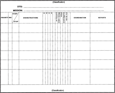
Remember, it is important to include detailed instructions for each R&S asset on the overlay. This method is known as the overlay method for distributing written instructions. Another method is known as the matrix method. The R&S tasking matrix is the matrix used for this method. (See Appendix A.) Figure 6-1 shows an R&S tasking matrix.
Figure 6-2 is an example of the R&S plan graphically portrayed on an overlay with detailed instructions to each asset written on the bottom of the overlay. Attach the R&S tasking matrix to the bottom of the R&S overlay. The matrix provides the following information:
We have discussed two ways to distribute instructions; however, the method is not important. What is important is for assets to receive clear, specific instructions.
Disseminating the R&S plan to all the assets can be a problem. When the R&S plan reaches the dissemination phase, the assets are usually scattered great distances over the battlefield. In some instances the R&S plan is disseminated by courier. To ensure all assets receive their copy, write each asset’s title directly on the distribution list, plan, or
Figure 6-1. R&S tasking matrix.
Figure 6-2. R&S overlay with instructions on acetate.
overlay. Exchanging brigade or battalion R&S plans with adjacent units ensures proper coordination, minimizes the risk of shooting friendly soldiers, and cuts out unnecessary redundancy.
Chapter 5 provides additional methods for disseminating R&S requirements. See FM 34-80, Appendix E, for another sample R&S overlay.