Chapter 4
Beginning Polygonal Modeling
Simple objects call for simple models, and complicated objects call for a complex arrangement of simple models. Like a sculptor, you must analyze the object and deconstruct its design to learn how to create it.
The Autodesk® Maya® software primarily uses two types of modeling: polygons and NURBS. Both require a process that begins with deciding how best to achieve your design, although it’s common to mix modeling methods in a scene.
To help you decide where to begin, this chapter starts with an overview of modeling, briefly describing the two popular methods and how they differ. You’ll also learn about primitives. The second part of the chapter takes a detailed look at modeling with polygons. (The next two chapters cover the process of modeling with polygons and NURBS surfaces and how to bring them together in one model.)
- Learning Outcomes: In this chapter, you will be able to
- Decide how to plan your model
- Edit polygon geometry in traditional Maya as well as Modeling Toolkit workflows
- Navigate the Modeling Toolkit interface
- Work with the Modeling Toolkit selection workflow
- Extrude, bevel, and wedge polygons
- Use edge loops to create detail
- Create curves and use the Revolve function to convert them to polygon meshes
- Adjust grouping and hierarchies in a complex model
Planning Your Model
When you dissect the components of an object into primitive shapes, you can then translate and re-create the object in 3D terms.
First, you should take reference pictures from many angles, get dimensions, and even write down a description of the object. The more perspectives from which you see your subject, the better you’ll understand and be able to interpret your model.
You must also decide the purpose for your model and determine the level of detail at which it will be seen in your CG scene. Consider the two scenes in Figure 4-1. If you need to create a park bench for a far shot (left), it will be a waste of time and effort to model all the details such as the grooves in the armrest. However, if your bench is shown in a close-up (the images on the right), you’ll need those details.
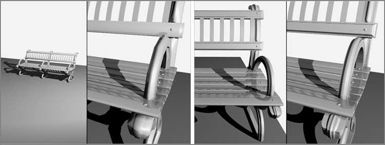
Figure 4-1: The level of detail you need to include in a model depends on how it will be seen in the animation.
If you aren’t certain how much detail you’ll need, it’s better to create a higher level of detail rather than skimping. You can more easily pare down detail than create it later.
Keep in mind that you can also add detail to the look of your model in the texturing phase of production, as you’ll see with the decorative box later in the book. (Chapter 7, “Autodesk® Maya® Shading and Texturing,” covers texturing.)
Choosing a Method
Polygon modeling involves tearing and extruding from larger pieces to form a desired shape. This method is typically preferred by most digital artists in the field.
NURBS modeling is great for organic shapes because smooth lines, or curves, are the basis of all NURBS surfaces. However, NURBS tends to be more difficult in comparison since it’s more difficult to create a complete model without several surfaces that must be perfectly stitched together, a process not covered by this book. Subdivision surfaces combine the best of both worlds but are not a popular workflow and is largely hidden in the interface now; therefore, it will not be covered in this book. Basic NURBS modeling is covered in the next chapter.
An Overview of Polygons
Polygons consist of faces. A single polygon face is a flat surface made when three or more points called vertices are connected. The position of each vertex defines the shape and size of the face, usually a triangle. The line that connects one vertex to another is called an edge. Some polygonal faces have four vertices instead of three, creating a square face called a quad.
Polygonal faces are attached along their polygonal edges to make up a more complex surface that constitutes your model (as shown with the polygonal sphere in Figure 4-2). A camping tent is a perfect example. The intersections of the poles are the faces’ vertices. The poles are the edges of the faces, and the cloth draped over the tent’s frame is the resultant surface.
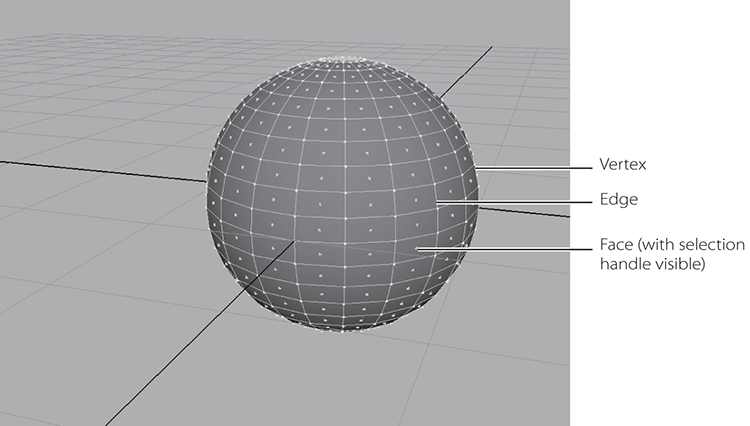
Figure 4-2: A polygonal sphere and its components
Polygon models are the simplest for a computer to render. They’re used for gaming applications, which need to render the models as the game is running. Gaming artists create models with a small number of polygons, called low-count poly models, which a PC or game console can render in real time. Higher-resolution polygon models are frequently used in television and film work.
Using Primitives
Primitives are the simplest objects you can generate in Maya (or in any 3D application). They are simple geometric shapes—polygons or NURBS. Typically, primitives are used to sculpt models because you can define the level of detail of the primitive’s surface; they offer great sculpting versatility through vertex manipulation.
To get a better sense of how to begin a modeling assignment, you may find it helpful to analyze your modeling subjects into forms and shapes that fit in with Maya primitives. Figure 4-3 shows all of the primitives in Maya, including NURBS, polygons, and volume primitives. Quite different from geometry primitives, volume primitives are used for lighting and atmosphere effects, such as fog or haze, and don’t play a part in modeling.
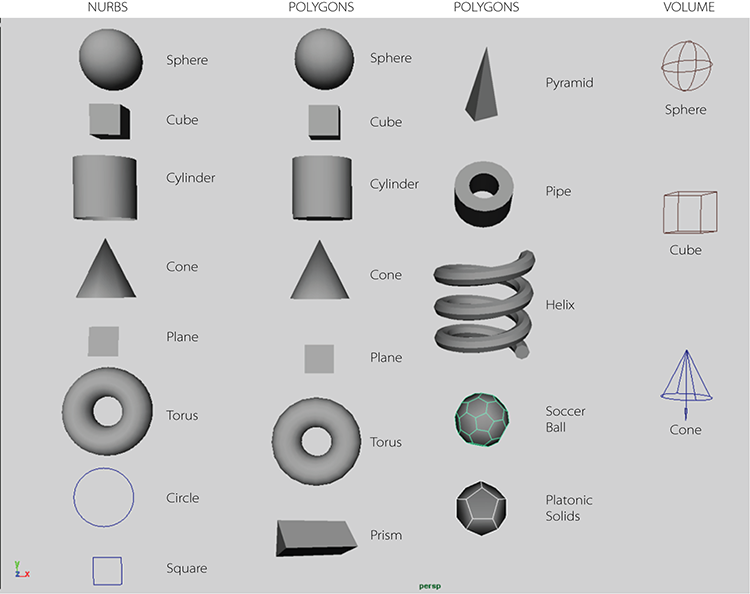
Figure 4-3: The Maya primitives
Polygon Basics
Polygon modeling is popular because its resulting models are usually one piece of geometry with many facets. You can, therefore, deform polygon models without fear of patches coming apart, as can happen with NURBS. Polygons, however, have a finite detail limitation and can look jagged up close or when scaled up. One solution to this problem in the Maya software is the Smooth tool.
A popular method of polygonal modeling, sometimes called box modeling, involves creating a base object, such as a simple cube, and then pulling and pushing faces to draw angles to create more faces. Whereas you typically need to create curves to start NURBS, you usually create complex polygons from basic-shaped polygons such as primitives.
A second method for creating poly surfaces uses the same curves that NURBS surfaces use or even converts a completed NURBS surface model to polygons. A third method is to create poly surfaces directly with the Polygon tool, which allows you to outline the shape of each face.
Creating Polygonal Primitives
With a poly mesh, detail is defined by subdivisions, which are the number of rows and columns of poly faces that run up, down, and across. The more subdivisions, the greater definition and detail the mesh is capable of.
Choosing Create ⇒ Polygon Primitives gives you access to the poly version of most of the NURBS primitives. Opening the option box for any of them gives you access to their creation options. To see an example, choose Create ⇒ Polygon Primitives ⇒ Sphere and open the option box.
To get started, first make sure History is turned on ( ) in the status bar
along the top of the UI), or there will be no creation node; then, click Create to
make the poly sphere. Open the Attribute Editor and switch to its creation node,
called polySphere1. In the creation node polySphere1 you’ll find the Subdivisions
Axis and Subdivisions Height sliders (in the option box, these are called Axis and
Height Divisions), which you can use to change the surface detail retroactively.
) in the status bar
along the top of the UI), or there will be no creation node; then, click Create to
make the poly sphere. Open the Attribute Editor and switch to its creation node,
called polySphere1. In the creation node polySphere1 you’ll find the Subdivisions
Axis and Subdivisions Height sliders (in the option box, these are called Axis and
Height Divisions), which you can use to change the surface detail retroactively.
The Polygon Tool
You use the Polygon tool to create a single polygon face by laying down its vertices (switch to the Polygons menu set and then choose Mesh Tools ⇒ EDIT ⇒ Create Polygon Tool, in the EDIT section of the menu). When you select this tool, you can draw a polygon face in any shape by clicking to place each point or vertex. Aside from creating a polygon primitive by choosing Create ⇒ Polygon Primitives, this is the simplest way to create a polygon shape. Figure 4-4 shows some simple and complex single faces you can create with the Polygon tool.
After you’ve laid down all your vertices, press Enter to create the poly face and exit the tool. For complex shapes, you may want to create more than just the single face so that you can manipulate the shape. For example, you may want to fold it.
- Try This The poly shown in Figure
4-5 was created with the Polygon tool and has only one face. Therefore,
adjusting or deforming the surface is impossible. To fold this object, you need
more faces and the edges between them. Make your own intricate poly shape with
the Polygon tool by clicking vertices down in the different views to get
vertices in all three axes.
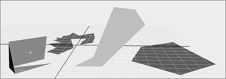
Figure 4-4: Polygon faces created with the Polygon tool
With the surface selected, choose Mesh ⇒ SHAPE ⇒ Triangulate. The surface has more faces and edges and is easier to edit, but it’s still simple to create because you start with a single face. If you need a uniquely shaped poly, start with this tool and then triangulate your surface into several faces, as shown in Figure 4-6.
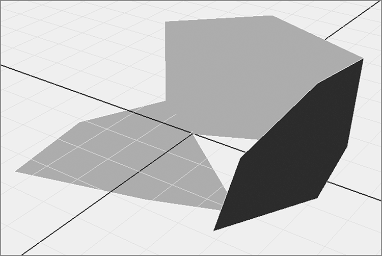
Figure 4-5: A single-faced polygon with a complex shape
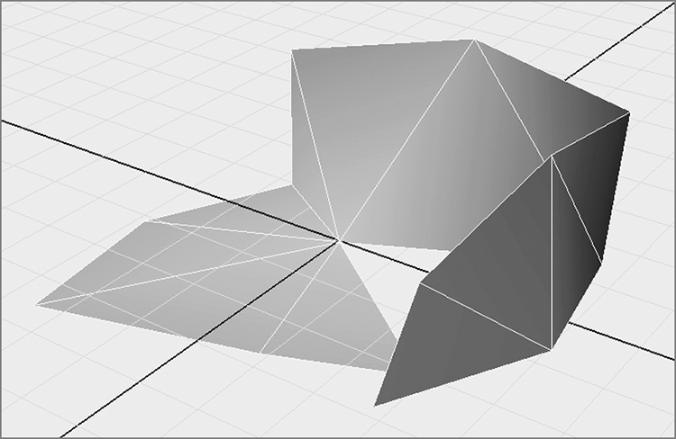
Figure 4-6: Complex shapes are better with more faces.
Poly Editing Tools
Here’s a brief preview of what to expect in the world of poly editing. You should experiment with each tool on a primitive sphere as it’s introduced, so saddle up to your Maya window and try each tool as you read along.
Later in this chapter, you’ll deploy these new skills. In Chapter 6, “Practical Experience,” you’ll create a cute toy airplane to exercise your modeling skills. For most of the work in this chapter, you’ll use the Polygons menu. Open the Edit Mesh menu, tear it off, and place it somewhere on your screen so you can get a good look at the tools and functions, which are separated into sections according to function type. For example, tools that work on vertices are found under the Edit Mesh menu’s VERTEX section. It’s important to note these sections, as some tools have the same name and may be repeated more than once in the menu, but function differently if applied to vertices, faces, or edges.
Modeling Toolkit
Modeling Toolkit integrates component-level selection and editing tools (such as selecting vertices, edges, and faces, and extruding them, for example) for a more streamlined modeling workflow. Modeling Toolkit can make tedious modeling chores much easier, especially for advanced modeling techniques. I will be covering some of the Modeling Toolkit workflow and how it’s integrated into Maya 2015 alongside Maya traditional workflows to give you a comparison and allow you to decide which workflow suits you. You’ll take a look at Modeling Toolkit and its interface later in the chapter.
The Poly Extrusion Tools
The most commonly used poly editing tools have to do with extrusion. You can use Extrude to pull out a face, edge, or vertex of a polygon surface to create additions to that surface. You access the tool in the Edit Mesh menu under the respective section (FACE, EDGE, or VERTEX) ⇒ Extrude. Maya distinguishes between edge, face, or vertex extrusion based on which of those components you’ve selected and under which menu section you select the Extrude command. Follow these steps:
- Select a face or multiple faces of a polygon and choose Edit Mesh ⇒ FACE ⇒ Extrude (under the FACE section
of the menu). The regular manipulator changes to a special manipulator, as shown
in the left image in Figure 4-7.
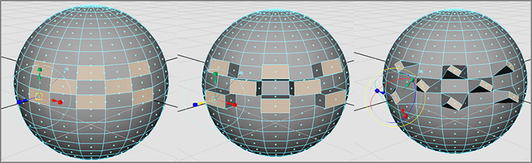
Figure 4-7: Extruding several faces at once on a sphere. The left image shows the selected faces, the middle image shows those faces extruded, and the right image shows those faces extruded with a rotation and smaller scale.
- Grab the Z-axis move handle (the blue arrow) and drag it away from the sphere, as shown in the center of Figure 4-7.
- Use the scale handles (the boxes) to scale the faces of the extrusion. The cyan circle rotates the face. The image at the right in Figure 4-7 shows the faces extruded, rotated, and scaled.
- Choose the Extrude command again without deselecting the faces, and you extrude even more, keeping the original extrusion shape and building on top of that.
- Select the edges of the poly surface instead of the faces and choose Edit Mesh ⇒ EDGE ⇒ Extrude (from the EDGE section this time) to extrude flat surfaces from the edges selected. The special manipulator works the same way as Extrude does for poly faces.
You can also use the direction and shape of a curve to extrude faces. Create a curve
in the shape you want your extrusion to take, select the curve, Shift+select the
faces, and choose Extrude  . Taper
decreases or increases the size of the face as it extrudes. Twist rotates the face
as it extrudes, and Divisions increases the smoothness of the resulting extrusion.
Choose Selected for the Curve setting. When you have your settings for those
attributes, click the Extrude button (see Figure 4-8).
. Taper
decreases or increases the size of the face as it extrudes. Twist rotates the face
as it extrudes, and Divisions increases the smoothness of the resulting extrusion.
Choose Selected for the Curve setting. When you have your settings for those
attributes, click the Extrude button (see Figure 4-8).
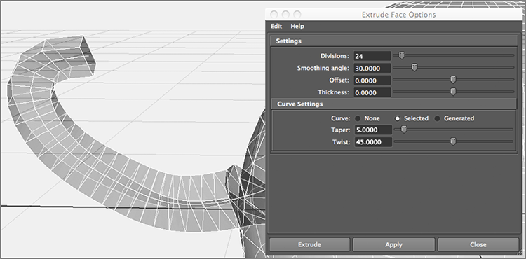
Figure 4-8: Extruding a face along a path curve
Although it seems to be strange behavior, the Twist and Taper values are taken into account in the extrusion. You can edit these values when you uncheck Selected, or you can reselect this option after you enter values for Twist and Taper. If your faces aren’t extruding to the shape of the curve, increase the number of divisions.
Modeling Toolkit and Extrusions
Modeling Toolkit makes selecting and editing polygonal components more streamlined, accelerating some workflows by incorporating tools into one place for ease of access as well as by reducing how often you have to exit one tool or mode and enter another one. Since a lot of what Modeling Toolkit does centers around component selections, let’s start there first.
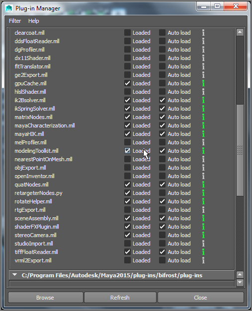
Figure 4-9: Loading the Modeling Toolkit plug-in, if needed
Modeling Toolkit Interface
By default, the Modeling Toolkit plug-in should be enabled, which places the Modeling Toolkit menu on the main menu bar. If you don’t see Modeling Toolkit, simply choose Window ⇒ Setting/Preferences ⇒ Plug-In Manager. About halfway down the list, you should see ModelingToolkit.dll (or ModelingToolkit.bundle on a Mac). Check Loaded and Auto Load, as shown in Figure 4-9.
Modeling Toolkit also places an icon on your status bar, next to the XYZ input fields, shown next to the cursor and already turned on in Figure 4-10. When the Modeling Toolkit icon is turned on, Modeling Toolkit is automatically invoked whenever you enter component selection mode. Click the icon to turn Modeling Toolkit on if it isn’t already.

Figure 4-10: The Modeling Toolkit icon button
In addition, Modeling Toolkit places a tab in the Channel Box, called Modeling Toolkit, to make displaying its tool set easier, as shown in Figure 4-11. You will notice toward the top of the Modeling Toolkit panel four icons for selecting, moving, rotating, and scaling. These operate in the same way as transformation tools; however, they enable the Modeling Toolkit functionality. You’ll see this in action throughout the book and introduced next.
Modeling Toolkit Extrusion
Now that you have a little background on how Modeling Toolkit integrates with Maya 2015, let’s use it in comparison to the Maya Extrude tool you just used on a sphere.
- Make sure the Modeling Toolkit icon (
 ) in the status bar
is active to see the Modeling Toolkit tab alongside the Attribute Editor and
Channel Box/Layer Editor tabs. Then make sure the Modeling Toolkit button in the
upper-right corner of the Modeling Toolkit is activated (
) in the status bar
is active to see the Modeling Toolkit tab alongside the Attribute Editor and
Channel Box/Layer Editor tabs. Then make sure the Modeling Toolkit button in the
upper-right corner of the Modeling Toolkit is activated ( ) so that it is in
blue.
) so that it is in
blue. - Create a polygon sphere and press 5 for Shaded mode.
- Right-click the sphere in your scene and select Face from the marking
menu for face selection mode. This is the easiest way to select components in
Maya, which also works the same while using Modeling Toolkit.
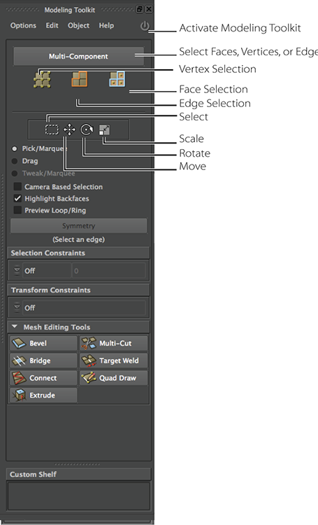
Figure 4-11: The Modeling Toolkit panel
- Your faces are now highlighting differently than they do in Maya, as you saw when modeling the decorative box in Chapter 3, “The Autodesk® Maya® 2015 Interface.” Now Modeling Toolkit selection turns the face dark red with a bold red highlight, instead of amber shading. Click a face to select it, or hold down Shift to select multiple faces. As soon as you click to select, the selected faces turn into the familiar Maya amber coloring while in Shaded mode. Select two faces side-by-side on the sphere.
- In the Modeling Toolkit panel, click Extrude under the Mesh Editing
Tools heading, as shown in Figure
4-12. The options appear below the button.
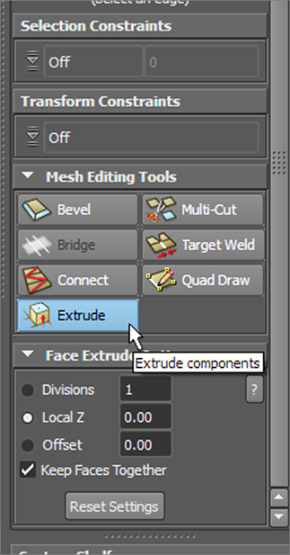
Figure 4-12: Click Extrude in the Modeling Toolkit panel.
- In the view panel, you’ll see a yellow readout telling you the axis you will be extruding in, and your cursor will change to a double-headed horizontal arrow. Click and drag left or right to set the amount of extrusion (Figure 4-13).
- In the Modeling Toolkit panel, click the Divisions button and set the
number to 3. This will give you multiple sections
along your extrusion. You can also click and drag in the view panel to set the
Divisions number interactively.

Figure 4-13: Click and drag to set the extrusion amount.
- Click the Offset button and click and drag in the viewport to make the extruded faces bigger or smaller. You may also enter a value in the Modeling Toolkit panel for Offset. Figure 4-14 shows an extrusion of 0.29 with a Divisions of 3 and an Offset of 0.04.
- Finally, click the Keep Faces Together check box on and off in the Modeling Toolkit panel to see how the extrusion changes. Figure 4-15 shows the same extrusion as Figure 4-14, but with Keep Faces Together turned off. Whatever options you set will be used the next time you extrude in Modeling Toolkit. Simply turn off the Extrude button to exit the tool and commit the changes.
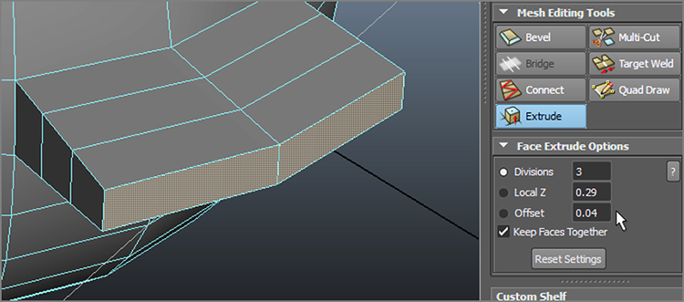
Figure 4-14: Modeling Toolkit extrusion in action
All of these extrusion options and settings are available in the Maya Extrude tool but are a little more streamlined in the Modeling Toolkit workflow. Experiment to see how you like to work. You will be using a combination of traditional Maya and Modeling Toolkit workflows throughout the chapter and other parts of the book.
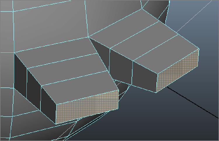
Figure 4-15: Keep Faces Together is turned off.
The Wedge Tool
Similar to extruding faces, Wedge pulls out a poly face, but it does so in an arc
instead of a straight line. For this tool, you need to select a face and an edge of
the selected face for the pivot point of the corner. Here’s how to do this. First
deactivate Modeling Toolkit by clicking the power icon () to turn off the blue
light.
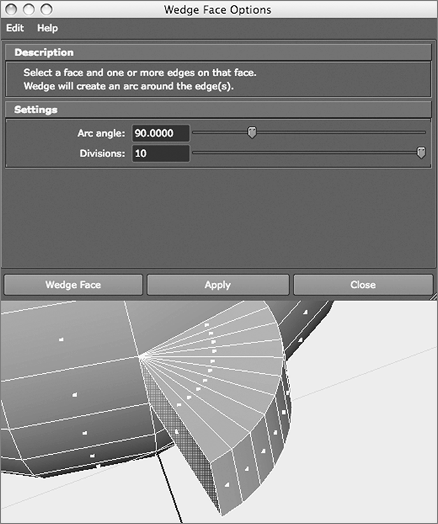
Figure 4-16: Executing a Wedge operation on a face of a sphere
RMB+click a mesh and select Multi from the marking menu. Select a face, Shift+select
one of the face’s edges, and choose Edit Mesh ⇒ FACE ⇒ Wedge
(under the FACE section of the menu).
In the option box, notice the Description heading. Under the Settings heading, you can select the degree of turn in the Arc Angle (90 degrees is the default) as well as the number of faces used to create the wedge (by moving the Divisions slider), as shown in Figure 4-16.
As a reminder, you can RMB+click an object to display a marking menu. Drag the cursor to select Multi and release the mouse button to be able to select a face and then an edge for the Wedge operation. Then, click or Shift+click your selection.
The Wedge tool is useful for items such as elbows, knees, archways, and tunnel curves.
The Poke Tool
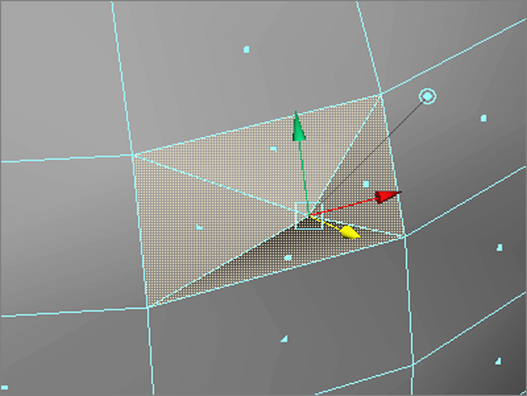
Figure 4-17: Poke helps create areas of detail in your model.
Poke is great for creating detailed sections of a mesh (poly surface) and bumps or indentations. To use the Poke tool to add detail to a face, select a face and then choose Edit Mesh ⇒ FACE ⇒ Poke.
A vertex is added to the middle of the face, and the Move manipulator appears on the screen for that new vertex, as shown in Figure 4-17. This lets you move the point to where you need it on the face. You can add bumps and depressions to your surface as well as create regions of extra detail. By selectively adding detail, you can subdivide specific areas of a polygon for extra detailed work, leaving lower poly counts in less-detailed areas for an efficient model.
The Bevel Tool
Use the Bevel tool to round sharp corners and edges. The Bevel tool requires that you select an edge or multiple edges and then use them to create multiple new faces to round that edge or corner.
Select an edge or edges
and choose Edit Mesh ⇒ EDGE ⇒ Bevel
(under the EDGE section of the menu)
to adjust your bevel. The Width slider sets the distance from the edge to the center
of where the new face will be. This basically determines the size of the beveled
corner. The Segments number defines how many segments are created for the bevel: The
more segments, the smoother the beveled edge. Leaving Segments at 1 creates a sharp
corner (see Figure 4-18).
The setting of the Roundness slider specifies the roundness of the corner. Setting the number too high will make the beveled edge stick out, as shown in Figure 4-19, although that can be a valid design choice. You can allow Maya to set the roundness automatically based on the size of the geometry being beveled. Select the Automatically Fit Bevel To Object check box to disable the Roundness slider. Move the Segments slider to set the number of new faces that are created on the bevel: The more segments, the smoother the bevel.
Use the Bevel tool to round polygonal edges. You can also use it to add extra surface detail because Bevel creates more faces on the surface.
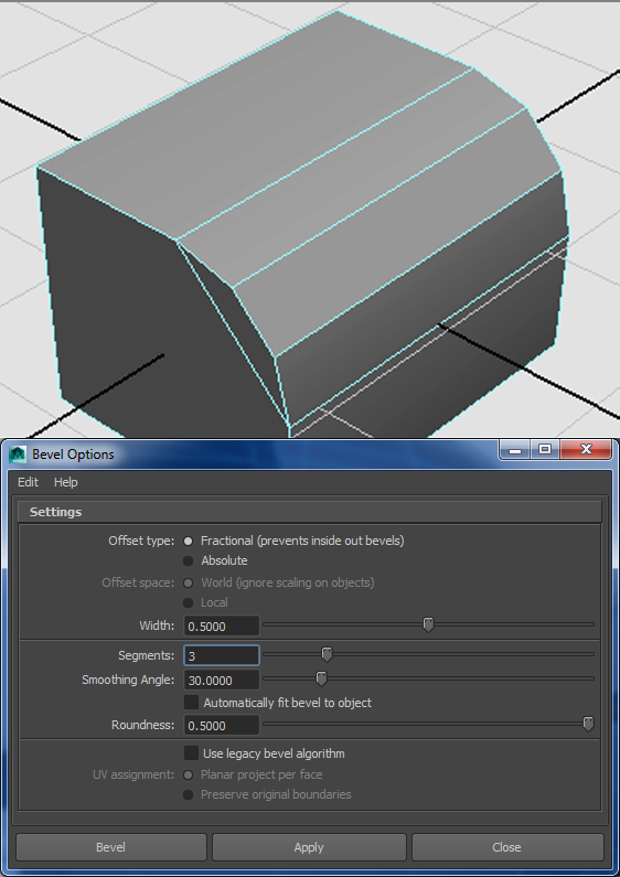
Figure 4-18: Increase Segments to create a rounder corner.
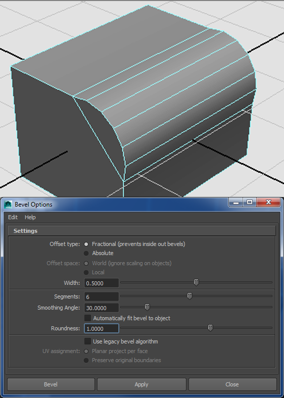
Figure 4-19: A poly bevel’s roundness set too high
Modeling Toolkit Bevel
Just like the Maya Extrude and the Modeling Toolkit Extrude, there is a way to bevel inside Modeling Toolkit. Using the same example as earlier, a simple cube, you’ll see how to bevel in the Modeling Toolkit here:
- Make sure the Modeling Toolkit Activate icon () is turned on and
enter edge selection mode.
- Select an edge on the cube. Press W for the Move tool. You can also
select Move from the Modeling Toolkit panel, but the traditional Maya hotkey of
W works the same while in Modeling Toolkit. But because you have Modeling
Toolkit enabled, your manipulator will have three circles instead of the squares
from Maya’s traditional Move manipulator. Just like with Maya’s squares, you can
click + drag any of the circles to see that you can move that edge in any
two-dimensional plane easily. Moving your mouse over any of the circles gives
you the plane axes (Figure
4-20). Undo any moves you may have done, and you’ll move on to the Modeling
Toolkit Bevel command next.
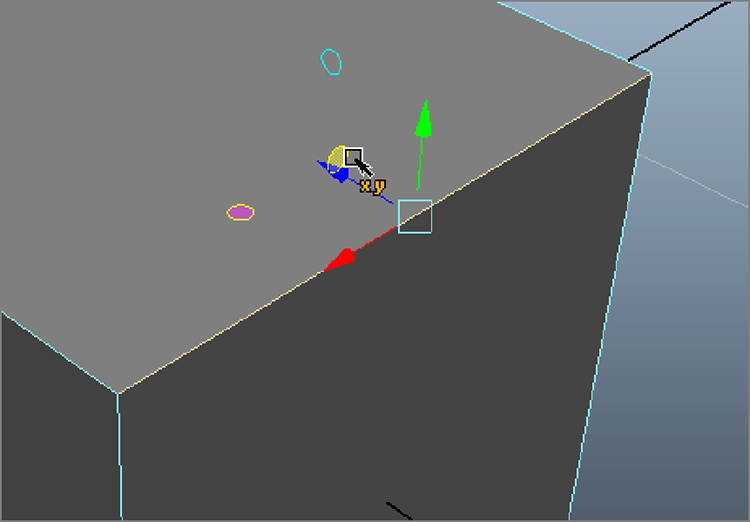
Figure 4-20: Modeling Toolkit also has easy planar movement handles to components with its three circles in the manipulator.
- With an edge selected, click the Bevel button in the Modeling Toolkit panel. You can select either Divisions or Offset and click and drag in the view panel to set their values. Offset is like Maya Bevel’s Width attribute and makes the bevel larger or smaller, while Divisions affects the rounding of the bevel. Figure 4-21 shows a Modeling Toolkit bevel with an Offset of 0.5 and Segments of 3, which matches the Maya bevel done earlier with a Width of 0.5 and Segments of 3. The result on the cube is the same if you compare it with the earlier Maya bevel shown in Figure 4-18.
- Click the Bevel button to exit the tool and commit your bevel operation to the cube.
As you can see, using Modeling Toolkit makes the Bevel tool slightly easier and faster to implement. As a matter of fact, Modeling Toolkit is only a workflow plug-in. It passes all of its changes and work into standard Maya attributes and nodes, making sharing files created using Modeling Toolkit workflow no different from ones created without Modeling Toolkit enabled. So, the cube you bevel in Modeling Toolkit is precisely the same as the one beveled in Maya software’s traditional workflow. The attributes and history on that object are the same.

Figure 4-21: The Modeling Toolkit bevel is the same as the Maya bevel shown in Figure 4-18.
Putting the Tools to Use: Making a Cartoon Hand
Starting with a simple polygonal cube, you’ll create a basic cartoon hand using a mix of Maya and Modeling Toolkit workflows.
Download the entire Poly_Hand project from the web page (www.sybex.com/go/introducingmaya2015) where you can also find a video for this tutorial. Set your project to this folder and follow these steps:
- With Interactive Creation turned off, create a polygonal cube. Open the Attribute Editor and, in the polyCube1 tab, set Subdivisions Width to 3, Subdivisions Height to 1, and Subdivisions Depth to 1. If you don’t have that tab in the Attribute Editor, click Undo to remove the cube, turn on History, and re-create the cube.
- Scale the cube to X = 4, Y = 1.3, and Z =
4.5 so that it looks as shown in Figure 4-22.
Figure 4-22: The poly cube in position to make the hand
- Turn on the Modeling Toolkit icon () in the status
bar. Click the Modeling Toolkit tab in the Channel Box to see the Modeling
Toolkit tools if you need them. RMB+click the cube and choose Face from the
marking menu.
- Select the front face that is in the corner closest to you. You’ll
extrude the face to make the first part of the index finger. Before you extrude,
though, rotate the face a bit in the Y-axis, away from the rest of the
hand, to angle the extrusion toward where the thumb would be, as shown in Figure 4-23 (left).
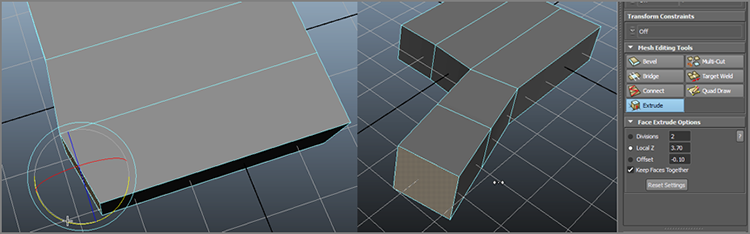
Figure 4-23: Rotate the face (left) and then extrude the index finger.
- In the Modeling Toolkit panel, click the Extrude button. Set Divisions
to 2. Click the Local Z radial button and enter
3.7 for the Extrude Local Z attribute in the
Channel Box. Set the Offset to -0.10 and exit the
Extrude tool. Figure 4-23 (right) shows the full index
finger with the slight rotation away from the hand from the previous step.
Save your work, and compare it to the scene file
poly_hand_v1.mbin the Poly_Hand project on the web page. - Repeat
steps 4 and 5 for the remaining two fingers. Remember, if you rotate the initial
face of each finger slightly away from the previous finger, the extrusions will
have small gaps between them, as shown in Figure 4-24. Otherwise, the fingers will extrude
right up against each other, like a glove with the fingers glued together. Also
remember to exit the Extrude tool in the Modeling Toolkit panel by clicking it
off after each extrusion is complete to move on to the next finger.
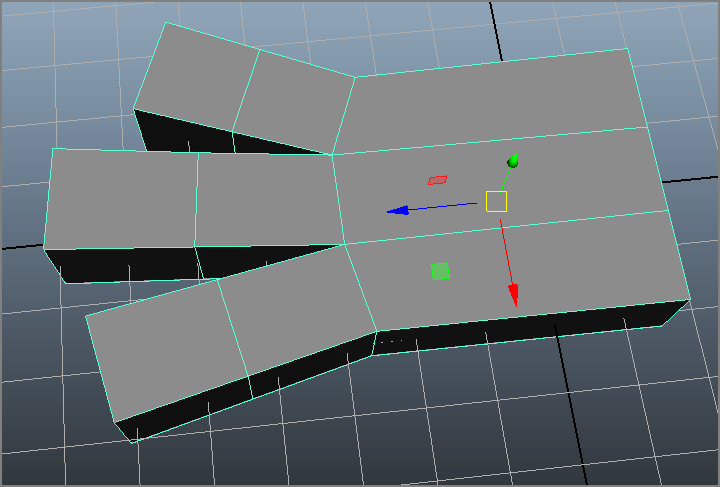
Figure 4-24: Three fingers
Use Table 4-1 as a guide for the extrusion lengths (Local Z value) for each finger.
Table 4-1: Extrusion length guide
Finger Extrude Local Z value Middle 4.2 Pinkie 3.0 When you’re finished with the three fingers, select the hand; in the Perspective panel, press 2 to give you a smooth preview of the hand. With a polygonal object, pressing the 1, 2, and 3 keys previews the smoothness your model will likely have when it’s smoothed (a polygonal modeling operation about to be discussed). Pressing 2 also shows the original shape of the hand as a wireframe cage (see Figure 4-25, left).
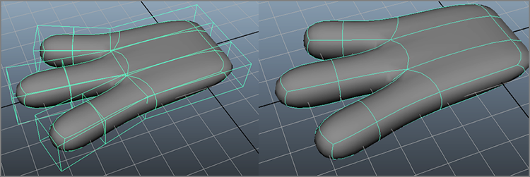
Figure 4-25: A smoothed preview of the hand, with the original shape shown as a cage (left) and a full smooth preview without the cage (right)
-
With the hand still selected, press 3. The original wireframe cage disappears, as shown in Figure 4-25 (right). This doesn’t alter your model in any way; if you render, your hand will still be blocky, just as you modeled it. Press 1 to exit the smooth preview and return to the original model view. The scene file
poly_hand_v2.mbshows the hand with the three fingers created. - Let’s work on the thumb. You need to insert some new divisions on the
body of the hand to extrude a thumb. With the hand selected, choose Mesh Tools ⇒ EDIT ⇒ Insert Edge Loop Tool and click
the side edge of the hand, as shown in Figure 4-26. A dotted line appears. Drag along the
edge you clicked to place the insertion and release the mouse button to place
the new loop of edges.
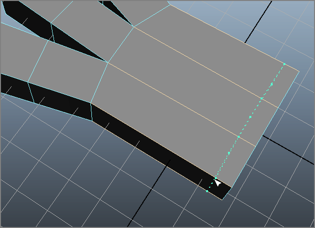
Figure 4-26: Insert an edge loop at the base of the hand.
- Insert a second loop of edges at the middle of the hand, as shown in Figure 4-27. Press W to exit the Insert Edge Loop tool.
- Rotate and then scale down the face, as shown in Figure 4-28, in the
Z-axis to get ready to extrude the thumb.
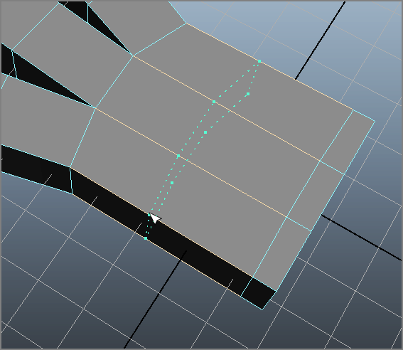
Figure 4-27: Insert a second loop of edges up toward the middle of the hand.
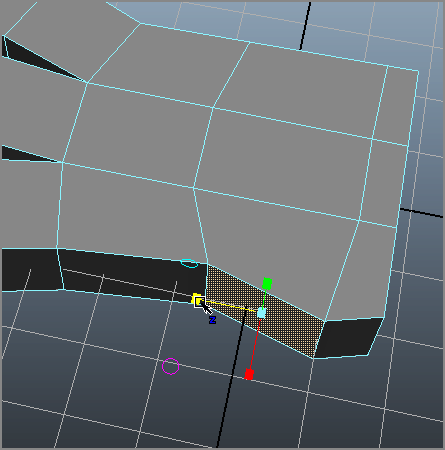
Figure 4-28: Scale and rotate the thumb’s face to get it ready to extrude.
- In
Modeling Toolkit, click Extrude and set Local Z to 3.0. Keep Offset at -0.10 and
Divisions to 2, as with the other three fingers
(see Figure 4-29).
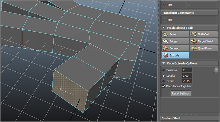
Figure 4-29: Extrude the thumb.
- Select the three faces at the base of the hand (where it would meet
an imaginary wrist) and scale them down in the X-axis and up in the
Y-axis to create a flare, as shown in Figure 4-30.
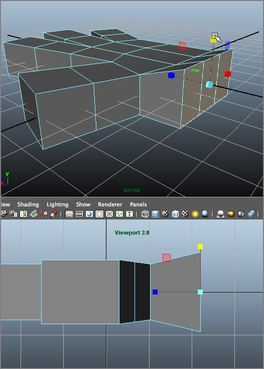
Figure 4-30: Create a flare at the base of the hand.
- If you press 3 to preview the hand smoothed, it will lose a good amount of its detail and become too soft. Let’s keep some of the angles of the hand by beveling the edges all around the hand. Select the outer edges all around the hand, as shown in Figure 4-31, in X-Ray view (which you invoke in a view panel by selecting in its menu bar Shading ⇒ X-Ray.). Make sure to get all the edges around the outside of the hand, fingers, and thumb.
- In Modeling Toolkit, click Bevel and set Offset to 0.4 and Segments to 1. Figure 4-32 shows the beveled hand without Smooth Preview (left) and with Smooth Preview (right).
- While in Smooth Preview, select the ring of faces around the base of
the thumb and scale them down a bit to accentuate the flare of the thumb, as
shown in Figure 4-33. Make any
additional adjustments to your liking by manipulating faces and vertices.
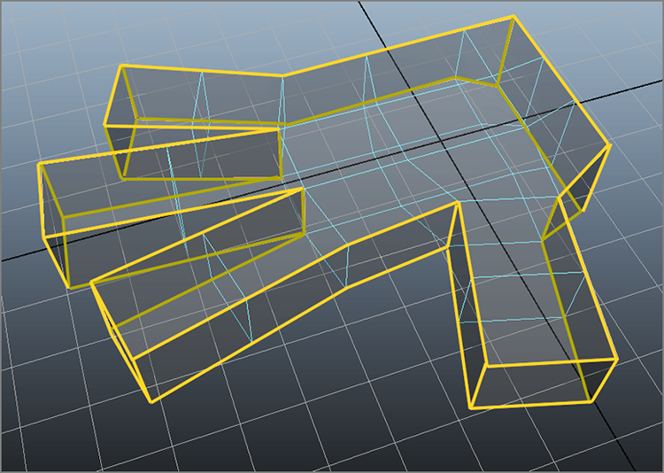
Figure 4-31: Select all the edges outlining the entire hand.
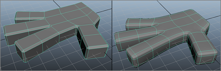
Figure 4-32: Beveling all around the hand (left) and shown with Smooth Preview (right)
Figure 4-33: Scale down these faces to flare the thumb a bit more.
- Exit Smooth Preview (press 1). To add more detail to the hand, you’ll
raise the knuckles. You need to create new vertices for the knuckles where each
finger meets the hand. Enter edge selection mode with Modeling Toolkit still
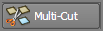
active. In the Modeling Toolkit panel, click the Multi-Cut icon (
 ). Click and drag
along the edge of the hand, right below where the index finger attaches to the
hand, until the yellow readout reads about 65%. Release the mouse button to lay
down the first point of the Multi-Cut operation.
). Click and drag
along the edge of the hand, right below where the index finger attaches to the
hand, until the yellow readout reads about 65%. Release the mouse button to lay
down the first point of the Multi-Cut operation. - Now click the opposite edge across at about 33%. You’ll notice a
green dashed line stretch across denoting where a new edge will be placed, as
shown in Figure 4-34 (left).
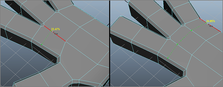
Figure 4-34: Use the Multi-Cut tool to lay down edges for the knuckles.
- Click across the remaining knuckle faces to lay down a cut line across the top of the hand, as shown in Figure 4-34 (right).
- Exit the Multi-Cut tool in the Modeling Toolkit panel to commit the
changes, and it will add three new edges (and hence three new faces) along the
back of the hand for the knuckles. Select each of those new faces and choose Edit Mesh ⇒ FACE ⇒ Poke (under the FACE section) to
subdivide them into five triangles, with a vertex in the center. A special
manipulator appears when you invoke the Poke command. Use the Z
translate handle to pull those middle vertices up to make knuckles (see Figure 4-35).
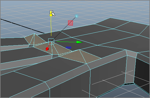
Figure 4-35: Use the Poke tool to raise the knuckles.
- Now that you have a cartoon hand, you can smooth out the mesh to make
it less boxy. In Object mode, select the hand, and press 3 to see a preview of
what the hand will look like after it’s smoothed. Press 1 to exit the smooth
preview. Choose Mesh ⇒ SHAPE ⇒ Smooth
(under the SHAPE section of the
menu); in the option box, under Exponential Controls, select Maya Catmull-Clark
for the Subdivision Type, set Division Levels to 2, and leave the other
options at their defaults (see Figure 4-36, left).
- Click Smooth. Your cartoon hand should take on a smoother, rounder look. This time, however, you’ve altered the geometry and actually made the mesh smoother and given it a higher density of polygons. Notice all the nodes listed under Inputs in the Channel Box in Figure 4-36 (right). This is because History has been on for the entire duration of this exercise. At any time, you can select one of those nodes and edit something—the extrusion of the pinkie, for example.
To verify that you’ve been working correctly, you can load the finished hand file
(with its history intact), which is called poly_hand_v3.mb, available
from the book’s web page, www.sybex.com/go/introducingmaya2015. If you don’t need any of the history
anymore, then with the hand selected, choose Edit ⇒ Delete By Type ⇒ History to get rid of all those extra
nodes.
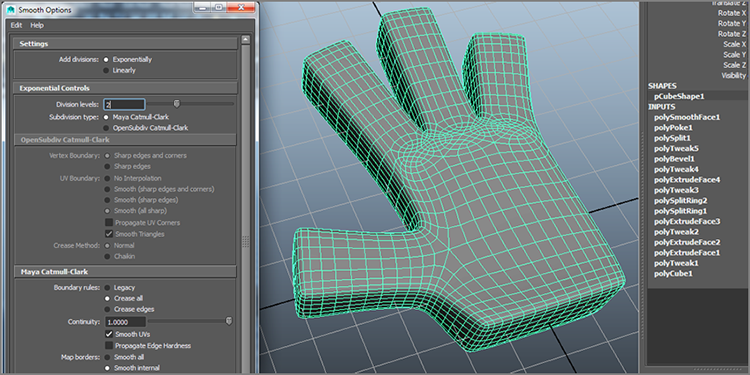
Figure 4-36: Set the options for the Smooth operation (left), and the smoothed hand is shown with all its history nodes (right).
Creating Areas of Detail on a Poly Mesh
As you saw with the cartoon hand, it became necessary to add more faces to parts of the surface to create various details, such as with the knuckles. Maya provides several ways to add surface detail or increase a poly’s subdivisions, as you’ve begun to see in the cartoon hand exercise. Let’s take a deeper look at these and more tools for adding detail to a mesh.
The Add Divisions Tool
You can use the Add Divisions tool to increase the number of faces of a poly surface
by evenly dividing either all faces or just those selected. Select the poly surface
face or faces and choose Edit Mesh ⇒ FACE ⇒ Add Divisions (under the FACE section
of the menu). Make sure not to select the first Add Divisions entry, which is under
the EDGE section of the menu; otherwise, you will split the edges surrounding the
selected face instead of splitting the face into more faces. In the option box, you
can adjust the number of times the faces are divided by moving the Division Levels
slider. With Add Divisions set to Exponentially under the Settings
heading, the Mode drop-down menu gives you the choice to subdivide your faces into
quads (four-sided faces, as on the left of Figure 4-37) or triangles (three-sided faces, as on the
right in Figure 4-37).

Figure 4-37: The Mode drop-down menu of the Add Divisions tool lets you subdivide faces into quads or triangles.
Figure 4-38: Dividing edges
You can also select a poly edge to divide. Running this tool on edges divides the selected edges into separate edges along the same face, giving you more vertices along that edge. It doesn’t divide the face; rather, you can use it to change the shape of the face by moving the new vertices or edge segments, as shown in Figure 4-38. Just make sure to select Add Divisions under the EDGE section of the Edit Mesh menu.
You use the Add Divisions tool to create regions of detail on a poly surface. This is a broader approach than using the Poke tool, which adds detail for more pinpoint areas.
Modeling Toolkit Multi-Cut Tool
As you saw when creating more faces and edges for the hand’s knuckles in the previous exercise, Modeling Toolkit’s Multi-Cut tool allows you to lay down edges along faces fairly easily. You access the Multi-Cut tool when Modeling Toolkit is enabled, under the Mesh Editing Tools heading. You can also make multiple cuts on the same face, as shown in Figure 4-39.
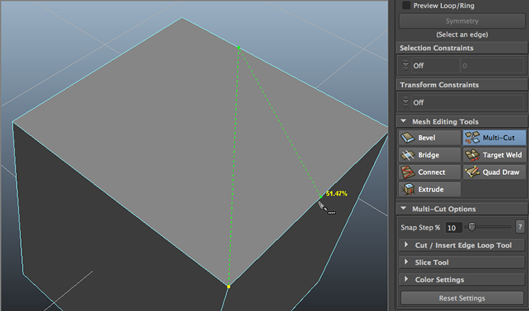
Figure 4-39: The Modeling Toolkit Multi-Cut tool
You can also access the Multi-Cut tool through Mesh Tools ⇒ EDIT ⇒ Multi-Cut Tool (under the EDIT section of the menu).
The Insert Edge Loop Tool
Figure 4-40: Using the Insert Edge Loop tool
This handy tool adds edges to a poly selection, much like the Multi-Cut tool, but it does so more quickly by working along the entire poly surface, along common vertices. The Insert Edge Loop tool automatically runs a new edge along the poly surface perpendicular to the subdivision line you click, without requiring you to click multiple times as with the Modeling Toolkit Multi-Cut tool. You used this tool in the decorative box in Chapter 3 and earlier in this chapter on the cartoon hand and will continue using it throughout this book. You’ll find it indispensable in creating polygonal models because it creates subdivisions quickly.
For instance, subdividing a polygonal cube is quicker than using the Multi-Cut tool. With a poly cube selected, choose Mesh Tools ⇒ EDIT ⇒ Insert Edge Loop Tool. Click an edge, and the tool places an edge running perpendicular from that point to the next edge across the surface and across to the next edge, as shown in Figure 4-40. If you click and drag along an edge, you can interactively position the new split edges.
The Offset Edge Loop Tool
Much like the Insert Edge Loop tool, the Offset Edge Loop tool (Mesh Tools ⇒ EDIT ⇒ Offset Edge Loop Tool) inserts not one but two edge loop rings of edges across the surface of a poly. Edges are placed on both sides of a selected edge, equally spaced apart. For example, create a polygon sphere and select one of the vertical edges, as shown in Figure 4-41. Maya displays two dashed lines on both sides of the selected edge. Drag the mouse to place the offset edge loops; release the mouse button to create the two new edge loops.
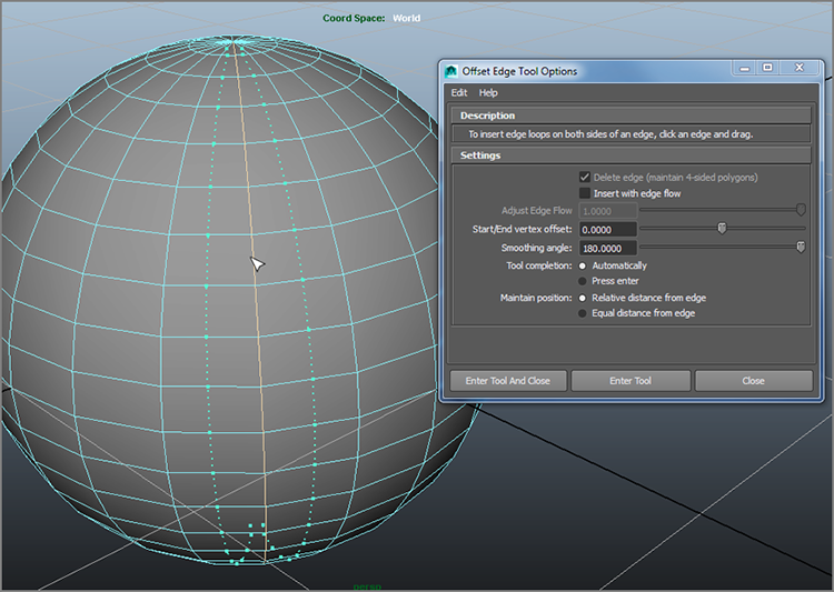
Figure 4-41: The Offset Edge Loop tool and its options
The Offset Edge Loop tool is perfect for adding detail symmetrically on a surface quickly.
Modeling Toolkit Connect Tool
Similar to the Insert Edge Loop tool is the Modeling Toolkit Connect function. While in Modeling Toolkit, simply select an edge and click the Connect button in the Modeling Toolkit panel. This will create edges going around the object perpendicular to the selected edge. The Slide attribute places the perpendicular cut along the selected edge, which is slightly less interactive than Insert Edge Loop. However, the Segments attribute allows you to insert more than one ring of edges, while Pinch spaces those extra segments evenly (Figure 4-42). You can also select Mesh Tools ⇒ EDIT ⇒ Connect Tool in the main menu bar.
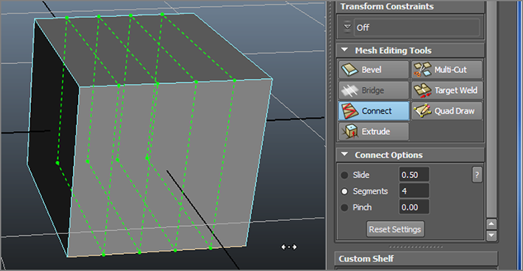
Figure 4-42: The Modeling Toolkit Connect tool creates edges much like Insert Edge Loop.
Modeling Toolkit Drag and Bridge Tool
One of Modeling Toolkit’s nicest features is its drag selection mode. This allows you to essentially click and drag your cursor over the components you want selected with your cursor instead of having to click every component, almost like painting.
Try This
- Create a cube in an empty scene and set Subdivisions Width to 1, Subdivisions Height to 4, and Subdivisions Depth to 5, as shown in Figure 4-43. Figure 4-44 is shown in X-Ray mode (which is enabled in the Perspective panel’s menu bar by choosing Shading ⇒ X-Ray).
- You are going to delete a square shape out of the front and back of the box. Exit X-Ray view mode if you are currently in X-Ray (view panel menu: Shading ⇒ X-Ray).
- Make sure the Modeling Toolkit panel is open. Enter into face selection mode through the marking menu.
- In the Modeling Toolkit panel, select the Drag option under the
transformation icons, as shown in Figure 4-44. Your
selection cursor changes to a circle. Click one of the inside faces, and drag
along a six-face square in the middle of the front of the cube, also in Figure 4-44.
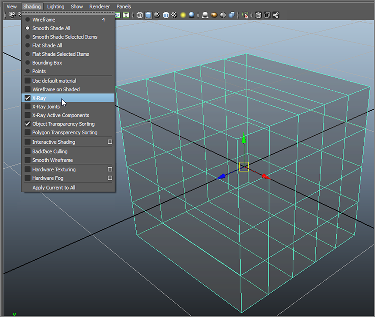
Figure 4-43: Create a subdivided box.
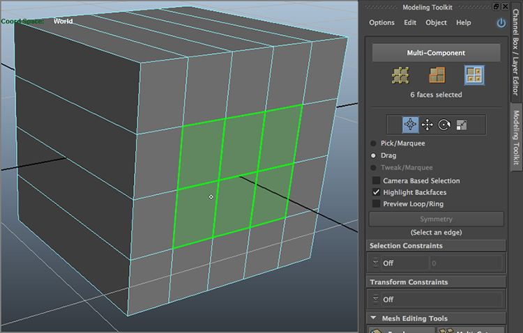
Figure 4-44: Drag+select a six-face square on the front of the box.
- Orbit
your view to see the back of the box, hold down Shift, and Drag+select the same
six-face square on the back of the box.

Figure 4-45: Delete the square shapes out of the box.
- Press Delete on your keyboard to delete the 12 selected faces, leaving you with a hollow box, as shown in Figure 4-45.
- Now you’re going to “fill in” the box to make a square-shaped tube. Switch to edge selection, and select the Pick/Marquee option in the Modeling Toolkit panel (it’s right above the Drag option). Click to select the two front and back edges shown in Figure 4-46 (left).
- In the Modeling Toolkit panel, click Bridge, and two new faces will
appear connecting the selected edges (Figure 4-46,
right). Exit the Bridge tool.
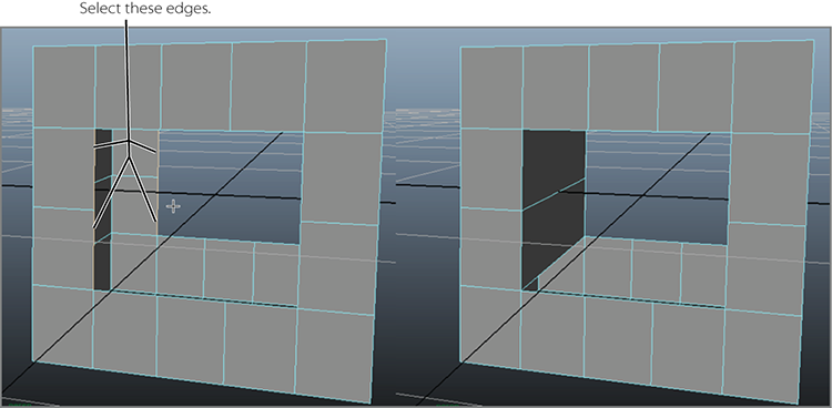
Figure 4-46: Select these edges (left) and bridge them (right).
- Repeat steps 7 and 8 on the bottom three edges to connect the bottom, as shown in Figure 4-47.
- Repeat for the remaining edges to fill the holes making a square pipe that is now solid on the inside.
Experiment with the Divisions attribute for the Modeling Toolkit Bridge to get a curvature in the bridged faces.
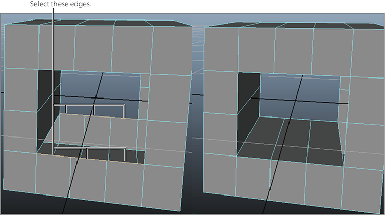
Figure 4-47: Bridge the bottom faces.
Modeling Toolkit Symmetry Selections
One of the charms of Modeling Toolkit is its ability to select in symmetry, meaning the components you select on one side of a surface are automatically selected on the other side, making modeling appreciably faster. While Maya has its own Symmetry feature in the transformation tools (Move, Rotate, Scale) covered in Chapter 3, it is limited to simple transforms. Tools such as Extrude or Bevel will not work in Maya’s symmetry mode. Let’s see how Modeling Toolkit Symmetry works.
Try This
- Create a polygon sphere in a new scene. Press 5 for Shaded view, and make sure Modeling Toolkit is open.
- Select an edge on the sphere that you want to be the centerline for
the symmetry.
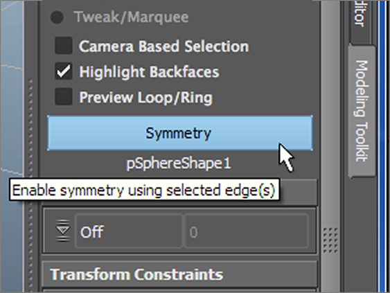
Figure 4-48: Turn on Symmetry mode.
- In the Modeling Toolkit panel, check the symmetry. Once you do, the sphere’s object name will display next to the check box, as shown in Figure 4-48.
- Now enter face selection. As you move your mouse before you select, it is mirrored, and when you do select a face or faces, that selection will be mirrored on the other side of the mesh (Figure 4-49).
Now if you engage any poly editing function, it will act on the symmetrically selected components.
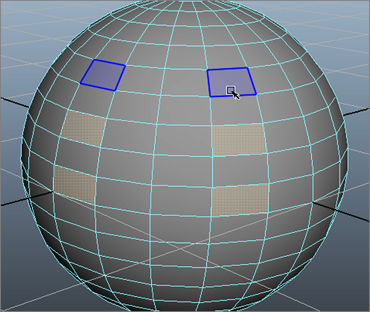
Figure 4-49: Selecting faces on one side selects them on the other.
Combine, Merge Components, and the Merge Vertex Tool
The Combine function is important in cleaning up your model and creating a unified single mesh out of the many parts that form it. When modeling, you’ll sometimes use several different polygon meshes and surfaces to generate your final shape. Using Combine, you can create a single polygonal object out of the pieces.
Frequently, when you’re modeling a mesh, you’ll need to fold over pieces and weld parts together, especially when you combine meshes into a single mesh. Doing so often leaves you with several vertices occupying the same space. Merging them simplifies the model and makes the mesh much nicer to work with, from rigging to rendering. The Merge Components tool fuses multiple vertices at the same point into one vertex on the model. And the Merge Vertex tool from Modeling Toolkit is a more interactive way to fuse vertices together. We’ll take a look at both in order to compare the workflows.
In the following simple example, you’ll create two boxes that connect to each other along a common edge, and then you’ll combine and merge them into one seamless polygonal mesh. To begin, follow these steps:
- In a new scene, create two poly cubes and place them apart from each other, more or less as shown in Figure 4-50.
- Select the bottom edge of the cube on the right that faces the other cube and choose Edit Mesh ⇒ EDGE ⇒ Extrude (in the EDGE section of the menu). Pull the edge out a little to create a new face, as shown in Figure 4-51. This will be a flange connecting the two cubes. It isn’t important how far you pull the edge out; you’ll connect the two cubes by moving the vertices manually.
- Select the first corner vertex on the newly extruded face, and snap it
into place on the corner vertex of the other cube, as shown in Figure 4-52 (left). Remember,
you can click the Snap To Points icon (
 ) to snap the vertex onto the cube’s corner.
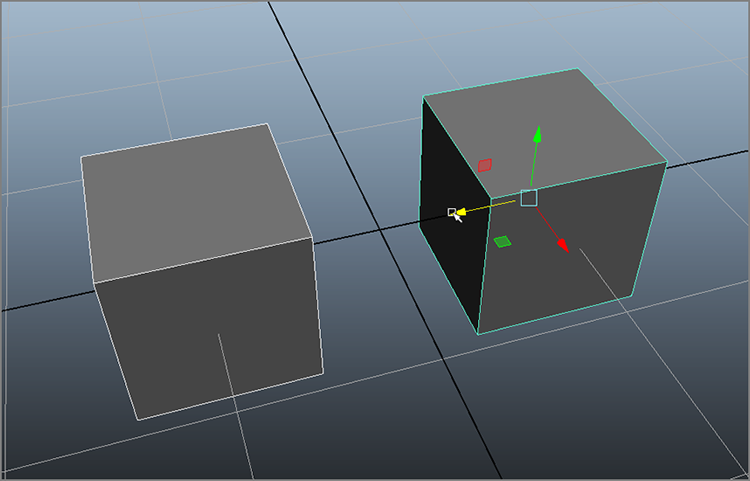
Figure 4-50: Place two polygonal cubes close to each other.

Figure 4-51: Extrude the bottom edge to create a flange.
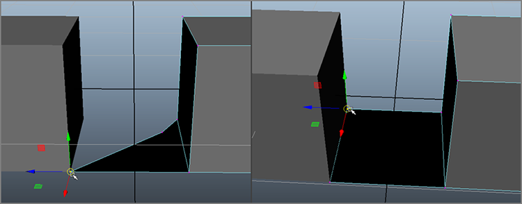
Figure 4-52: Snap the first corner vertex to the newly extruded face (left), and then the second (right).
- Snap the other vertex to the opposite corner so that the cubes are
connected with a flange along a common edge, as shown in Figure 4-52 (right).
Even though the cubes seem to be connected at a common edge, they’re still two separate polygonal meshes. You can easily select and move just one of the stacked vertices and disconnect the connective face of the two cubes. You need to merge the stacked vertices of the cubes into a single vertex. However, the Merge Components function won’t fuse vertices from two separate meshes together; you must first combine the cubes into a single poly mesh. The following steps continue this task.
- Select the two cubes (one has the extra flange on the bottom, of course) and choose Mesh ⇒ COMBINE ⇒ Combine. Doing so makes a single poly mesh out of the two cubes. You can now use the Merge Components function.
- Even though the cubes are now one mesh, you still have two vertices at
each of the connecting corners of the cube on the left. Click on the vertex in
the front corner of the newly combined boxes, and pull the vertex back as shown
in Figure 4-53 (left) to disconnect the flange
at one end. (Click the vertex to select just one. Don’t use a marquee selection,
which will select both vertices at once.)

Figure 4-53: There are still two different vertices at the corner, and the boxes aren’t really connected (left). The back corner is now connected properly (right).
- Let’s start at the back corner. To merge the vertices at that corner, select both the vertices that are on top of each other at the far corner by using a marquee selection and then choose Edit Mesh ⇒ Merge Components to fuse the two vertices sitting on top of each other together. As you can see in Figure 4-53 (right), clicking on the back corner vertex and moving it reshapes both cubes since the corner is now fused together.
- Now for the front corner where we peeled back the vertex to create a
gap in Step 6, this time using the Merge Vertex Tool instead. In this case, we
do not need to have the two vertices sitting on top of each other or even close
together as we need with Merge Components. Choose Mesh Tools ⇒ EDIT ⇒ Merge Vertex Tool. Click on the
corner vertex on the flange on the cube on the right and then drag your cursor
to highlight the corner vertex on the box on the left as shown in Figure 4-54. And now the near
corner of this mesh is fused into a single vertex.
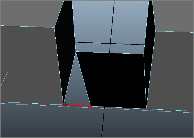
Figure 4-54: Merge Vertex tool in action.
You’ll notice fewer errors and issues with clean models when you animate, light, and render them. Combining meshes makes them easier to deal with, and Merge Components and the Merge Vertex tool cut down on unwanted vertices.
The Slide Edge Tool
If you need to move an edge on a model, selecting the edge or edges and using the Move tool will change the shape of the mesh. Let’s see how this works:
- Choose Create ⇒ Polygon
Primitives ⇒ Cone
and set the Height Divisions to 2
as shown in Figure 4-55 (left).
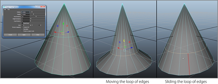
Figure 4-55: Create a cone (left). The middle image shows what happens to the cone when you move the middle loop of edges as opposed to using the Slide Edge tool as shown on the right.
- RMB+click and select Edges, and then double click on the middle row of horizontal edges to select the entire loop. Move the loop of selected edges down, and the cone turns into a pointy (Figure 4-55 [middle]).
- Press Z for undo to return the object back to its original cone shape. Now, with the same loop of edges selected, choose Mesh Tools ⇒ EDIT ⇒ Slide Edge Tool and MMB+drag on one of the vertical edges (the vertical edge you MMB+click+ drag on will turn red) of the cone to slide the selected loop of edges up and down the cone without changing its shape, as shown in Figure 4-55 (right).
The Slide Edge tool is perfect for moving edges on a complex mesh surface without altering the shape of that surface.
The Cut Faces Tool
The Cut Faces tool lets you cut across a poly surface to create a series of edges for subdivisions, pull off a section of the poly, or delete a section (see Figure 4-56). Select the poly object, and choose Mesh Tools ⇒ EDIT ⇒ Cut Faces Tool. Click the option box if you want to extract or delete the section.
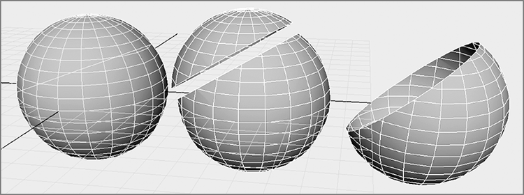
Figure 4-56: The Cut Faces tool can be used to create the edges, pull apart the poly object, or cut off a whole section.
You can use the Cut Faces tool to create extra surface detail, to slice portions off the surface, or to create a straight edge on the model by trimming off the excess.
The Duplicate Face Tool
Select one or more faces and choose Edit Mesh ⇒ FACE ⇒ Duplicate to create a copy of the selected faces. You can use the manipulator that appears to move, scale, or rotate your copied faces.
The Extract Tool

Figure 4-57: Pull off the faces.
The Extract tool is similar to the Extrude tool, but it doesn’t create any extra faces. Select the faces and choose Mesh ⇒ SEPARATE ⇒ Extract to pull the faces off the surface (see Figure 4-57). If the Separate Extracted Faces option is enabled, the extracted face will be a separate poly object; otherwise, it will remain part of the original.
This tool is useful for creating a new mesh from part of the original mesh you are extracting from. You can also use the Extract tool to create a hole in an object and still keep the original faces. When you use this tool with the Multi-Cut tool to make custom edges, you can create cutouts of almost any shape. You’ll see this functionality of creating custom shaped holes with the Split Mesh with Projected Curve function explored below as well.
The Smooth Tool
The Smooth tool (choose Mesh ⇒ SHAPE ⇒ Smooth) evenly subdivides the poly surface or selected faces, creating several more faces to smooth and round out the original poly object, as you saw earlier in this chapter with the cartoon hand model exercise.
Creating a Hole in a Mesh Surface Using Split Mesh with Projected Curve
Sometimes you need to cut a hole in a mesh. You can simply select faces on that mesh and delete them to create a hole. However, if you need a more intricate, custom-shaped hole, you’ll need to first use Split Mesh with Projected Curve to make a custom shape.
- Create a polygon sphere in a new scene.
- Now you’ll create a curve directly on the sphere to outline the hole’s
shape. With the sphere selected, press the
Make the selected object
                        live
icon in the status bar next to the snapping icons ( ). The text box
next to this icon will change from stating
). The text box
next to this icon will change from stating No Live SurfacetopSphere1and will turn blue ( ). Making an object
live will enable you to perform some functions directly on that mesh.
). Making an object
live will enable you to perform some functions directly on that mesh. - Choose Create ⇒ EP Curve Tool
to draw a line. Click on the sphere and a little X appears. Click again and a
line begins to appear. Click a number of points to create an interesting shape,
and because the sphere is Live, these curve points will be placed on top of the
sphere, as shown in Figure 4-58
(top). You can simply snap the final EP you draw on top of the first EP you drew
with point snaps () to close the curve shape. In the Outliner the line is called
curve1. More on creating curves can be found in Chapter 5. - We need to project this curved shape on to the sphere, because it is
still a separate object despite you creating it on top of the sphere. First,
disable Make Live by clicking its icon () again.
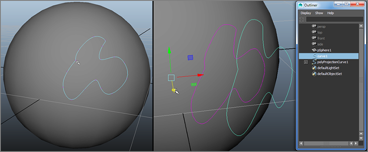
Figure 4-58: Draw an EP curve directly on the sphere (left). The projected curve (seen on the sphere in pink) adjusts if you move the original curve (seen away from the sphere in green).
- Next,
select the sphere and then the curved line and choose Edit Mesh ⇒ CURV ⇒ Project Curve on Mesh. Now if you
select
curve1in the Outliner (Figure 4-58, right) and move it around in your scene, the projected curve on the sphere (seen in your scene as pink) will adjust, staying on the sphere as shown in Figure 4-58 (right). - Now we can use this projected curve to outline a new set of edges on
our sphere! In the Outliner, select the sphere and the projected curve
(
polyProjectionCurve1) and choose Edit Mesh ⇒ CURVE ⇒ Split Mesh with Projected Curve. - Maya creates a new sphere that is subdivided with the new edges you
drew, as you can see in the Outliner in Figure 4-59 (left). You can delete the original
sphere and curve you drew (
pSphere1andcurve1), as well as the projected curve (polyProjectionCurve1), leaving you withpSphere2.
Figure 4-59: Splitting the sphere with its projected curve (left), and then deleted those faces to make a custom hole (right).
- Now simply delete the faces inside that shape, and you have your custom hole as shown in Figure 4-59 (right)!
Projecting a line shape onto a mesh surface will allow you to not only cut holes as in this exercise, but it’s also very handy for easily creating custom lengths of edges for modeling use.
The Sculpt Geometry Tool
You can use a Maya feature called Artisan to sculpt polygonal surfaces. Artisan is a
painting system that allows you to paint attributes or influences directly onto an
object. When you use Artisan through the Sculpt Geometry tool, you paint on a
polygon surface to move the vertices in and out, essentially to mold the surface, as
you will see with the candle modeling exercise in Chapter 5, “Modeling with NURBS
Surfaces and Deformers.” In that chapter you will use this tool to add detail to a
polygon model. Once you have played with the Sculpt Geometry tool in Chapter 5, try
loading the poly_hand_v3.mb model and sculpting some detail into the
cartoon hand.
To access the tool in polygon modeling, select your poly object and choose Mesh Tools ⇒ EDIT ⇒ Sculpt Geometry Tool
.
If you create a poly with a large number of subdivisions, you’ll have a smoother result when using the Sculpt Geometry tool (see Figure 4-60).

Figure 4-60: The Sculpt Geometry tool deforms the surface.
Modeling a Catapult
You’re going to create a catapult in this exercise using nothing but polygons. You’ll use some sketches as a reference for the model. Since this is a more involved object than a hand, it’s much better to start with good plans. This, of course, involves some research, web surfing, image gathering, or sketching to get a feel for what it truly is you’re trying to make.
To begin, create a new project for all the files called Catapult, or copy the Catapult project from the companion website (www.sybex.com/go/introducingmaya2015) to your hard drive. If you do not create a new project, set your current project to the copied Catapult project on your drive. Choose File ⇒ Set Project and select the Catapult project downloaded from the companion website. Remember that you can enable Incremental Save to make backups at any point in the exercise.
Now, let’s use a design already sketched out for reference. To begin, study the design sketches included in the sourceimages folder of the project. These sketches set up the intent rather easily.
In Chapter 8, “Introduction to Animation,” you’ll animate the catapult. When building any model, it’s important to keep animation in mind, especially for grouping related objects in the scene hierarchy so that they will move as you intend. Creating a good scene hierarchy will be crucial to a smooth animation workflow, so throughout this exercise you’ll use the Outliner to keep the catapult’s component pieces organized as you create them.
The Production Process
The trick with a complex object model is to approach it part by part. Deconstruct the major elements of the original into distinct shapes that you can approach one by one. The catapult can be broken down to five distinct objects, each with its own subobjects:
- Base
- Wheels
- Fulcrum assembly
- Winch assembly
- Arm assembly
You will model each part separately based on the sketch in Figure 4-61 and the detailed schematic in Figure 4-62.
The Base
The base consists of simple polygonal cubes representing timber and arranged to connect to each other. Keep in mind that in this exercise Interactive Creation for primitives is turned off (select Create ⇒ Polygon Primitives and make sure Interactive Creation is unchecked). Also, in the Perspective view, choose Shading ⇒ Wireframe On Shaded to turn on the wireframe lines while in Shaded mode to match the figures in this exercise.
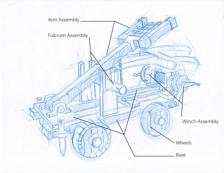
Figure 4-61: A sketch of the catapult to model
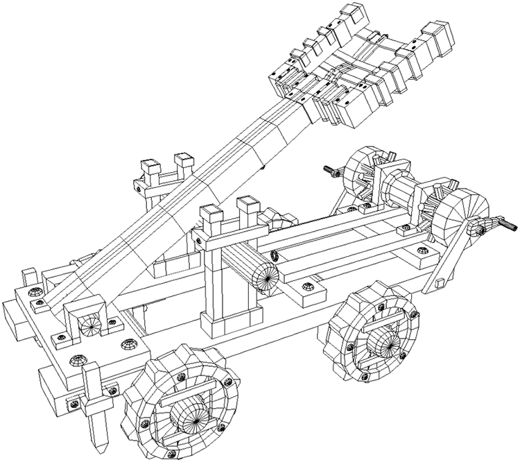
Figure 4-62: A schematic diagram of the finished model to illustrate the goal
Creating the Base Objects
To begin the catapult base, follow these steps:
- Choose Create ⇒ Polygon Primitives ⇒ Cube to lay down your first cube. This will be for the two long, broad boards running alongside.
- Scale the cube to 2.0 in X, 0.8 in Y, and 19.5 in Z. Move it off the center of the grid about 2 units to the right.
- Now you’ll add some detail to the simple cube by beveling the sides,
using either Modeling Toolkit or the traditional Bevel. Select the four edges
running on top of the board. In the main menu bar, select Edit Mesh ⇒ EDGE ⇒ Bevel
. Set Width to 0.1, set Segments to 2, and click Apply. Figure 4-63 shows the resulting board.

Figure 4-63: Create a bevel for the baseboard object.
- Select the remaining edges on the board, bevel them to a Width of
0.5, and set Segments to 2. See Figure 4-64. If you use Modeling Toolkit, enter an Offset value of
0.5 and a Segments value of 2.
Figure 4-64: Beveling the bottom edges
- Select the board and choose Edit ⇒ Duplicate to place a copy of the
board exactly where the original is in the scene. The new duplicated board is
already selected for you, so just move the copy about 4 units to the left. You
should now have something similar to Figure 4-65 (top).
Figure 4-65: The long boards at the base (top) and the platform board is in place (bottom).
- Now for the cross braces and platform. Create a poly cube and scale it to 7.25 in X, 0.6 in Y, and 3.25 in Z. Place this platform on top of the two beams, at the end of the catapult’s base.
- With the first board that you beveled, you had a different bevel for
the top edges than the bottom and sides. For this board, you’ll have the same
bevel width for all edges. Select the cube (not the edges as before) and choose
Edit Mesh ⇒ EDGE ⇒ Bevel
. Set Width to 0.2, set Segments to 2, and click Bevel (or Apply). Figure 4-65
(bottom) shows the platform board in place and beveled.
- Create a cube for the first of the top two cross braces, and scale it 6.5 in X, 0.6 in Y, and 1.2 in Z. Place it on top of the beams at the head of the base, and bevel this cube exactly as in the previous step.
- Duplicate the cube, and move the copy about a third of the way down
toward the end (Figure 4-66).
Figure 4-66: Cross bracing the base
Using Booleans
You’re going to add some detail as you go along, namely, the large screws that hold the timber together. The screws will basically be slotted screw heads placed at the intersection of the pieces. In this section, you will use Booleans to help create the screw heads.
Booleans are impressive operations that allow you to, among other things, cut holes or shapes in a mesh fairly easily. Basically, a Boolean is a geometric operation that creates a shape from the addition of two shapes (Union), the subtraction of one shape from another (Difference), or the common intersection of two shapes (Intersection).
Be forewarned, however, that Boolean operations can be problematic. Sometimes you get a result that is wrong—or, even worse, the entire mesh disappears and you have to undo. Use Booleans sparingly and only on a mesh that is clean and prepared. You’ve cleaned and prepped your panel mesh, so there should be no problems. (Actually, there will be a problem, but that’s half the fun of learning, so let’s get on with it.)
First, you need to create the rounded screw head.
- Create a polygonal sphere (Create ⇒ Polygon Primitives ⇒ Sphere) and move it from the origin off to the side in the X-axis of the base model. Scale the sphere down to 0.15 in XYZ.
- With the
sphere still selected, switch to the front view and press F to frame. RMB+click
the sphere and select Face from the marking menu (Figure 4-67). Select the bottom half of the sphere’s
faces and press Delete on your keyboard to make a hemisphere (Figure 4-68).
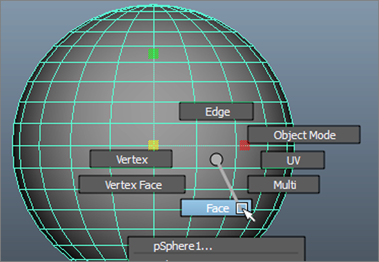
Figure 4-67: Use the marking menu to set the selection to Face.
Figure 4-68: Delete the bottom half of the faces.
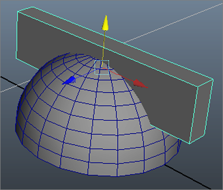
Figure 4-69: Place the scaled cube over the screw head.
- RMB+click the hemisphere and select Object Mode from the marking menu;
this exits face selection mode. Create a poly cube and scale it to 0.4, 0.1,
0.04. Place it over the hemisphere as shown in Figure 4-69.
Now you have both objects that you need for a Boolean operation, and they are placed properly to create a slot in the top of the screw head.

Figure 4-70: Selecting a Difference Boolean
- Select the hemisphere and then the cube set into it. Select Mesh ⇒ COMBINE ⇒ Booleans ⇒ Difference (Figure 4-70). The cube
disappears, and the screw head is left with a slot in the top, as shown in Figure 4-71.
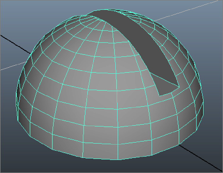
Figure 4-71: The screw head is slotted.
Ngons!
Now if you take a good close look at the screw head, especially where the slot is, you will notice faces that have more than four sides, which makes them Ngons. As I noted earlier in the chapter, faces that have more than four edges may be problematic with further modeling or rendering. This simple screw head most likely will not pose any problems in the application here, but let’s go over how to prevent any problems early on. You will select the potential problem faces (those around the slot) and triangulate them.
- Select all the faces around the slot, as shown in Figure 4-72 (left). Choose Mesh ⇒ SHAPE ⇒ Triangulate. This is the easiest
and fastest way to subdivide these faces from being Ngons without having to use
the Multi-Cut tool to manually fix them. And although it may not look as clean
as before (Figure 4-72, right), the geometry is clean
and will not be a potential problem like Ngons would be.
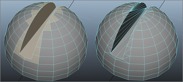
Figure 4-72: Select the faces around the slot (left) and triangulate them (right).
- Select the screw head, and choose Edit ⇒ Delete By Type ⇒ History. This cleans out any history on the object now that you’re satisfied with it.
- Notice that the screw head’s pivot point is at the origin. With the object selected, choose Modify ⇒ Center Pivot.
- Name the object ScrewHead and position it at one of the intersections of the boards you’ve built so far.
- Duplicate that first screw head and place the copies one by one at all
the other intersections on the base, as shown in Figure 4-73. These are pretty big screws, huh? For
this simple catapult, they’ll do fine. The workflow to make more realistic
screws is the same if you want to make this again with more realism and scale.
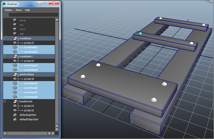
Figure 4-73: Place the screw heads on the base and organize your scene.
- Now take the objects in the scene and group them into a logical order, as shown in the Outliner in Figure 4-73.
Save your file, and compare it to catapult_v1.mb in the Catapult project
from the companion website to see what the completed base should look like.
The Winch Baseboards
Next to model for the base are the bars that hold the winch assembly to the base. Refer to the sketch of the catapult (Figure 4-60, earlier) to refresh yourself on the layout of the catapult and its pieces. Follow these steps:
- Create two long, narrow, beveled poly cubes for the baseboards of the
winch, and position them across the top two side braces. Put a couple of screws
on the middle crossbeam (see Figure
4-74).
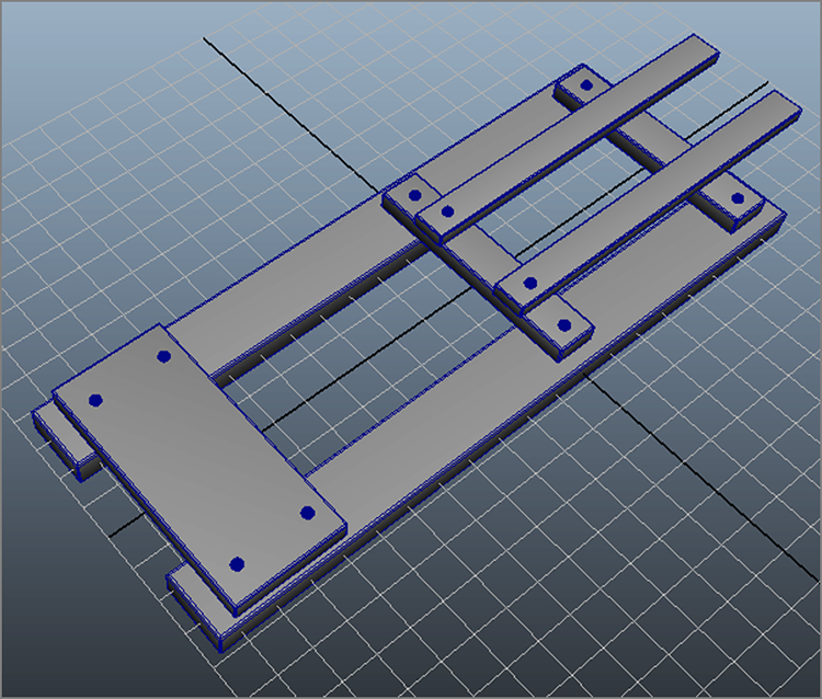
Figure 4-74: Adding the winch baseboards
- For the brackets that hold down the winch, create a small poly cube
and move it off to the side of the base to get it out of the way. Scale the cube
to 0.5, 0.3, 0.45. Enable Modeling Toolkit, select the side face, and click the
Extrude button in the Modeling Toolkit panel. Type 0.8 for the Local Z attribute and click the Extrude button off to
commit the extrusion, as shown in Figure 4-75.
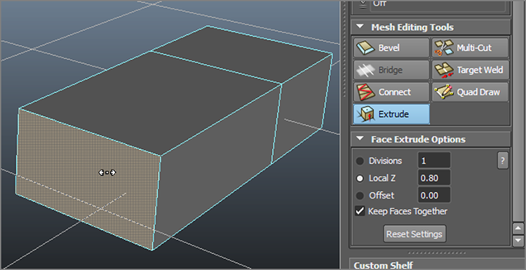
Figure 4-75: Use Modeling Toolkit Extrude to extrude the face.
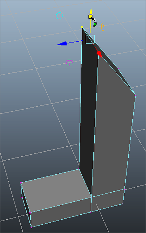
Figure 4-76: Extrude the top out to create an L shape; then move the vertices up to angle the top of the L.
- Select the top face of the original cube and use the Modeling Toolkit Extrude tool to extrude it to a Local Z of 1.54 to take it up to an L shape. Select the two inside vertices on the top of the L and move them up to create about a 45-degree angle at the tip, as shown in Figure 4-76.
- Select that angled face and select Edit Mesh ⇒ FACE ⇒ Extrude (in the FACE section of
the menu) for a Maya extrusion. Click the cyan-colored switch icon above the
Extrude manipulator (shown next to the cursor in Figure 4-77, left). This will switch the extrusion
axis (Figure 4-77, center) so you can pull the faces
out straight and not angled up. Then grab the Z Move manipulator and
pull the extrusion out about 0.75 units.
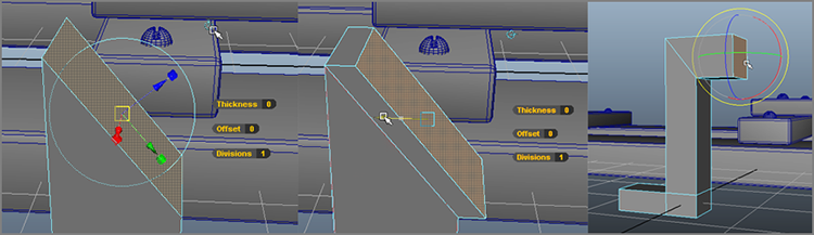
Figure 4-77: Click the switch icon (left) to switch the axis of extrusion (center). Rotate and scale the face to square it (right).
- Press W to exit the Extrude tool and enter Rotate. Select the end face and rotate it to make it flat vertically and scale it down in Y-axis to prevent it from flaring upward (Figure 4-77, right).
- This shape forms half of the braces you need. To create the other
half, select the face shown in Figure 4-78 (left) and delete it (press Delete). Enter Object mode,
select the mesh, and choose Mesh ⇒ MIRROR ⇒ Mirror Geometry
. Set Mirror Direction to -Z, and
leave the options as shown in Figure 4-78 (right).
Click Mirror, and you will have a full bracket.
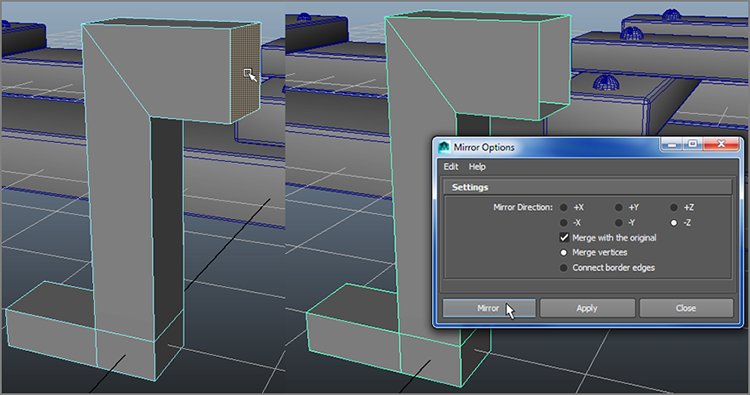
Figure 4-78: Delete the face (left) and set the Mirror Geometry options (right).
- Name the object bracket, and move it on top of one of the baseboards for the winch; then place a duplicated screw head on the flanges of the bracket. Group the bracket and screw heads together by selecting them and choosing Edit ⇒ Group; call the group bracketGroup.
- Duplicate bracketGroup, and move the copy to the other baseboard, as
shown in Figure 4-79. Organize
your scene as shown in the Outliner in Figure 4-79.
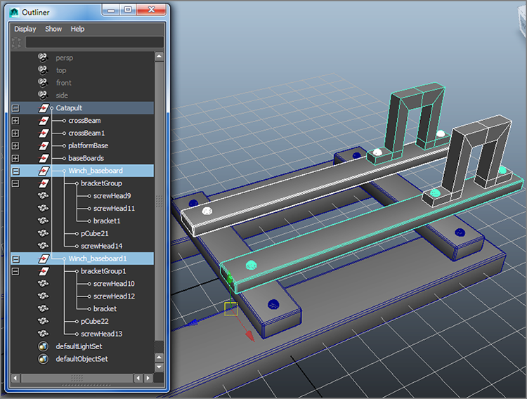
Figure 4-79: The winch’s base completed
The Ground Spikes
Figure 4-80: MMB+dragging the duplicated bracketGroup to another location in the Outliner removes the group from the Winch_baseboard1 group.
The last items you need for the base are the spikes that secure the base into the ground at the foot of the catapult. Follow these steps:
- Duplicate a bracket group and name it bracketGroupCOPY. Remove the group from its current hierarchy (the baseboard group) by MMB+dragging it to another location in the Outliner (see Figure 4-80). Center its pivot (Modify ⇒ Center Pivot).
- Move the bracket to the other side of the base. Rotate it on its side, scale it to about half its size in all three axes, and place it as shown in Figure 4-81 (left). Select the top vertices and move them closer to the base, as shown in Figure 4-81 (right).
- Now for the spike itself. Create a poly cube and position and scale it
to fit through the bracket. Scale the spike cube to about 3.5 in the
Y-axis. Select the bottom face of the spike cube and choose Edit Mesh ⇒ FACE ⇒ Extrude. Click the Thickness
helper and type in a Thickness of 0.5 and an
Offset of 0.15, as shown in Figure 4-82. Click in an empty
area to commit the extrusion. You can also use Modeling Toolkit to create the
extruded spike.

Figure 4-81: Position and scale the bracket assembly for the ground spikes (left). Move the vertices to reduce the depth (right).
Figure 4-82: Creating the spike
- Bevel the spike if you’d like. Then select spike and bracketGroupCOPY and group them together, calling the new group stakeGroup; center its pivot.
- Duplicate the stake group and move and rotate it 180 degrees in the
Y-axis to fit to the other side of the base. Organize everything
into a parent Catapult group (see Figure 4-83) and save your scene as a new version.

Figure 4-83: The completed base
The scene file catapult_v2.mb in the Catapult project from the companion
website has the completed base for comparison.
The Wheels
What’s a catapult if you can’t move it around to vanquish your enemies? So now, you will create the wheels. Follow these steps:
- First is the axle. Create a polygon cylinder (Create ⇒ Polygon Primitives ⇒ Cylinder) and then scale, rotate,
and place it as shown in Figure
4-84 to be the rear axle.

Figure 4-84: Place the rear axle.
Figure 4-85: Place brackets to hold the rear axle and adjust the vertices to make it fit.
- Duplicate one of the stake assembly’s bracket groups (bracketGroupCOPY) two times; then move and scale each of the two copies to hold the axle on either side. Move down the top vertices of the bracket to make the bracket fit snugly around the axle as needed, as in Figure 4-85. Remember to move the duplicated brackets out of their existing hierarchy in the stakeGroups. Group both the axle brackets together and name the group Axle_Brackets. You are not grouping the brackets with the axle cylinder. Keep them separate. You’ll organize the hierarchy better a little later.
- To make the axle a little more interesting, let’s add a taper at the ends. You will insert new edges around the ends by using Insert Edge Loop, which will be much faster than the Multi-Cut tool in this case. Select the rear axle cylinder and choose Mesh Tools ⇒ EDIT ⇒ Insert Edge Loop Tool. Your cursor turns into a triangle. Select one of the horizontal edges on the cylinder toward one end, as shown in Figure 4-86. A dashed line will appear running vertically around the cylinder. Drag the cursor to place the dashed line as shown in Figure 4-86 and release the mouse button to commit the new edges to that location. Repeat the procedure for the other side.
- Select the end cap faces and scale them down on each side of the axle
cylinder, as shown in Figure
4-87, to create tapered ends. Name the cylinder rearAxle. Now you’re ready for the rear wheels.
Figure 4-86: Insert an edge loop around the end of the cylinder.
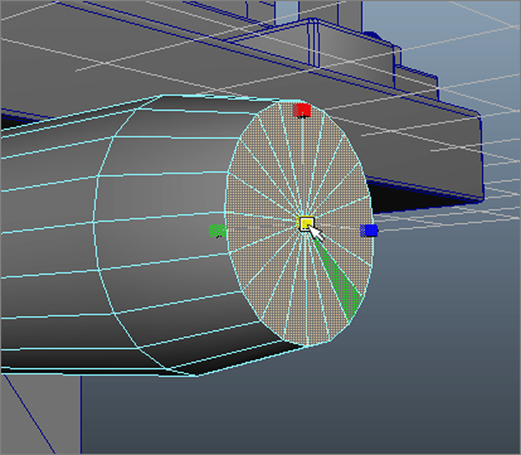
Figure 4-87: Taper the ends of the axle.
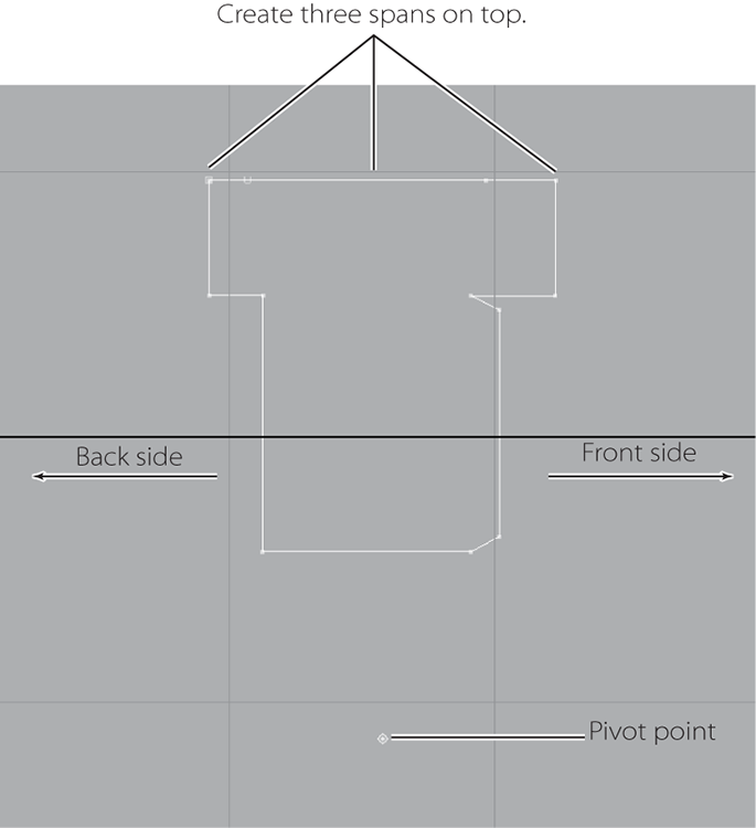
Figure 4-88: The profile curve for the wheel
- To model a wheel, first you’ll use NURBS curves to lay out a profile
to revolve. Go into the front view. Choose Create ⇒ CV Curve Tool
and select 1 Linear for Curve
Degree. Since the wheel’s profile will have no smooth curves, you can create a
linear CV curve like that in Figure
4-88. It’s important for the design to create three spans for the top
part of the curve. Place the pivot point (hold down the D key, or press Insert
on a PC or Home on a Mac) about 3/4 of a unit below the curve, as shown. This
curve will be the profile of the front of the wheel.
- Place the profile above the rear axle. To make sure the pivot point
for the profile lines up with the center of the axle, turn on Snap To Points
(a.k.a. Point Snap) () and press and hold down D to move the pivot. Snap the pivot to the center
of the axle, as shown in Figure
4-89. Turn off Point Snap.

Figure 4-89: The profile curve is in place for the rear wheel.
- Switch to the Surfaces menu set (Figure 4-90). Select the curve and revolve it by
choosing Surfaces ⇒ Revolve
. In the option box, set Axis
Preset to X to make it revolve correctly. Change Segments from the default 8 to
20 to give a smoother wheel. Set Output
Geometry to Polygons, and set Tessellation Method to Control Points. This will
create the edges of the faces along the CV points on the curve. Click Revolve,
and there it is (Figure 4-91).
Figure 4-90: Switch to the Surfaces menu set.
- Select the wheel object and bevel it. With the wheel still selected, delete the history and the original NURBS curve since you won’t need either again.
- Add some detail to the wheel. Duplicate a screw head and remove the
copy from whatever group it was in by MMB+dragging it out of the current group
in the Outliner. Arrange a few of the screw heads around the front face of the
wheel.
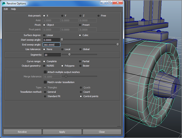
Figure 4-91: The wheel revolved
- Add a couple of braces on the front of the wheel above and below the
wheel’s middle hole with two thin, stretched, and beveled poly cubes, with
screws on either side (as shown in Figure 4-92). Again, make sure to remove the duplicated screw heads
from whatever group you got them from.
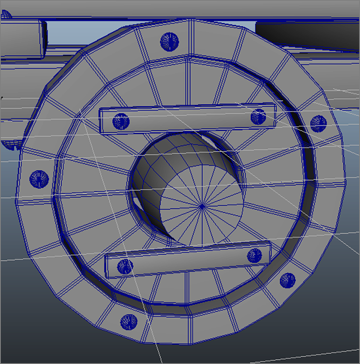
Figure 4-92: Adding detail to the wheel
- Select all the objects of the wheel, group them together by pressing Ctrl+G, and call the group wheel. Center the wheel group’s pivot point by choosing Modify ⇒ Center Pivot.
- Adding studs to the wheel makes for better traction when moving the
catapult through mud and also for a cooler-looking catapult. To create all the
studs at once, grab every other middle face along the outside of the wheel and
extrude them with a Thickness of -0.3 and an
Offset of 0.1, as shown in Figure 4-93. You can use
Modeling Toolkit Extrude instead to make the same extrusions if you prefer.
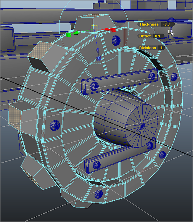
Figure 4-93: Extrude out studs for the wheel.
- Copy the wheel group and rotate it 180 degrees in the Y-axis to create the other rear wheel for the other side. Position it on the other side of the rear axle.
- Group the two wheels with the rear axle and call the new group node Rear_Wheel.
- Select the Rear_Wheel node and the Axle_Brackets group node, and duplicate them by choosing Edit ⇒ Duplicate or by pressing the hotkey Ctrl+D. Move the objects to the foot of the catapult for the front wheels. Rename the wheel group node Front_Wheel.
- Add the new axle bracket and wheel group nodes to the Catapult top
node by MMB+dragging them onto the Catapult node in the Outliner; save your
scene. Figure 4-94 shows the
positions and Outliner hierarchy of the wheels.
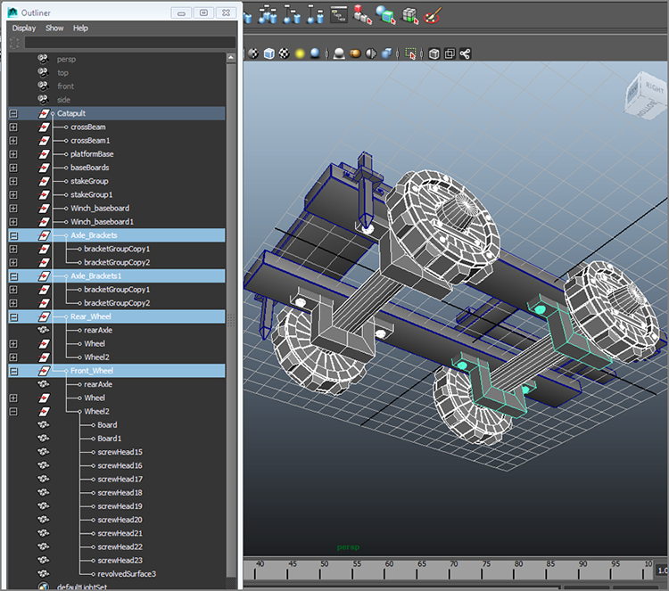
Figure 4-94: The wheels and brackets are positioned, and the hierarchy is organized.
The file catapult_v3.mb in the Catapult project from the companion
website reflects the finished wheels and base.
The Winch Assembly
To be able to pull the catapult arm down to cock it to fire a projectile, you’ll need the winch assembly to wind a rope that connects to the arm to wind it down into firing position. Since animating a rope can be a rather involved and advanced technique, the catapult will not actually be built with a rope. To build the winch assembly, follow these steps:
- The first part of the winch is the pulley around which the rope winds.
In the front view panel, create a profile curve for extrusion as you did with
the wheel that looks more or less like the profile curve in Figure 4-95. In this figure,
the first CV of the profile curve is on the left end of the curve. Place the
pivot point of the curve at that first CV. Revolve the curve around the
X-axis with only 12 segments (as opposed to the wheel’s 20). Center
its pivot, and you have the pulley.
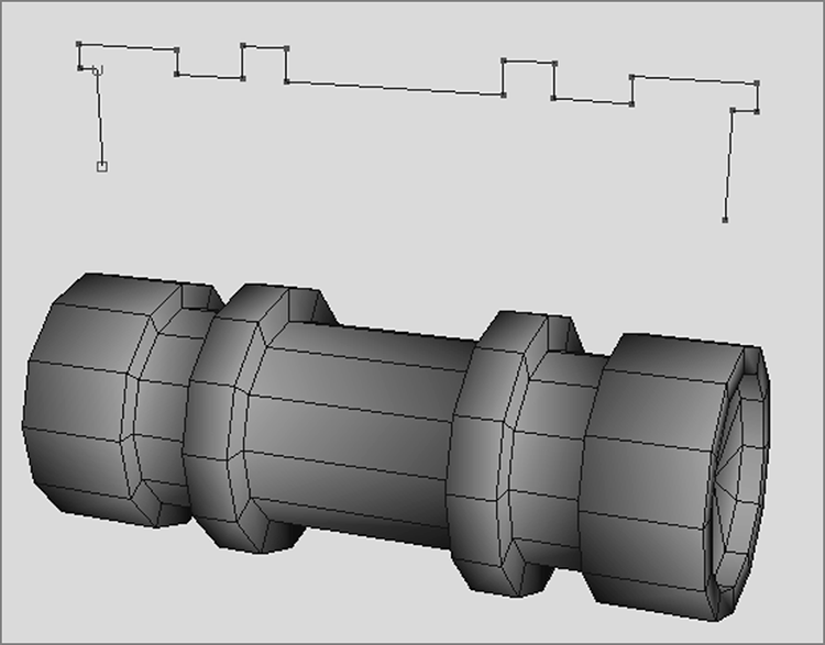
Figure 4-95: Create a profile curve and revolve it to create the object seen below the profile curve.
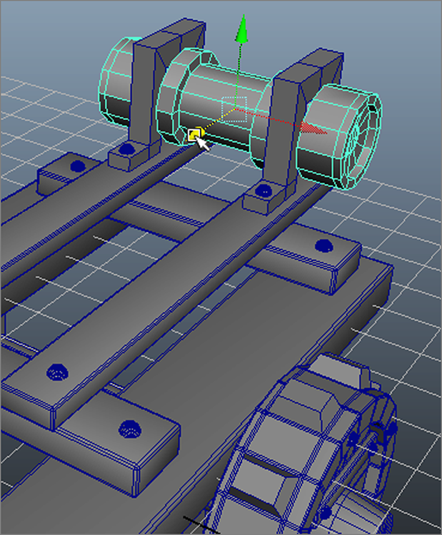
Figure 4-96: Place the pulley.
- Position the pulley at the rear of the catapult, placing the brackets in the grooves (see Figure 4-96).
- Now you’ll need some sort of geared wheel and handle to crank the pulley. Create a poly cylinder, and rotate it so it’s on its side like one of the wheels. Scale it to a squat disk with scale values of 1.4 in the X- and Z-axes and 0.4 in the Y-axis. Select the disk and bevel it.
- Off on the side of your scene, create another poly cylinder, and
rotate it to its side as well. Scale it to be a long, thin stick. You’ll use
this as the first of eight gear teeth for the wheel. Position it at the top of
the wheel, as shown in Figure
4-97. Click the Snap To Points icon in the Status line () and snap the
pivot point (press D to move the pivot) to the center of the wheel. Turn off
Snap To Points.
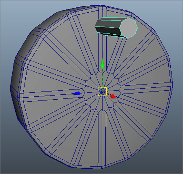
Figure 4-97: Making a gear wheel
- Instead of duplicating the gear tooth and positioning it seven more times,
you’ll use the array capabilities of the Duplicate Special tool. Select the
tooth and choose Edit ⇒ Duplicate
Special . In the option box, set
Rotate to 45 in the X-axis, and set
Number Of Copies to 7. Since the pivot for the
tooth is at the center of the wheel, as soon as you click the Duplicate Special
button, Maya places seven copies around the wheel at 45-degree intervals (Figure 4-98).
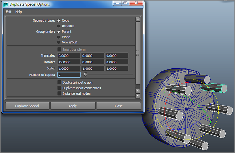
Figure 4-98: Eight gear teeth in place
- Now for the handle. Create a poly cube with enough segments for you to
adjust vertices and faces to match the handle shown in Figure 4-99. Create cylinders for the crank axle and
handle and place them as shown. Group all the parts together and snap the pivot
point to the center of the gear wheel disk. Name the group handle. You can bevel the handle if you want.
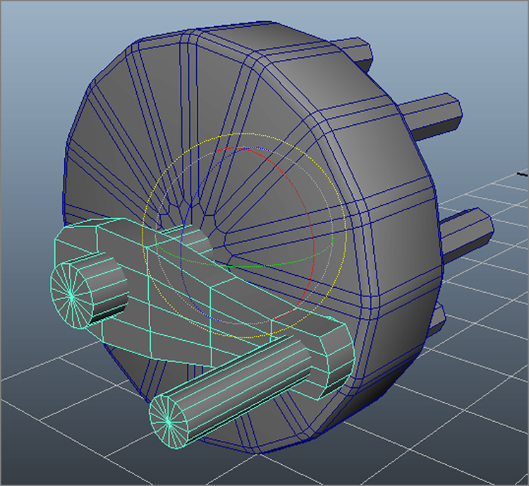
Figure 4-99: Use two cylinders and a poly cube to create the handle shapes.
- Group the geometry together, call the object Turn_Wheel, and center its pivot. Place it at the end of the pulley.
Place a copy (rotated 180 degrees) on the other side of the pulley. Figure 4-100 shows the
placement.
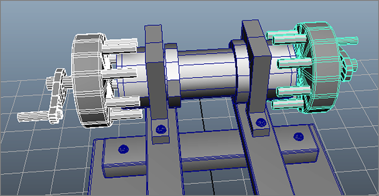
Figure 4-100: Place the turn wheels.
- Now you’ll need gear teeth on the pulley cylinder shape. Create a poly cylinder to be a long, thin tube like the gear teeth, and position it at the end of the pulley. Place it so that it is in between two of the turning wheel gear teeth. Place the pivot at the center of the pulley using Snap To Points.
- Duplicate the new tooth seven times around the pulley at 45-degree intervals with Duplicate Special.
- Make a
copy of each of those eight teeth and move the copies to the other side of the
pulley for the other gear. Group the pulley and turning wheels together, and
name the object Winch, as shown in Figure 4-101. Center the
pivot.
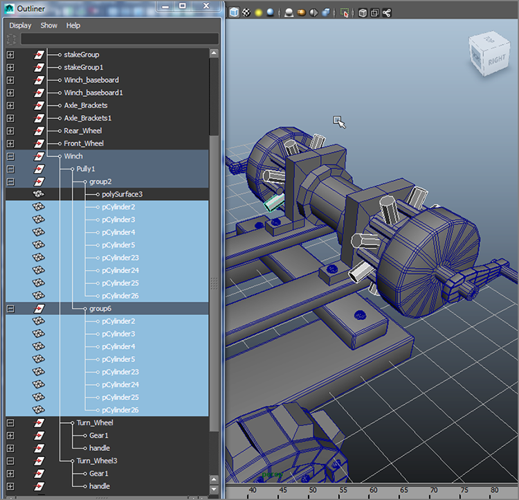
Figure 4-101: The winch gears and handles
- Using a couple of poly cubes that you shape by moving vertices, make a winch arm on either side to brace the winch to the catapult. Bevel the shapes when you are happy with their shapes. Place the braces between the crank handle and the turning wheel on both sides, and bolt them to the catapult’s base, as shown in Figure 4-102. Group them and add them to the hierarchy as shown. Save your scene file.
To verify your work up to this point, compare it to catapult_v4.mb in
the Catapult project from the companion website.
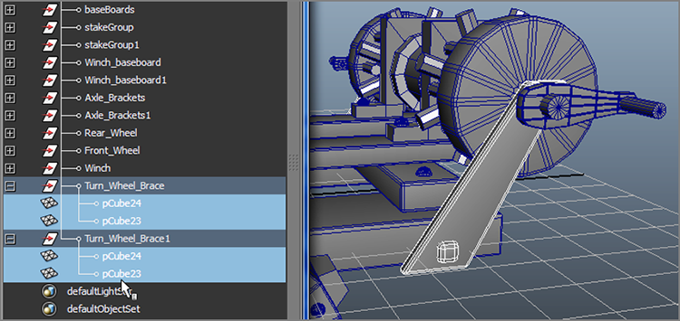
Figure 4-102: The assembled winch
The Arm
OK, now I’m kicking you out of the nest to fly on your own! Try creating the arm (see Figure 4-103), without step-by-step instruction, using all the techniques you’ve learned and the following hints and diagrams:
- Create the intricate-looking arm with face extrusions. That’s all you’ll need
for the arm geometry. Follow Figure 4-104 for subdivision positions to make the extrusions work
correctly.

Figure 4-103: The catapult arm assembly
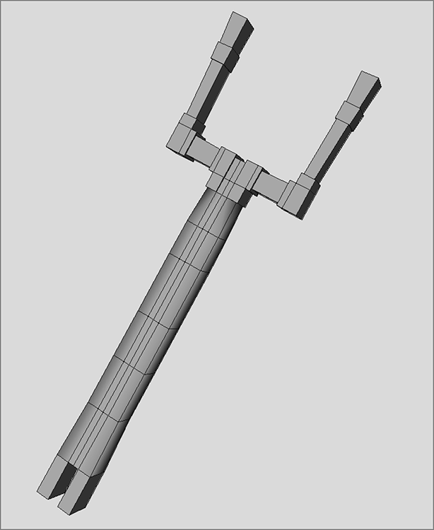
Figure 4-104: Follow the subdivisions on your model.
- Duplicate and place
screw heads around the basket assembly, as shown in Figure 4-105.
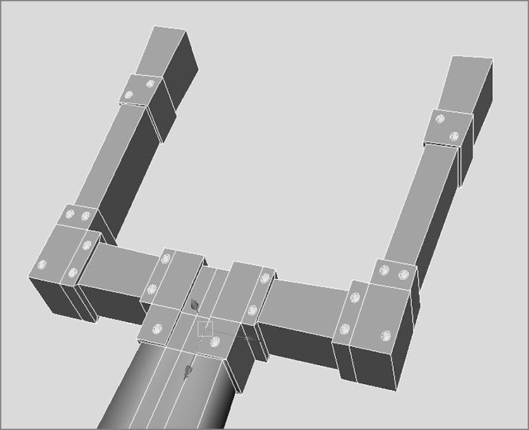
Figure 4-105: Place screw heads around the basket arms.
- Create the straps for the basket with poly cubes. It’s easier than it looks.
You’ll just need to create and extrude the cubes with enough subdivisions to
allow you to bend them to weave them together, as shown in Figure 4-106. The ends of the
straps wrap around the arm’s basket with extrusions.
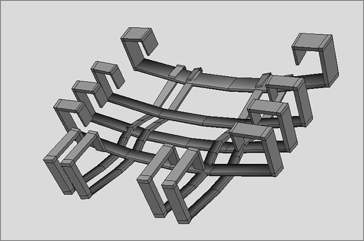
Figure 4-106: Basket straps
- Create the hinge for the arm with a couple of duplicated brackets and a cylinder.
- Create the arm’s stand with multiple extrusions from a cube. Follow the
subdivisions in Figure 4-107
for reference.
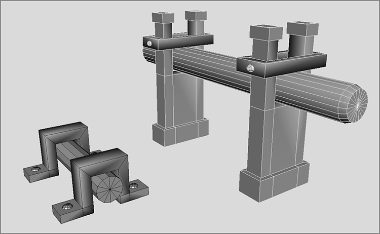
Figure 4-107: Follow the subdivisions on the arm stand.
- Bevel the parts you feel could use some nice edging, including the arm and stand pieces.
- Group the objects together and add their groups to the
Catapultnode.
When you’ve finished, save your scene file and compare it to
catapult_v5.mb in the Catapult project from the companion website.
Figure 4-108 shows the
finished catapult.

Figure 4-108: The completed catapult
Summary
In this chapter, you learned about the basic modeling workflows with Maya and Modeling Toolkit and how best to approach a model. This chapter dealt with polygon modeling and covered several polygon creation and editing tools, as well as several polygon subdivision tools. You put those tools to good use by building a cartoon hand and smoothing it out, as well as making a model of an old-fashioned catapult using traditional Maya workflows as well as new Modeling Toolkit workflows. The latter exercise stressed the importance of putting a model together step-by-step and understanding how elements join together to form a whole in a proper hierarchy. You’ll have a chance to make another model of that kind in Chapter 6, when you create a toy airplane that is used to light and render later in the book.
Complex models become much easier to create when you recognize how to deconstruct them into their base components. You can divide even simple objects into more easily managed segments from which you can create a model.
The art of modeling with polygons is like anything else in Maya: Your technique and workflow will improve with practice and time. It’s less important to know all the tricks of the trade than it is to know how to approach a model and fit it into a wireframe mesh.