PROJECT 6
Build Your Own Pinball Machine
THERE IS NOTHING MORE EVIL than a time burglar! A pinball machine is addicting to play and super fun to make. Evil geniuses don’t buy pinball kits with tons of fancy flippers, switches, and dials—so you are going to learn to make your own (see Figure 1-73). We will teach you the basics so that you can get started creating your own perfect pinball machine. In this ultimate finale to the “Gaming” section, you’ll hone your switch fabrication and woodworking skills and even dabble in 3D design.
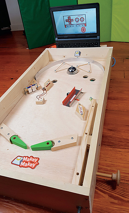
Figure 1-73 Finished pinball machine.
Cost: $$$–$$$$
Make time: 30 minutes
Skill level: 


Supplies

In this project, you can choose to construct a basic or more complex pinball machine. Both designs require a handsaw and miter box, coping saw, and drill. Almost all the materials are available at your local hardware store. There are even two different styles of pinball machines to choose from, one that allows the balls to drop through holes and roll to the front and another that holds them in place for scoring and is a simpler build. The accompanying Scratch game will be activated by a pull switch, and a laptop screen will function as the display board. As the ball triggers switches on the machine, sounds will play, and the player’s score will be calculated.
Step 1: Cut It Out
Many big-box hardware stores offer 24- by 48-inch pieces of plywood, and if you do not have a table saw, they will make a few cuts for you for a small charge. You will need to get someone to do your bidding and cut a piece of ½-inch plywood to the dimensions in the supplies list for the pinball machine you want to build. Complete the cuts listed on the list in Figure 1-74 for the simple pinball machine and the list in Figure 1-75 if you want to build a machine with a ball return. Many of the obstacles can be created with leftover scraps, so put those aside for now. Continue to step 2 to create the machine with a ball return, or skip to step 3 for the simple pinball machine. Note that it is also possible to use an old wooden drawer with a width of about 15 to 18 inches and adapt the instructions and measurements for the simple pinball machine model. This will require modifying some of the instructions and measurements, but if you want to do this, skip to step 4.

Figure 1-74 Cutlist for simple pinball machine.

Figure 1-75 Cutlist for pinball machine with ball return.
Step 2: Frame and Base Assembly for Pinball Machine with Ball Return
The 1- by 6-inch boards will create the sides, and the 1- by 2-inch board will create a base for the playing surface. For this assembly, it is important to keep in mind that a 1-inch-thick board is actually only ¾ inch thick.
On the 15-inch cuts of the 1- by 2-inch board, use a pencil and square to mark the holes in Figure 1-76. Place a cross in the center of the board at ¾ inch on each of these lines. Use a drill with a 1⁄8-inch bit to drill a hole through the board. On both of the 30-inch sides, mark at 2, 6½, 15, 21½, and 28 inches, and center the marks at ¾ inch. Continue using a 1⁄8-inch bit, drill the holes.

Figure 1-76 Marking holes for the base.
On the 8-foot 1- by 6-inch boards, draw a line 1½ inches away from each end. Use a square to draw the mark completely across the 6-inch side of the board. Align the 1- by 2-inch board on the edge of the 1- by 6-inch board between the marks you just made. Fasten them together with a clamp, or have a helper hold them in place. Use a small piece of tape on the drill bit to flag the 1-inch mark, as shown in Figure 1-77. Use the same holes you created earlier, and drill to a depth of 1 inch to create pilot holes in the 1- by 6-inch board. Drilling pilot holes will reduce the risk of the wood splitting and make assembly much faster. Unclamp the boards, and place a small bead of glue on the back of the 1- by 2-inch board. Then reposition and clamp it in place while inserting 1-inch No. 8 screws.
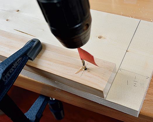
Figure 1-77 Drilling with flag.
To create the longer sides, align the 1- by 2-inch board with the side of the 1- by 6-inch board, and repeat the previous steps of drilling pilot holes, adding glue, and securing the 1- by 2-inch board in place with screws. Mark one of the long sides with an “L” for left side, and label the other side with an “R” for right side. Lay the left and right sides out with the 1- by 2-inch board facing the inside. Label the ends front and back. Next, we will create holes for the push rods that control the flippers to travel through. On the outer side of the 2- by 6-inch sides, measure and mark from the front 37⁄8 inches and 11⁄8 inches from the bottom, as shown in Figure 1-78. Use your drill to make a 17⁄64-inch hole at this location. It may be helpful to start with a 1⁄8-inch hole and work your way up to the correct size to avoid splintering.
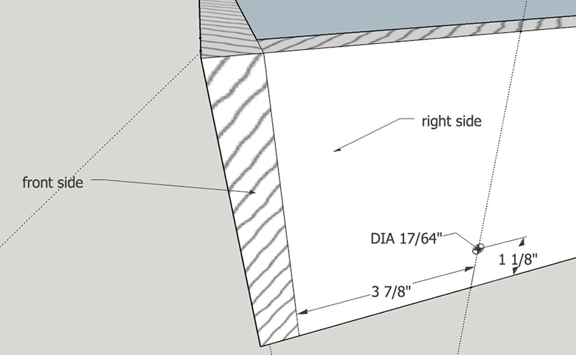
Figure 1-78 Holes for the pushrods.
It is time to drill some pilot holes so that we can place the pieces together to create a frame. Turn the 18-inch sides over so that the side with the 1- by 2-inch board is on the bottom. On the right side, draw a mark 3⁄8 inch away from the side at the top and bottom. Connect the line, and place crosses at 1, 2¾, and 4½ inches, as shown in Figure 1-79. Repeat the process on the left side. After all the marks are made, drill all the way through the wood with a 1⁄8-inch bit.
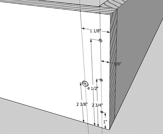
Figure 1-79 Assembly holes in 1- by 6-inch board.
On the front side, we need to create a hole with a 9⁄32-inch drill bit for the ball launcher in the lower-right corner. Center the hole 11⁄8 inches from the right side and 23⁄8 inches from the bottom, as shown in Figure 1-78. After all the pilot holes are drilled, use 1¼-inch No. 10 screws to assemble the base. Use a large carpenter’s square to make sure that the base box is square. Drop the plywood into the frame so that it rests on the 1- by 2-inch board. Use a 1⁄8-inch drill bit to create some pilot holes about every 6 inches around the perimeter of the base. Use some 1-inch No. 10 wood screws with tapered heads to secure the plywood to the base.
Step 3: Box Assembly for Simple Pinball Machine
Cut two 1- by 4-inch boards to 15 inches in length and two more to 25 inches in length. To create some pilot holes for assembly, mark the top of the 15-inch board on the right side ¾ inch from the top and bottom. Place a cross ¾ inch away from the right side. Repeat this step on the left side. You will need to create a hole with a 9⁄32-inch drill bit for the ball launcher in the lower-right corner. Measure in 11⁄8 inches from the right side and 3⁄8 inch high from the bottom of the 1- by 4-inch board, as shown in Figure 1-80.
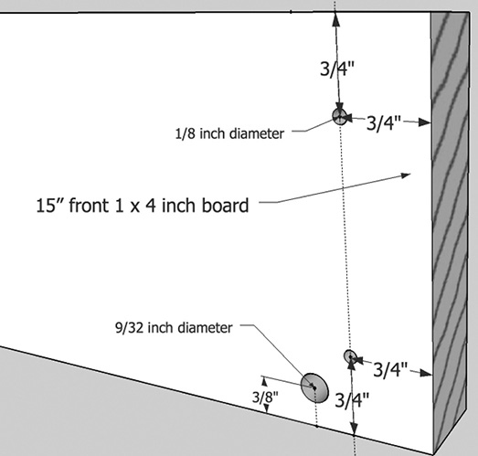
Figure 1-80 Simple pinball machine box holes.
Stand the boards on the ¾-inch side, and use a corner clamp or have a minion hold the 25-inch 1- by 4-inch board at a right angle to the top. With a 1⁄8-inch drill bit, drill through the wood at a 90-degree angle on these marks. Repeat these steps for the bottom side. Once the two boards are aligned, use the existing pilot holes to drill 1 inch into the longer piece. Secure the two pieces together by using four 1¼-inch No. 10 wood screws. Repeat this step to create the bottom of the box, excluding drilling the hole for the ball launcher.
Use a square to make sure that your box is aligned properly. If it isn’t perfect, that’s okay; just loosen the screws and adjust it by pushing on the sides. Leave the screws a little loose, and use the plywood base to help you square your box. Lay the plywood down on the box with the sanded side facing down. Create pilot holes around the edges about every 6 inches, and use 1-inch No. 8 wood screws to secure the plywood to the base (see Figure 1-81).
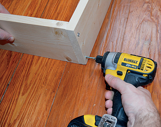
Figure 1-81 Simple pinball machine box assembly.
Step 4: Ball Launcher
You will need the 16 inch long piece of 1- by 2-inch board. Turn the 16-inch piece on its side, and secure it to a table using a clamp. Center marks at 2, 8, and 14 inches. Drill 1⁄8-inch pilot holes all the way though these pieces. Because we need the screw to sink into the wood further, use a piece of tape to make a flag on a 3⁄8-inch drill bit to mark ¾ inch, and drill to that depth. Position the 16-inch piece ¾ inch away from the wall, and drill 1⁄8-inch pilot holes into the plywood. Secure the piece in position with three 1¼-inch No. 10 screws.
Use a clamp to secure the 1½-inch piece to the table so that the cut side is facing up. Mark and drill a 17⁄64-inch hole 3⁄8 inch from the bottom, and centered at 3⁄8 inch from the sides. This piece will serve as a guide for the rod. We were able to purchase a 12-inch piece of ¼-inch steel rod from our local store, but if you have to buy a larger length, use a hacksaw to cut it to a 12-inch length.
To create your pull, you can use large wooden beads with a ¼-inch hole or drawer handles. Mark the center, and drill a ¼-inch hole at least ½ inch into the drawer handle. You may need to use a pair of pliers, a clamp, or a vise to hold the handle upright. Once the hole is drilled, use an epoxy glue to adhere the wooden handle to the metal rod. Once the glue is dry, slide a washer with a ¼-inch hole onto the rod and then a spring followed by another washer. Insert this into the hole, and slide another washer on, followed by a spring and then a set collar (see Figure 1-82). Push on the rod slightly so that the components are under slight tension, and then tighten the setscrew on the collar. Slide the 1½-inch wood guide onto the rod, and position and tighten a set collar on the end of the rod. Pull the rod back all the way, and mark the spot where the inner edge of the collar ends. This will be the spot where the collar will rest against the wooden guide. Secure the guide by placing a 1-inch No. 8 screw through the side of the machine. Once all the parts are tightened, place a ball in the chute and pull back or strike the rod with a quick blow. If your ball does not shoot out onto the playing surface, adjust and tighten any loose parts.
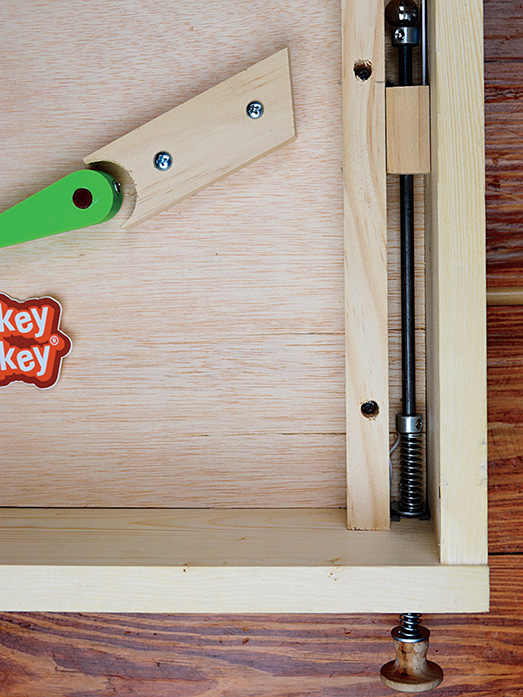
Figure 1-82 Ball launcher.
Step 5: Curve
To get the ball to curve around the playing field, you can use a thin piece of aluminum or cut circular shapes out of wood to direct the ball’s path. We used a 11⁄8-inch strip of aluminum that was about 1⁄8 inch thick. Slide the aluminum piece into the ball shooter chute, and gently bend it around the back end of the playing field. Slowly bend the strip around into the desired shape, as shown in the completed pinball machine in Figure 1-73. To hold the strip in place, either drill pilot holes and secure it with small tapered-head screws or with a pan-head screw placed just above the aluminum strip. By tightening the screw, the pan head should overlap the strip and hold it in place. If you drill holes to hold the strip in place, position them at least ¾ inch high to avoid knocking the ball off the path.
Step 6: Flippers
The flippers for this project can be 3D printed or made with some scrap 1- by 2-inch board. To create wooden flippers, mark a 1- by 2-inch board at 3 inches long. Place a washer or something with a 1-inch diameter so that it touches the bottom-right edge of the rectangle, and trace it. On the opposite end, place a washer with a ¾- to ½-inch diameter, and trace it. Connect the top line with a ruler. Mark the center of the larger 1-inch washer, and drill a 3⁄8-inch hole. Be sure to drill a pilot hole and work up to the correct size, keeping the drill at a 90-degree angle. Repeat the process, only this time place the larger washer on the left side. This will give you two very straight playing surfaces in case your scroll saw cutting is a little off. Clamp the piece to a work table, and cut it out using a scroll saw (see Figure 1-83). Use a file or rasp to remove any rough edges and even the cuts out. Finally, sand the flipper smooth. Attach a washer with a 3⁄8-inch hole to the bottom of the flipper using epoxy.
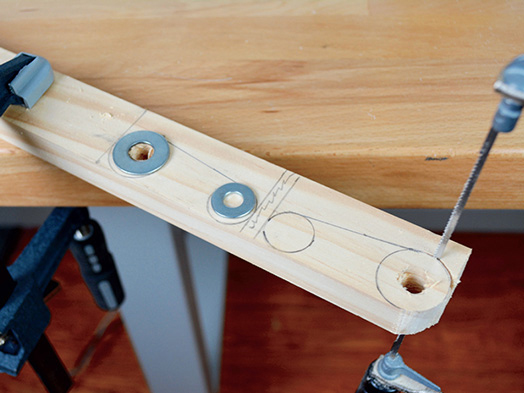
Figure 1-83 Wooden flipper.
To design flippers in Tinkercad, go to Tinkercad and sign in or create an account. Click the “Create a new design” button. Click the “Edit grid” button in the lower-right corner, and change the units to inches, confirming by clicking the “Update grid” button. Click and drag a cylinder to the work plane from the “Basics shapes” menu on the right. Its default size is 1 inch, and that is perfect for our needs. Click to select the cylinder, and the “Shape” menu will appear. On the “Shape” menu, drag the slider for number of sides over to select the maximum of 64 sides to make the cylinder as smooth as possible. Next, drag a cylinder hole shape from the “Basic shapes” menu; hole shapes are gray with diagonal stripes. Resize the hole shape to 3⁄8 inch diameter, and use the “Shape” menu to increase the sides to the maximum number. Position the hole roughly in the center of the cylinder, and then click and drag to select both shapes. Select the “Align” button icon, and several circles will appear. Click the circle in the front center and on the left center to align the hole in the center of the cylinder, as shown in Figure 1-84.
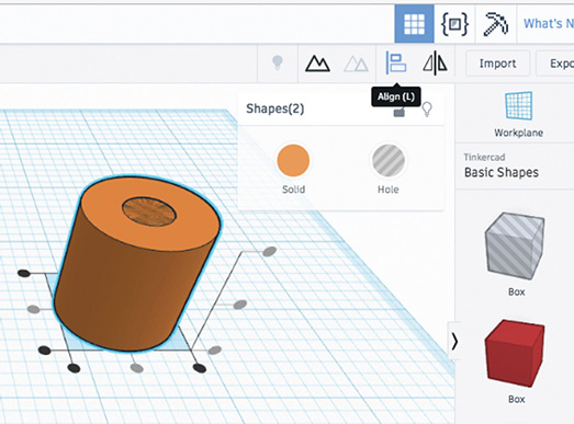
Figure 1-84 Hole alignment.
Click and drag a roof shape to the work plane. Click on the shape, and then left-click and hold the rotation arrows on the right of the shape to turn it 90 degrees so that the triangle is on top. Click and drag on the rotation arrow located in the front, and turn the rectangular base side of the roof 90 degrees toward the circle, as shown in Figure 1-85. Click on the shape, and use the black cone to raise the bottom to the surface of the work plane. Align the base of the roof shape with the center of the cylinder, and then click on the shape and change the length to 3¾ inches. Drag a “Hole cylinder” to the work plane, and resize it to 3⁄8 inch in diameter. This hole will be used to slice off the pointed end of the roof shape and will be replaced with a solid cylinder. Drag the shape over toward the end of the roof so that it touches both sides. Select all the shapes, and use the alignment tool to center the cylinder. To get this shape placed as accurately as possible, change the snap grid in the lower-left corner to 1⁄64 inch. Use the arrow keys to position the cylinder so that it touches both sides with only a small amount showing, as shown in Figure 1-86.
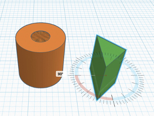
Figure 1-85 Roof rotation.

Figure 1-86 Position and alignment.
Click and drag to select all the shapes, and then click the “Group” icon. With the shape now split, drag a “Rectangular hole” to the work plane, and position it so that it covers the pointed end of the shape (see Figure 1-87). You may need to extend the hole to about 1½ inches so that it fully covers the shape. Drag and select both shapes, and click “Group.”
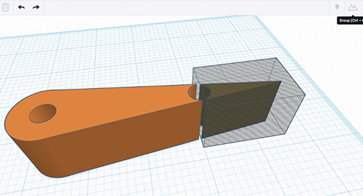
Figure 1-87 Erasing the pointed end.
To fill the void, drag a cylinder shape, and resize to a diameter of 1⁄8 inch. Place the shape in the space left by the hole, and then select both shapes and group them. Select the final shape, and drag the white box on top of it to set the height to ¾ inch. To create a hole for a set screw, drag a cylinder hole to the work plane and set it to a diameter of 1⁄8 inch. Rotate the cylinder 90 degrees so that it is parallel to the work plane. Use the black cone to set the height of the cylinder to 3⁄8 inch. Position the cylinder so that it is close to the center of the larger end and so that it goes into the main 3⁄8-inch hole. Use the alignment tool to center it, and then group the shapes to create the final design (see Figure 1-88). To get the file for the final design, click “Export,” select everything in design, and choose the file type for your 3D printer.
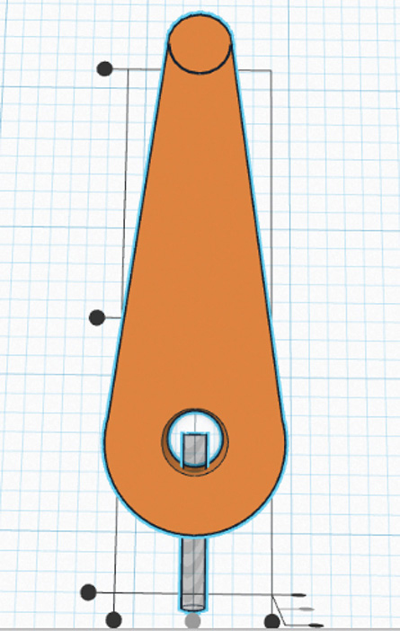
Figure 1-88 Placing the set screw hole.
Step 7: Actuators
There are hundreds of ways to build flippers and the mechanisms used to activate them. For both methods in this book, you will need two 4-inch pieces of 1- by 2-inch board. Center and drill a 3⁄8-inch hole ½ inch from the ends of both 4-inch pieces. Drill a set screw hole into the main hole with a 3⁄32-inch drill bit, as shown in Figure 1-89. Cut and place a 23⁄8-inch piece of 1⁄8-inch dowel through the hole. Insert and tighten a ¾-inch No. 6 screw to hold it in place. If you cannot find 3⁄8-inch dowel easily, most wooden hangers use 3⁄8-inch dowel for the pants portion of the hanger, which can easily be pried loose.

Figure 1-89 Actuator and dowel.
Step 8: Simple 1- by 2-Inch Push Stick Actuators
For the simple box, a 1- by 2-inch board and some scrap plywood can be used to construct the actuators. Start by drilling two 17⁄64-inch holes in the plywood floor 6 inches away from the bottom and 4¾ inches away from the outside edge. You will need to cut a 1- by 2-inch board into two 6½ inch pieces and four 2¾-inch pieces. Turn the pinball machine over, and measure and place a mark at 1 and 41⁄16 inches from the front on both sides. Draw a line to connecting the 1- and 41⁄16-inch marks. The 2¾-inch pieces will act as guides for the push stick to travel in between. Lightly coat one side of each block with wood glue, and align the blocks with the lines and the edge of the plywood, as shown in Figure 1-90. Use 1-inch brads to secure them in place. Cut two 2¾- by 4½-inch plywood rectangles. Lightly coat the tops of the 1- by 2-inch pieces you just fastened, and then nail the plywood in place over them to create the upper guide for the push rod, as shown in Figure 1-90. While the glue is drying, round off the corners of one of the 6½-inch pieces with a rasp or sandpaper. Sand both pieces heavily so that they will be slightly thinner than a normal 1- by 2-inch board and can slide easily in the guide. After sanding, wipe the push stick clean, and then rub paraffin or candle wax on all sides of it that will make contact with the guide. Slide the push stick in place with the curved end facing toward the center of the machine. Drill a pilot hole, and insert a ½-inch No. 8 screw partially to keep the stick from sliding out.

Figure 1-90 Push stick actuator.
To make the push sticks slide back after you push them, you will need to add a hook on the actuator that is attached to the flipper. Center a small hook about ½ inch from bottom edge of the actuator, as shown in Figure 1-90. Attach a hook to the inner edge of both 1- by 2-inch pieces that make up the sides of the guide. String a rubber band between the hooks, and experiment with different thicknesses of rubber bands until the push sticks move back into place after they are pressed.
Step 9: Rod Actuators
To make rod actuators, begin by flipping the pinball machine over and drilling the two holes for the flippers in the plywood floor. Make a mark 6 inches away from the front inner edge on both the right and left edges of the plywood floor. Connect the two with a mark to make a guideline and then place a cross at 4¾ inches from the inner-left side and 4 inches from the inner-right side.
To make guides, turn a section of 1- by 2-inch board on its side so that the ¾-inch side is visible, and secure it with a clamp or vice. Center a mark ¾ inch away from the end, and drill a 17⁄64-inch hole at a 90-degree angle through the board, as shown in Figure 1-91a. Remove the board from the clamp, and then cut it to a 2-inch length. Repeat the process to make a guide for the other side. Once you have cut the guides to size, you need to create two 1⁄8-inch pilot holes for screws to secure them to the plywood. Place the pilot holes about ½ inch from the opposite edge of the guide hole, as shown in Figure 1-91b. One of the rods will be shorter and need more space to travel, so it is necessary to cut a notch out of the guide. Orient one guide so that the screw holes are at the top, and use a small hand saw to remove a ¾-inch-square from the bottom-right corner, as shown in Figure 1-91b.

Figure 1-91a Drilling guide holes.

Figure 1-91b Pushrod actuators.
To create the push rods, cut the 3⁄8-inch rod to 6½ and 8½ inches. Mark a 3⁄8-inch drill bit at ½ inch with a tape flag, and drill out a hole in a drawer handle. These rods will take a beating, so use epoxy glue to secure them in the handle. When the handle and rods are dry, rub them down with some paraffin or candle wax and then place these rods into the holes on the side and then slide the guides on the ends. The guide also serves as a stop for the flippers, and its position is important. Tighten the screw on the actuator, and push the flipper onto the rod. Check the movement of the flipper when you press the rod in and note where the actuator stops when the push rod is pushed out about 2 inches. Use the set screws on the flipper or actuator to adjust the swing to your liking. When you have the movement you desire, tighten the set screw, and use 1-inch wood screws to secure the guide to the base.
To get the flippers to push back out, add a hook on both of the 4-inch actuators, as shown in Figure 1-91b. It should be centered ¾ inch on the opposite end from the rod. Place hooks on the inside wall about ¾ inch down and 2½ inches from the inside front wall. Try stringing different types of rubber bands until you get a quick return without too much tension. To keep the pushrods from flying out of the machine, place a rubber band around the rod next to the wall where the rod sits when it is at rest.
Step 10: Legs and Laptop Holder
There is a perfect playing speed and angle to achieve the perfect play on your pinball machine. We recommend that you stack some scrap blocks under the back of the machine and test it out until you find the perfect angle. Once you find the perfect angle, measure from the floor to the top of the back of your machine, and cut two 1- by 2-inch boards that length. For the machine with a ball return, you will need two 9-inch lengths, and for the basic model, they will be 8 inches. Attach them to the back with two 1¼-inch No. 10 screws, placing them ½ to 1½ inches from the sides. Before placing the legs, you might want to decide whether you want to use a small laptop as a display. In our build, we added a 15-inch 1- by 2-inch board across the top of the legs. This creates a slot, as shown in Figure 1-92, to place a 13-inch laptop when it is fully open. You can use a small 4-inch piece of scrap wood screwed into the bottom or backside to hold the laptop at the ideal height. Before setting the height, keep in mind where you need to plug in the power supply and USB cables for the laptop. We are using an older laptop for our machine, but if you are using a newer unit, we recommend that you place a small sheet of plexiglas in front of the laptop to protect the screen. Be sure to drill holes in the plexiglas before attaching it with screws.

Figure 1-92 Legs and laptop.
Step 11: Bumpers, Guides, and Obstacles
Take time to knock the ball around the machine when you get your flippers installed. Cut a few 1- by 2-inch scraps, and use them as temporary guides on the sides of the flippers. If you have access to a hole saw, try drilling a hole in the 1- by 2-inch piece and then cutting it in the center so that you have a scrap that you can fit snugly up to the flipper, as shown in Figure 1-93. Mark and cut the angles that work best for you. If you don’t have a lot of scrap wood, another option is to use rubber bands and screws with nylon spacers. For our build, we used 1-inch screws inserted into 5⁄8-inch-tall nylon spacers to create some bumpers. You can string some wide rubber bands to create bumpers that guide the ball to the bell, as shown in Figure 1-94a.
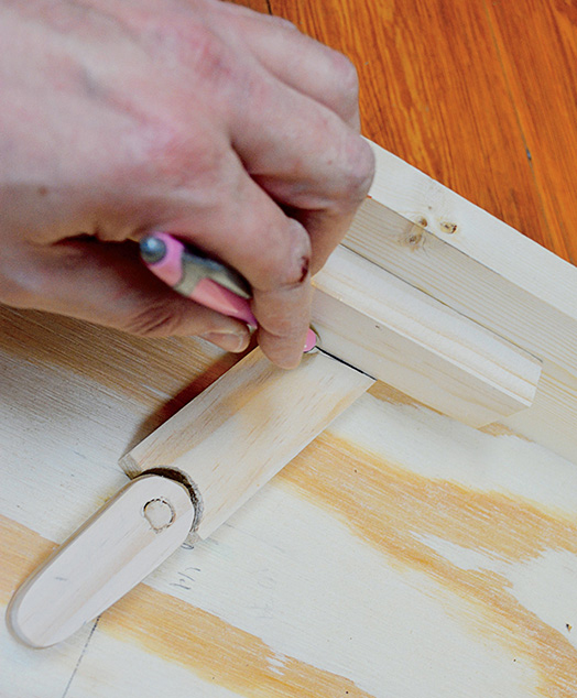
Figure 1-93 Guides.

Figure 1-94 (a) Rubber band bumpers. (b) Wiring harness.
Step 12: Wiring and Scratch Link
Since there are so many switches that need hookup wire, an old ethernet cable makes a great wiring harness. Cut the end off, measure about 10 inches from the end, and use a box cutter to splice the outer covering. Untwist the wires, and you find some pairs of color-coded wires. What is great about these cables is that each color pair has a striped and solid wire. Decide whether you want striped or solid to be EARTH, and you can save yourself a lot of confusion later. In the description of most of the switches, we simply told you to run a wire to EARTH or key press. You will have to define which one of the keys you want to wire it to and which sounds you want to trigger in your Scratch game. In the builds shown, the wiring harness was routed out the top of the game. For the ball return model, you will need to drill a hole for the wiring harness to exit near the top (see Figure 1-94b). You can check out the code for our game on our webpage.
Step 13: Launcher Switch
The ball launcher is the perfect location for a switch because of the metal rod (see Figure 1-95). We will create our EARTH by drilling a small hole through the bottom corner where the rod enters the machine. Loosen the set screw on both collars, and move the spring and washer away. Strip the end of the wire, and slide it through the hole. Make a loop at the end of the wire, and then attach it to the wood with conductive tape around where the washer rests. Replace the washer, and make sure that the spring has a slight bit of tension; then tighten the set screw. We will use the collar at the end of the rod to act as contact point against the wood guide. Drill a hole in front of the bracket, and place the wire through. Secure the wire to the bracket with conductive tape where the collar contacts the wood guide. Route one wire to EARTH and the other to the key press of your choice on Makey Makey.

Figure 1-95 Ball launcher.
Step 14: Ball Return Switches
Cut a length of 1- by 2-inch wood 17¾ inches long with 60- and 120-degree angles on the ends. With the ¾-inch side up, drill three 1⁄8-inch pilot holes, one in the center and the others 2 inches from the end. Follow up with a ¼-inch bit to a depth of 1 inch. Flip the machine over, and place the length of wood so that the lowest edge is about 8 inches from the inner edge of the front. Secure it in place with 1-inch screws. Next, use a ruler to mark where the ball will exit the side of the machine. On the outside edge, mark down 1¾ inches, which will be the top of the hole. Use a large drill bit to drill a hole at the same angle as that of the 1- by 2-inch piece we just installed as close to the plywood as possible. With a hand saw, cut straight down to match the angle of exit (see Figure 1-96).
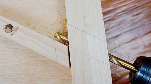
Figure 1-96 Drilling and cutting the ball exit.
We recommend that before placing your holes you play your machine for a while and keep track of the spots that are somewhat difficult to hit. The holes we are creating will become “skill shots.” Mark the spots, and make sure that they are above the angled 1- by 2-inch piece on the back of the board. Use a 1-inch hole saw, auger, or paddle bit to make holes at those locations. With the holes drilled, use the remaining scraps of plywood to cover the back of the machine. Secure the back in place with 1-inch screws after you complete the switches for each hole. For the switches, you have several options, but one thing to keep in mind is that the ball needs to move toward the bottom of the machine after the switch is triggered. A set of simple pressure switches that are taped to the back cover and are triggered when the ball falls through the hole will suffice (see Figure 1-97a). The wires were routed to the top of the machine and covered with tape so that the ball would easily roll over them. Be sure to test your switches as in Figure 1-97b before screwing down the back cover!

Figure 1-97 (a) Pressure switch construction. (b) Wire routing and testing.
Step 15: Bell Switch
If you have a metal bell and a metal ball, you might be pondering whether you have the beginnings of an awesome switch. Why couldn’t you just place some conductive tape next to the bell so that when the ball hits the bell, it completes a circuit? In theory, it should work right? Actually, if you were to hold the ball there, it would work, but if you try it with a quickly moving ball, the situation is much different. Only a very small portion of the ball is making contact with the tape, and since the ball is moving very quickly, it might not trigger a connection with your Makey Makey. The Makey Makey might register this as an error in the sampling rate because the contact time and surface area just aren’t big enough. To fix this problem, like all evil geniuses, we cheated. We planned where we wanted the bell, traced around it, and then positioned a roller switch just inside and behind the bell. So when the ball hits the bell, it will ding and also trigger the roller switch. This supersensitive switch is triggered by a very small amount of movement and gives Makey Makey a nice strong connection to trigger a key press during the sampling rate. To wire the switch, you’ll connect a ground wire to pin 1 and your key press wire to pin 2 (see Figure 1-98). (You can also wire this switch so that it is always triggering a key press on your Makey Makey if you want to institute some kind of evil timer. Just saying .…)
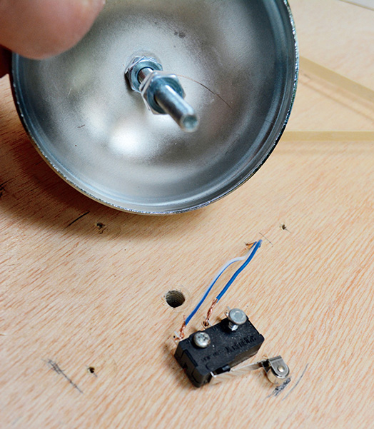
Figure 1-98 Bell switch wiring.
Step 16: Rail Track Switch
You know how we just discussed how a metal ball and two conductive surfaces do not make the best switches. It’s still true, however, that there are some things that you can do to make it work. One of those is slowing the ball down or extending the surface area with which it makes contact. So you will want to add some curves to your track and ensure thast the ball is making contact with both sides. You can use solid copper or steel wire to make a track (see Figure 1-99). Wire from clothes hangers works great, but you will need to lightly sand it to remove the coating. Our rail track is just under 8 inches long, so no cross ties are needed to hold it together. The start of the track needs to be in a place where the ball can be hit hard enough to roll up the rails or in a place where the ball can be guided into the rail while coming back down. We opted for the end of the curve because the ball has a good deal of speed from the ball launcher. To start, drill two 1⁄8-inch holes in the plywood floor about a ½ inch apart to create the starting point. Place about 1 inch of the wire through, and bend the ends over on the bottom. You will need to form the wire so that the gap is about 3⁄8 to ¼ inch. You can make the track twist or turn however you desire, but remember that the point is to slow the ball down so that the Makey Makey will register a complete circuit. Drill two 1⁄8-inch holes about 3⁄8 inch apart into a small scrap of 1- by 2-inch wood for the bottom of the ramp. Place a pilot hole through the scrap, and once you have it positioned where you would like, secure it with a 1-inch screw. On the backside of the machine, connect one wire to EARTH and the other to a key press on the Makey Makey.

Figure 1-99 Rail track and ball switch.
Step 17: Swing Switch
This simple switch is made with cardstock or cardboard flag coated in foil that swings back and touches a strip of conductive tape to complete a circuit when the ball strikes it (see Figure 1-100). Start by making some small rectangles out of cardboard. Bend some wire at about 2 inches to make an L shape to form one of the posts for the swing frame. You might want to add a slight bend to the end of the wire that will become the crossbeam. This will keep the flags from sliding into the pole. Cut some cardboard flags about ¾ inch wide and 1¼ inches tall. Use heavy-duty aluminum foil, and cut a foil strip the same width as the cardboard flag. Adhere the aluminum with double-stick tape to one side of the cardboard rectangle. Place the flag next to the wire, and fold the aluminum foil loosely over it and use some double-stick tape to adhere it to the other side. Because the foil is relatively thin, use some tape to reinforce the top of the swing. We placed some beads between our flags as spacers to keep them from interfering with each other. When you have placed all the flags onto the wire, bend the leg down and snap it off at 2 inches. Position the swing about ¼ inch near a wall or obstacle. Mark the position of the legs, and drill 3⁄8-inch holes through the wood. Place the wire through the holes, and bend the ends over. Place a strip of tape on the wall where the swings will contact the wall. Drill a hole, and place a wire through it; then attach it to the tape. Run this wire to a key press on the Makey Makey. Connect a wire to the swing frame and route this wire to EARTH on Makey Makey.

Figure 1-100 Swings with aluminum.
Step 18: Basket of Nails
Vintage pinball machines often use baskets created by brads that are partially hammered to form V shapes for scoring. To create one of these, draw a V or U shape on your pinball floor. Place the brads about 1⁄8 inch apart, and hammer them in so that only about a half-inch of them remains above the floor. Flip the machine over, and wrap a wire around the bottom brad and bend it over. Strip a long section of wire, and wrap it around the two brads to the right and left of the center brad. Bend the rest of the brads back, and run one wire to EARTH and another wire to a key press on the Makey Makey. When the ball comes to rest at the bottom of the V shape, it will complete the circuit. It’s important to note that from that point on, the circuit will be complete, and your computer will think that your are constantly pressing that key (see Figures 1-101 and 1-102).

Figure 1-101 Nail basket.

Figure 1-102 Wiring the V.
Step 19: Teeter-Totter Channel Switch
This switch uses a U-shaped channel made from sheet metal or posterboard that tilts on a straw. When the channel tilts, the metal channel or conductive tape touches a strip of conductive tape or fabric on the playing surface of the machine completing a circuit. Begin by making a channel out of thin cardboard or metal. If you are using sheet metal, be sure to add some tape to the sharp edges. If you use poster board later, you will coat the end with conductive tape where the channel will make contact with the playing surface. Cut a skewer ½ inch longer than the width of the channel. Use a hot-glue gun to place it almost on the center perpendicular to the channel with the skewer hanging about ¼ inch over each side. Due to the imbalance, one side will naturally rest on the playing surface; you will want that side to face the front of the machine. Speed is everything in the success of the switch, and you want the ball to be traveling at just enough speed to tilt the channel. Try moving the channel around to see where the best placement will be. When you have found the best place, mark the bottom edge and the position of the skewers. Drill a small hole just off to the side by the center of the channel and place some hookup wire through it. Strip the end of the wire, and attach it to the channel with conductive tape, as shown in Figure 1-103. If you are using poster board, run a line of tape over the wire and then to the end of the channel. Coat the end and edge with conductive tape. Put the channel back in place using the marks you made earlier, and tilt the far end down. Place some guide marks where the channel meets the playing surface when it is tilted. Just off to the side of these marks, drill a small hole and run hookup wire through it. Place conductive tape over the wire, and make a contact pad in this area (see Figure 1-104). Return the channel to position, slide a ¼-inch piece of straw over each end, and glue them in place, being careful to avoid getting glue on the skewer.
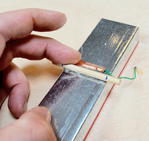
Figure 1-103 Wiring the channel.
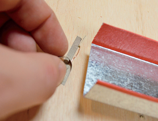
Figure 1-104 Wiring the contact pad.
Taking It Further
There are tons more possibilities for making switches on your pinball machine. Think about how you could create a Scratch game for scoring or use action figures to create a theme!