PROJECT 9
Makey Makey Etch-a-Processing Sketch
Remember how much the minions used to love playing with your Etch-a-Sketch? What if you could create a new one with a simple Processing program and a Makey Makey? Find a red box, some milk lids, and let’s get started. If you haven’t used Processing before, it is a really cool programming language for making interactive digital art. To create our own Etch-a-Processing Sketch, we only have to write a few lines of code that will track our mouse movement (see Figure 2-20).

Figure 2-20 Makey Makey Etch-a-Processing Sketch
Cost: $
Make time: 30 minutes
Skill level: 

Supplies

Write a Sketch in Processing
Step 1: Look Around Processing
Download the Processing IDE from https://processing.org/. Create a new sketch, and let’s take a moment to look around at the Processing environment. It’s pretty straightforward. You have your sketch window, a “Play” button that will run your code (which will run your sketch in a new window), and a “Stop” button. If you are new to this type of programming, I’ve included comments for every line to explain how the sketch works. You do not need to include the comments in your own sketch. However, commenting also helps you to debug when things go wrong. “//” is used to note a comment, so that a computer will not read the comment as a line of code. Instead, the computer will skip anything after “//” and read the next line.
Step 2: void setup()
Everything you write in void setup() will run only once when you start the sketch. Inside the parentheses we will set the size of our screen area and then tinker with color areas so that you can see how to change the sketch if you get another idea you want to try.
Let’s set the size of the screen area and background color type. The setup function will run everything inside the brackets once at the start of the sketch. Remember to include semicolons at the end of each line of code.
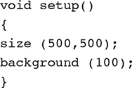
Now click the “Play” button to run your sketch. A gray square should appear. Now, to make our Etch-a-Processing Sketch window, change the size and add a frame rate so that the frame rate will refresh when you are drawing, allowing you to track mouse movement from frame to frame. To resemble an Etch-a-Sketch, we want to set the background to white by setting the color code to 255.
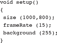
Step 3: void draw()
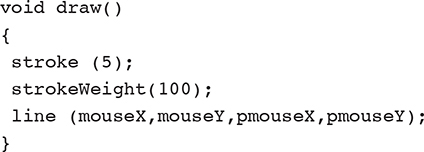
To track mouse movements, we only need four more lines of code. The void draw() function will continually run the lines of code between the brackets until the sketch is stopped. You must use this function to track the movement of the mouse while the sketch is open. You will set your stroke by typing “stroke” and include the color for your stroke in the (). For tinkering purposes, let’s try “5” inside the parenthesis. If you run the sketch like this, nothing will happen because we haven’t tracked our mouse movement yet.

Step 4: Track Mouse Movement
We not only want to track our mouse movement, but we also want to draw a line between the mouse’s previous x,y location and the current x,y location so that our sketch will resemble the function of an Etch-a-Sketch. To do this, we will use line() because it allows us to draw a line between two paths. Inside the parentheses (mouseX, mouseY) will find the current location of the mouse, and (pmouseX, pmouseY) will draw a line from the current location to the previous location of the mouse from the previous frame.

Try changing the stroke color to the number 240. What happens? We want to make our line look more like the gray color of an Etch-a-Sketch, so we will set our stroke color to 120.
Step 5: Test
Your Processing sketch should now resemble Figure 2-21 without the comments. It’s time to test your sketch and begin drawing with your mouse in the “Sketch” window (see Figure 2-22).

Figure 2-21 Processing sketch with comments.
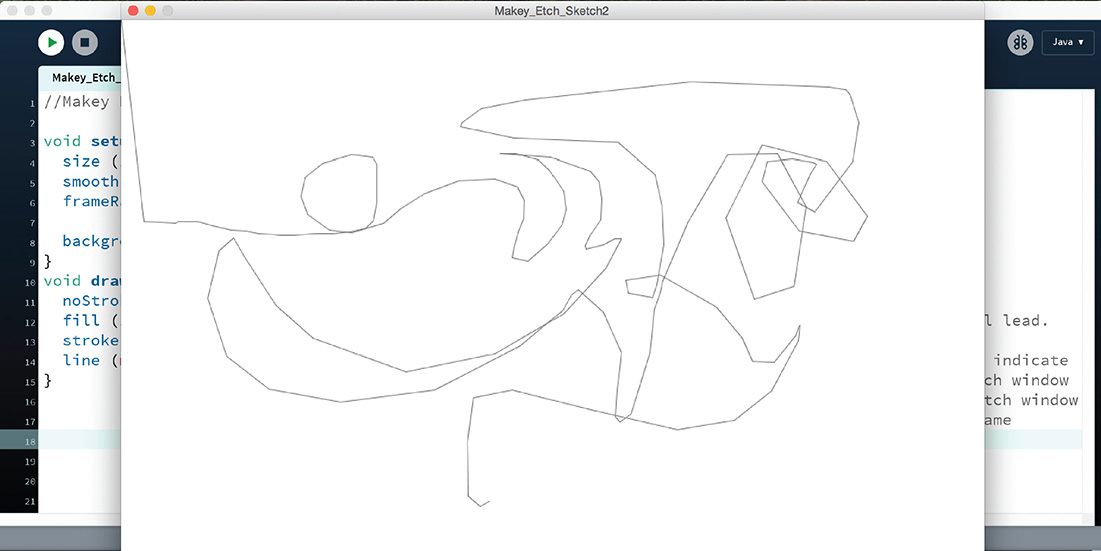
Figure 2-22 Testing mouse drawing in “Sketch” window.
Step 6: Tinker with strokeWeight()
You might be wondering how to change the size of your drawing line. The stroke function defaults to a width of 1 pixel, and if you want to change it, you’ll have to add strokeWeight(). Try adding strokeWeight (100) to your sketch. Once you are happy with the size of your drawing pencil, it’s time to make your box and hook up your Makey Makey.
Make an Etch-a-Sketch Box
Step 1: Prepare Box and Drill Holes
With the lids on the box, decide the best placement. For this build, we centered the lids 2 inches from the side and 1½ inches from the bottom. Mark the bottom and side of the lid, and align it with those marks. Use a pencil to lightly trace around the lid, as shown in Figure 2-23. Measure up from the bottom of the box to where the center of the lid is located, and place a mark at the center and at the same distance from the bottom on both sides. It’s a good idea to draw a line across the center.
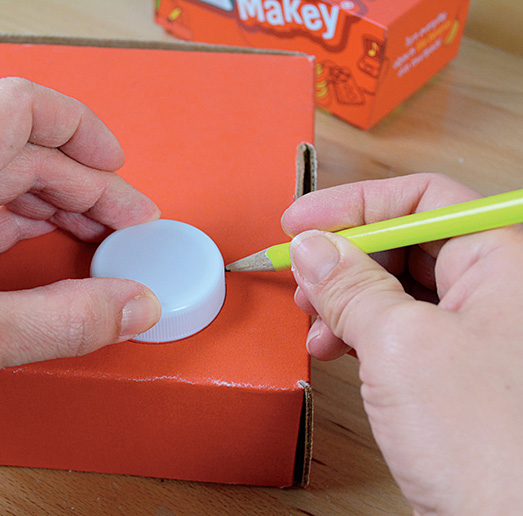
Figure 2-23 Trace around the lids.
The lids will become the dials used to control our sketch machine, but we don’t want them to rotate all the way around because that would twist the wires too much. To achieve this, we are going to place some stop screws just below the center that will also act as connections for our directional controls. Measure in about 1⁄8 inch from the side, just below the center, and turn the screw over so that the head is resting against the box. Trace around the head as shown in Figure 2-24, and then mark the center. Repeat this step for the other side. Use a drill, craft knife, or pencil to make a hole for the screw. Also place a hole in the center of the circle for the screw on which the dial will rotate.

Figure 2-24 Determine screw placement.
Step 2: Prepare the Box with Conductive Paint
Use the Bare Conductive paint to make larger contacts areas for the dials. Be sure to paint the area around where the screw will poke through the cardboard so that it will make contact. Leave at least a ½-inch space in the middle so that when the dial is centered, it will not make contact with either connection and will act as a stopping point for sketching (see Figure 2-25). Place the box aside and allow the paint to fully dry.
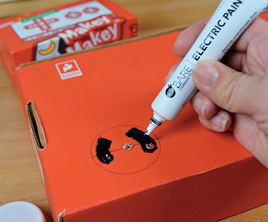
Figure 2-25 Bare Conductive paint pen.
Once the paint is dry, slide a flat washer onto a 1-inch screw, and place it into the holes you drilled for stop screws. You can see the stop screws and flat washers in Figure 2-26. Notice that the flat washer makes contact with the Bare Conductive paint. On the opposite side place another washer, and then fasten a nut firmly to the screw. Repeat this step for the other three holes.

Figure 2-26 Screw placement and preparation of controller lids.
Step 3: Transform Lids into Controllers
Use a clamp or a pair of pliers to hold a plastic lid, and drill a 5⁄32-inch hole in the center of the lid. This hole will connect the controller to the box and also function as the EARTH input. Now turn the lid on its side and drill a 2⁄32-inch hole near its bottom edge. Later we will insert a set screw here to constrict the movement of the controller.
On the inside of the lid, run a piece of conductive fabric tape from the hole in the center across the lid, up the side, and over the hole that you drilled for the stop screw. Run the tape up the outside wall and back to the hole in the center of the top, as shown in Figure 2-26. Place a 1½-inch pan head screw into the hole, and place a spacer on the bottom side. Turn a ½-inch No. 4 screw into the hole on the side, piercing through the tape (see Figure 2-27). Be careful not to twist the tape around the screw. You can ensure that the screw goes through the tape by holding the tape with a fingernail as you turn the screw through the tape. Cut a 1½-inch piece of conductive tape, wrap it around the No. 4 set screw, and then extend it about ¼ inch over the edge of the lid. Fold the tape over, and stick it to itself back down to the set screw to create a flexible brush, as shown in Figure 2-27. This will extend your EARTH connection and brush across the conductive paint inputs on the box. Before securing the controllers to the box, insert the screw into the center hole you drilled and observe whether the brush is making a connection with the conductive paint, as shown in Figure 2-28. If it does not, you may need to make the conductive tape brush longer. Also check to see that the brush does not touch either side of the conductive paint while the dial is centered. If so, shorten the length of the tape brush or you will not have very good sketching control.

Figure 2-27 Lids as EARTH brush.
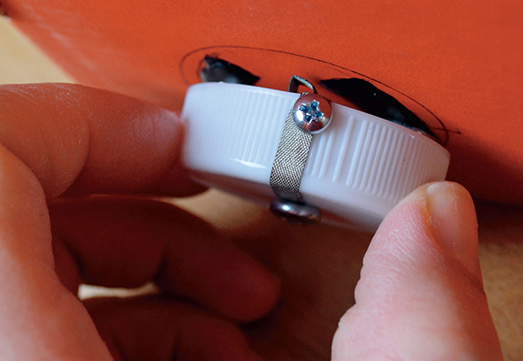
Figure 2-28 Making connections.
Step 4: Attach the Lids to the Box
Once you have made any necessary adjustments, place the controller back through the hole, and center your conductive tape brush so that it is not touching either conductive paint input. On the inside of the box, slip on a washer and fasten a nut on the screw, but leave the screw so that it is still turnable. We are going to lock the position of the nut in place with a second nut. This will allow the dial to turn but not come loose. With a pair of needle-nose pliers, hold the first nut firmly in place, and use a second pair of pliers to tighten the second nut as much as possible, as shown in Figure 2-29. You should be able to move the dial left to right, noting that when the set screw touches the stop screw, the dial’s rotation is limited.
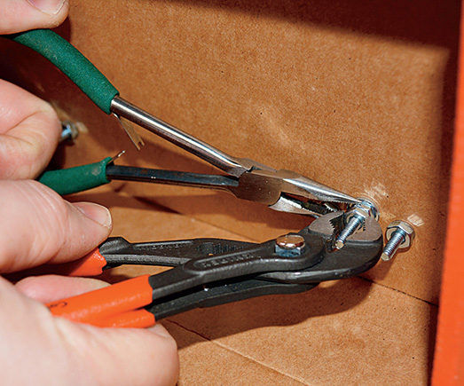
Figure 2-29 Attaching the lids from the inside.
Step 5: Hook Up Your Makey Makey and Play!
Now you are ready to hook up your Makey Makey and get to sketching! On the back of the Makey Makey on the right side you’ll see four pins for mouse movement. Place a white jumper wire in each pin. Place an alligator clip on each jumper wire, and then connect your alligator clips to each screw, as shown in Figure 2-30. (Remember that we are wiring from the backside, so the directions may seem confusing at first.) Make sure that none of your wires are touching. You can tape the alligator clips to the inside of the box if you wish. Clip an alligator clip to the center screw and an EARTH input for each controller. Now you are ready to close your Makey Makey inside the box. Plug your Makey Makey into the computer, and press “Play/run” on your Processing sketch. Turn the dials, and etch your Processing sketch! If you notice that your mouse is continually dragging, double-check to make sure that none of your alligator clips are touching and that you have enough space between conductive paint inputs on your box. While you play, your tape brush may loosen, so check to make sure that it isn’t continually making contact as well.

Figure 2-30 Hooking up your Makey Makey.
Taking It Further
You can install Processing on a Raspberry Pi and make this Etch-a-Sketch practically portable! Add a PiTFT (touchscreen or not) to the box to have one fully enclosed, transportable project.