We've got our view initialized and have drawn a solid red background. Let's draw something more interesting. We'll focus on OpenGL ES 2.0 in the following examples, as it's been available since Android 2.2, or API level 8, and it's not really worth explaining how to do it in OpenGL ES 1.1. However, if you want to know more, there are some ports of the old NeHe OpenGL ES tutorials ported to Android on GitHub:
https://github.com/nea/nehe-android-ports.
OpenGLES 1.1 and OpenGL ES 2.0 code are incompatible because the OpenGL ES 1.1 code is based on a fixed-function pipeline, where you have to specify the geometry, lights, and so on, and OpenGL ES 2.0 is based on a programmable pipeline handled by the vertex and fragment shaders.
First, as we require OpenGL ES 2.0, we should add a uses-feature configuration line in our manifest file so that Google Play will not show the application to those devices that are not compatible:
<application>
    ....
<uses-feature android:glEsVersion="0x00020000" android:required="true" />
    ...
</application>
If we use specific APIs from OpenGL ES3.0, we'd change the requirement to android:glEsVersion="0x00030000" to let Google Play filter accordingly.
Once we've done this step, we could start drawing some more shapes and geometry. But first, before setting the renderer, we should set the renderer context to 2 so it will create an OpenGL ES 2.0 context. We can easily do that by modifying the constructor of the GLDrawer class:
public GLDrawer(Context context, AttributeSet attributeSet) {
    super(context, attributeSet);
    setEGLContextClientVersion(2);
    glRenderer = new GLRenderer();
    setRenderer(glRenderer);
}
Let's now go through how to draw a rectangle on the screen, step by step. If you're familiar with OpenGL ES 1.1 but not with OpenGL ES 2.0, you'll see that there is a bit more work to do, but at the end, we'll benefit from the additional flexibility and power of OpenGL ES 2.0.
We will start by defining an array with the coordinates of a rectangle, or a quad, centered on the position 0, 0, 0:
private float quadCoords[] = {
    -1.f, -1.f, 0.0f,
    -1.f,  1.f, 0.0f,
     1.f,  1.f, 0.0f,
     1.f, -1.f, 0.0f
 };
We'll be drawing triangles, so we have to define their vertex indexes:
private short[] index = {
    0, 1, 2,
    0, 2, 3
};
To understand the reasoning behind these indexes, how to map them to the vertex indexes we previously defined, and how we can draw a quad using two triangles, look at the following diagram:
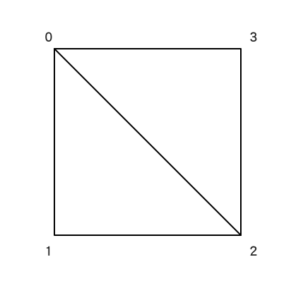
If we draw a triangle with the vertices 0, 1, and 2, and another one with the vertices 0, 2, and 3, we'll end up having a quad.
When working with OpenGL ES, we'll need to provide data using a Buffer or a subclass of a Buffer, so let's convert those arrays into Buffer:
ByteBuffer vbb = ByteBuffer.allocateDirect(quadCoords.length * (Float.SIZE / 8));
vbb.order(ByteOrder.nativeOrder());

vertexBuffer = vbb.asFloatBuffer();
vertexBuffer.put(quadCoords);
vertexBuffer.position(0);
First, we have to allocate the space we need for the Buffer. As we know the size of the array, this would be very easy: We just have to multiply it by the size of a float in bytes. One float is exactly four bytes, but we can calculate it by getting the number of bits using Float.SIZE and dividing it by 8. In Java 8, there is a new constant called Float.BYTES that precisely returns the size in bytes.
We have to indicate that the Buffer in which we put the data will have the native byte order of the platform. We can do this by calling the order() method on the Buffer with ByteOrder.nativeOrder() as a parameter. Once we've done this step, we can convert it to a float buffer by calling Buffer.asFloatBuffer() and set the data. To finish, we reset the position of the Buffer to the beginning by setting its position to 0.
We have to do this process for the vertices as well as for the indexes. As indexes are stored as short integers, we need to take that into consideration when we convert the buffer, and when calculating the size:
ByteBuffer ibb = ByteBuffer.allocateDirect(index.length * (Short.SIZE / 8));
ibb.order(ByteOrder.nativeOrder());

indexBuffer = ibb.asShortBuffer();
indexBuffer.put(index);
indexBuffer.position(0);
As we mentioned before, the OpenGL ES 2.0 rendering pipeline is handled by the vertex and the fragment shader. Let's create a helper method to load and compile the shader code:
// Source:
// https://developer.android.com/training/graphics/opengl/draw.html
public static int loadShader(int type, String shaderCode){

    // create a vertex shader type (GLES20.GL_VERTEX_SHADER)
    // or a fragment shader type (GLES20.GL_FRAGMENT_SHADER)
    int shader = GLES20.glCreateShader(type);

    // add the source code to the shader and compile it
    GLES20.glShaderSource(shader, shaderCode);
    GLES20.glCompileShader(shader);

    return shader;
}
Using this new method, we can load both the vertex and fragment shaders:
private void initShaders() {
    int vertexShader = loadShader(GLES20.GL_VERTEX_SHADER, vertexShaderCode);
    int fragmentShader = loadShader(GLES20.GL_FRAGMENT_SHADER, fragmentShaderCode);

    shaderProgram = GLES20.glCreateProgram();
    GLES20.glAttachShader(shaderProgram, vertexShader);
    GLES20.glAttachShader(shaderProgram, fragmentShader);
    GLES20.glLinkProgram(shaderProgram);
}
For the time being, let's use the default shaders from the Android developer's OpenGL training website.
The vertexShader is as follows:
// Source:
// https://developer.android.com/training/graphics/opengl/draw.html
private final String vertexShaderCode =
        // This matrix member variable provides a hook to manipulate
        // the coordinates of the objects that use this vertex shader
"uniform mat4 uMVPMatrix;" +
"attribute vec4 vPosition;" +
"void main() {" +
        // The matrix must be included as a modifier of gl_Position.
        // Note that the uMVPMatrix factor *must be first* in order
        // for the matrix multiplication product to be correct.
"  gl_Position = uMVPMatrix * vPosition;" +
"}";
The fragmentShader is as follows:
private final String fragmentShaderCode =
"precision mediump float;" +
"uniform vec4 vColor;" +
"void main() {" +
"  gl_FragColor = vColor;" +
"}";
We've added a matrix multiplication in our vertexShader, so we can modify the position of the vertices by updating the uMVPMatrix. Let's add a projection and some transformations in order to have the basic rendering in place.
We shouldn't forget about the onSurfaceChanged() callback; let's use it to set our projection matrix and define the clipping planes of our camera, taking into account the width and height of the screen to keep its aspect ratio:
@Override
public void onSurfaceChanged(GL10 unused, int width, int height) {
    GLES20.glViewport(0, 0, width, height);

    float ratio = (float) width / height;
    Matrix.frustumM(mProjectionMatrix, 0, -ratio * 2, ratio * 2, -2, 2,
    3, 7);
}
Let's compute the view matrix by using Matrix.setLookAtM() and multiplying it by the projection matrix we've just calculated on mProjectionMatrix:
@Override
public void onDrawFrame(GL10 unused) {

    ...

    Matrix.multiplyMM(mMVPMatrix, 0, mProjectionMatrix, 0, mViewMatrix,
    0);

    int mMVPMatrixHandle = GLES20.glGetUniformLocation(shaderProgram,
    "uMVPMatrix");
    GLES20.glUniformMatrix4fv(mMVPMatrixHandle, 1, false, mMVPMatrix,
    0);

    ...

}
In the preceding code, we also saw how to update a variable that can be read from a shader. To do so, we need to get the handle of the uniform variable first. By using GLES20.glGetUniformLocation(shaderProgram, "uMVPMatrix") we can get the handle of the uMVPMatrix uniform variable and, using this handle on the GLES20.glUniformMatrix4fv call, we can set the matrix we've just calculated onto it. If we check the code for the shader, we can see we've defined uMVPMatrix as uniform:
uniform mat4 uMVPMatrix;
Now that we know how to set a uniform variable, let's do the same with the color. On the fragment shader, we've set vColor as a uniform variable as well, so we can follow the same method to set it:
float color[] = { 0.2f, 0.2f, 0.9f, 1.0f };

...

int colorHandle = GLES20.glGetUniformLocation(shaderProgram, "vColor");
GLES20.glUniform4fv(colorHandle, 1, color, 0);
Using the same mechanism, but changing glGetUniformLocation to glGetAttribLocation, we can also set the vertex coordinates:
int positionHandle = GLES20.glGetAttribLocation(shaderProgram, "vPosition");

GLES20.glVertexAttribPointer(positionHandle, 3,
        GLES20.GL_FLOAT, false,
        3 * 4, vertexBuffer);
We have everything ready to draw it to the screen; we just have to enable the vertex attribute array, as we've set the coordinate data using the glVertexAttribPointer() call and glDrawElements() will only draw enabled arrays:
GLES20.glEnableVertexAttribArray(positionHandle);

GLES20.glDrawElements(
       GLES20.GL_TRIANGLES, index.length,
       GLES20.GL_UNSIGNED_SHORT, indexBuffer);

GLES20.glDisableVertexAttribArray(positionHandle);
There are many mays of drawing geometry on OpenGL, but we've used the glDrawElements() call pointing to the buffer of the face indexes we've previously created. We've used GL_TRIANGLES primitive here, but there are many other OpenGL primitives we can use. Check the official Khronos documentation about glDrawElements() for more information:
https://www.khronos.org/registry/OpenGL-Refpages/gl4/html/glDrawElements.xhtml.
Also, as good practice, and to restore the OpenGL machine state, we disable the vertex attribute array after drawing.
If we execute this code, we'll get the following-still not really useful, but it's a start!

Check the Example23-GLSurfaceView in the GitHub repository for the full example source code.