In our previous example, we've seen how to draw a quad with one single color, but what about if each vertex has a completely different color? The process will not be very different from what we've already done, but let's see how we can do it.
First, let's change the color array to hold the color of the four vertices:
float color[] = {
        1.0f, 0.2f, 0.2f, 1.0f,
        0.2f, 1.0f, 0.2f, 1.0f,
        0.2f, 0.2f, 1.0f, 1.0f,
        1.0f, 1.0f, 1.0f, 1.0f,
};
Now, in our initBuffers() method, let's initialize an additional Buffer for the color:
private FloatBuffer colorBuffer;

...

ByteBuffer cbb = ByteBuffer.allocateDirect(color.length * (Float.SIZE / 8));
cbb.order(ByteOrder.nativeOrder());

colorBuffer = cbb.asFloatBuffer();
colorBuffer.put(color);
colorBuffer.position(0);
We have to update our shaders as well to take the color parameter into account. First, on our vertexShader, we have to create a new attribute that we will call aColor to hold the color of each vertex:
private final String vertexShaderCode =
"uniform mat4 uMVPMatrix;" +
"attribute vec4 vPosition;" +
"attribute vec4 aColor;" +
"varying vec4 vColor;" +
"void main() {" +
"  gl_Position = uMVPMatrix * vPosition;" +
"  vColor = aColor;" +
"}";
Then, we define a varying vColor variable that will be passed to the fragmentShader, and the fragmentShader will compute the value per fragment. Let's see the changes on the fragmentShader:
private final String fragmentShaderCode =
"precision mediump float;" +
"varying vec4 vColor;" +
"void main() {" +
"  gl_FragColor = vColor;" +
"}";
The only thing we've changed is the declaration of vColor; instead of being a uniform variable, now it's a varying variable.
Just like we did with the vertex and face indexes, we have to set the color data to the shader:
int colorHandle = GLES20.glGetAttribLocation(shaderProgram, "aColor");
GLES20.glVertexAttribPointer(colorHandle, 4,
        GLES20.GL_FLOAT, false,
        4 * 4, colorBuffer);
Before drawing, we have to enable and disable the vertex array. If the color array is not enabled, we'll get a black square instead, as glDrawElements() will not be able to get the color information;
GLES20.glEnableVertexAttribArray(colorHandle);
GLES20.glEnableVertexAttribArray(positionHandle);
GLES20.glDrawElements(
        GLES20.GL_TRIANGLES, index.length,
        GLES20.GL_UNSIGNED_SHORT, indexBuffer);

GLES20.glDisableVertexAttribArray(positionHandle);
GLES20.glDisableVertexAttribArray(colorHandle);
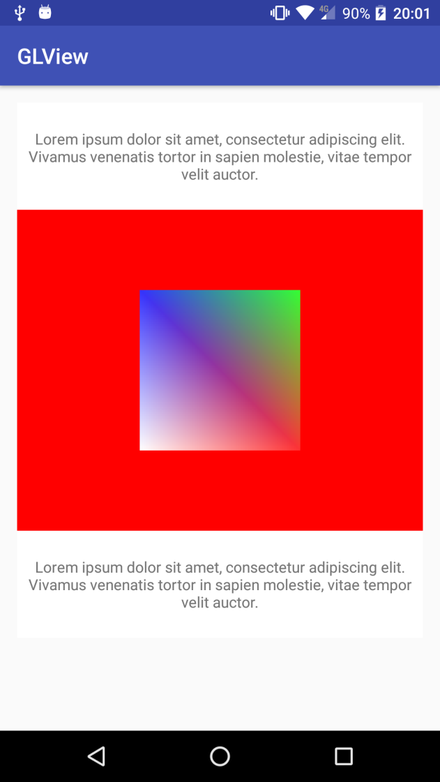
If we run this example, we'll see a similar effect as our previous example, but we can see how the color is interpolated between the vertices:
Now that we know how to interpolate colors, let's add some depth into the geometry. Everything we've drawn so far is quite flat, so let's convert the quad into a cube. It is very straightforward. Lets first define the vertices and new face indexes:
private float quadCoords[] = {
       -1.f, -1.f, -1.0f,
       -1.f,  1.f, -1.0f,
        1.f,  1.f, -1.0f,
        1.f, -1.f, -1.0f,

       -1.f, -1.f,  1.0f,
       -1.f,  1.f,  1.0f,
        1.f,  1.f,  1.0f,
        1.f, -1.f,  1.0f
};
We've replicated the same four vertices we had before, but with a displaced Z coordinate, that would add volume to the cube.
Now, we have to create the new face indexes. A cube has six faces, or quads, that can be reproduced with twelve triangles:
private short[] index = {
        0, 1, 2,        // front
        0, 2, 3,        // front
        4, 5, 6,        // back
        4, 6, 7,        // back
        0, 4, 7,        // top
        0, 3, 7,        // top
        1, 5, 6,        // bottom
        1, 2, 6,        // bottom
        0, 4, 5,        // left
        0, 1, 5,        // left
        3, 7, 6,        // right
        3, 2, 6         // right
};
Lets also add new colors for the new four vertices:
float color[] = {
        1.0f, 0.2f, 0.2f, 1.0f,
        0.2f, 1.0f, 0.2f, 1.0f,
        0.2f, 0.2f, 1.0f, 1.0f,
        1.0f, 1.0f, 1.0f, 1.0f,

        1.0f, 1.0f, 0.2f, 1.0f,
        0.2f, 1.0f, 1.0f, 1.0f,
        1.0f, 0.2f, 1.0f, 1.0f,
        0.2f, 0.2f, 0.2f, 1.0f
};
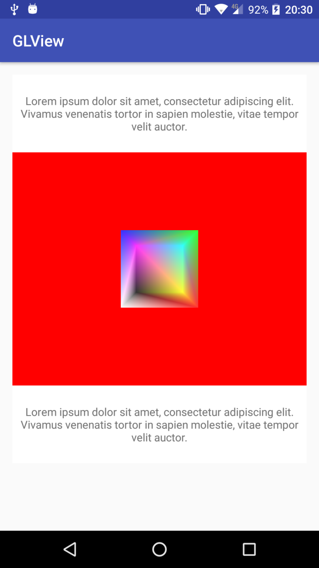
If we execute this example, as it is, we'll get a strange result, similar to the following screenshot:
Lets add a rotation transformation to the mMVPMatrix matrix to see what is going on.
We have to define a private variable to hold the rotation angle and apply the rotation to the mMVPMatrix:
private float angle = 0.f;
...
Matrix.setLookAtM(mViewMatrix, 0,
        0, 0, -4,
        0f, 0f, 0f,
        0f, 1.0f, 0.0f);

Matrix.multiplyMM(mMVPMatrix, 0, mProjectionMatrix, 0, mViewMatrix, 0); Matrix.rotateM(mMVPMatrix, 0, angle, 1.f, 1.f, 1.f);
In this case, just to see what is going on, we're applying the rotation to the three axes: x, y, and z. We also moved the camera a bit away from our previous example, as now there might be some clipping if we don't do so.
To define the amount we have to rotate by, we'll use one of the Android timers:
private long startTime;
...
@Override
public void onSurfaceCreated(GL10 unused, EGLConfig config) {
    initBuffers();
    initShaders();
    startTime = SystemClock.elapsedRealtime();
}
We store the start time on the startTime variable, and on our onDrawFrame() method we compute the angle based on the amount of time that has passed since this moment:
angle = ((float) SystemClock.elapsedRealtime() - startTime) * 0.02f;
Here, we have just multiplied it by 0.02f to limit the speed of rotation, as otherwise it'll be too fast. Doing it this way, the animation speed will be the same on all devices regardless of the rendering frame rate or their CPU speed. Now, if we run this code, we'll see the origin of the issue we're experiencing:
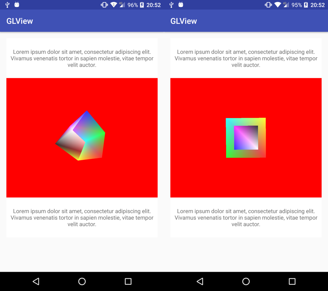
The issue is that OpenGL is not checking the z coordinate of the pixel when drawing all the triangles, so there might be some superposition and overdrawing as we can easily see in the preceding screenshots. Luckily for us, this is very easy to solve. OpenGL has a state that we can use to enable and disable depth, or z, tests:
GLES20.glEnable(GLES20.GL_DEPTH_TEST);
GLES20.glEnableVertexAttribArray(colorHandle);
GLES20.glEnableVertexAttribArray(positionHandle);
GLES20.glDrawElements(
        GLES20.GL_TRIANGLES, index.length,
        GLES20.GL_UNSIGNED_SHORT, indexBuffer);

GLES20.glDisableVertexAttribArray(positionHandle);
GLES20.glDisableVertexAttribArray(colorHandle); GLES20.glDisable(GLES20.GL_DEPTH_TEST);
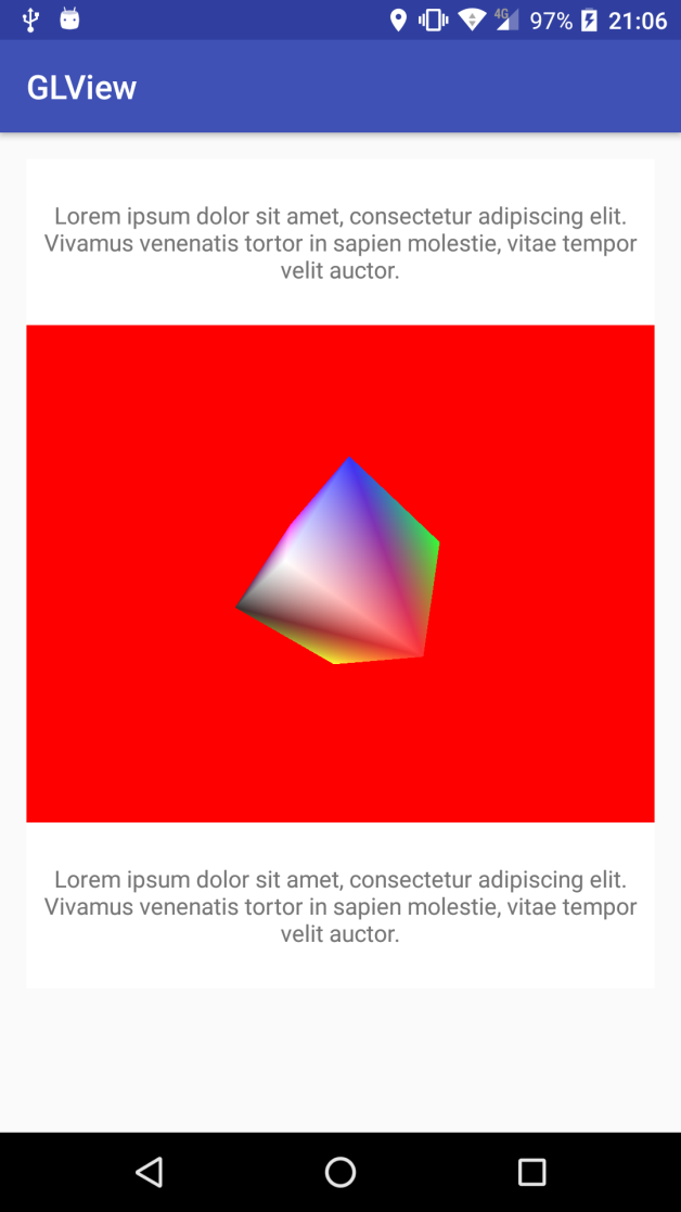
As with the previous example, after drawing we disable the state we've enabled to avoid leaving an unknown OpenGL state for any other drawing operation. If we run this code, we'll see the difference:
Check the Example24-GLDrawing on the GitHub repository for the full example source code.