Chapter 6
Buckling Analysis
In this chapter, you will learn the following:
• Introduction to Buckling Analysis
• Buckling Analysis of a Pipe Support
• Buckling Analysis of a Beam
• Buckling Analysis of a Column
In earlier chapters, you have learned about performing the static analysis of various components and assemblies. In this chapter, you will learn about performing the buckling analysis.
Introduction to Buckling Analysis
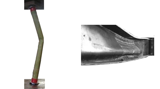
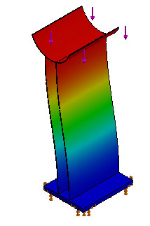
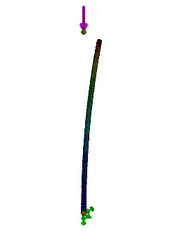
The buckling analysis is used to calculate the buckling load which is also known as the critical load. It is the load under which the model can start buckling even if the maximum stress developed in the model is within the yield strength of the material. Buckling refers to a larger deformation occurred due to the compressive axial loads acting on the structures such as long slender columns and thin sheet components, see Figure 6.1.
Figure 6.1
The minimum bucking load or critical load, when a structure can start bucking is calculated by the following formula:
F= π²EI / (KL)²
Where,
F= Minimum bucking load or Critical load
E = Modulus of elasticity
I = Area Moment of inertia of the cross-section of the structure
K = Structure (column) effective length, which depends on the end conditions
L = Length of the structure
It clear from the above formula that the buckling load does not depend upon the compressive strength of the material. As a result, the structure can buckle or fail, even if the maximum stress developed in the structure is within the compressive yield strength of the material. Also, on increasing the length of the structure, the force required to buckle the structure gets reduced.
In SOLIDWORKS Simulation, you can perform the buckling analysis of a structure to calculate the minimum bucking load factor and its associated buckling mode shape, when the structure can buckle under the compressive axial loads.
Case Study 1: Buckling Analysis of a Pipe Support
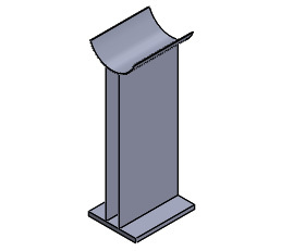
In this case study, you will perform the buckling analysis of a Pipe Support, see Figure 6.2 and determine its minimum bucking load.
Figure 6.2
Project Description
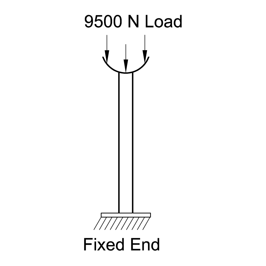
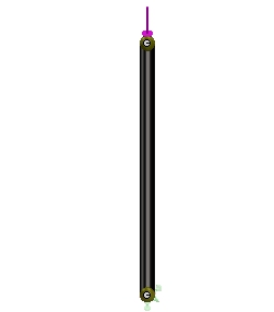
The Pipe Support is fixed at its bottom and the 9500 Newton compressive axial load is subjected on its top face, see Figure 6.3. The Pipe Support is made up of
Alloy Steel
material.
Figure 6.3
Project Summary
In this case study, you will run the buckling analysis of a Pipe Support and determine its buckling factor of safety under the applied compressive load. Also, you need to calculate the buckling load or critical load based on the buckling factor of safety.
Learning Objectives
In this case study, you will learn the following:
1. Downloading Files of Chapter 6
2. Opening the Pipe Support
3. Starting the Buckling Study
4. Applying the Material, Fixture, and Load
5. Generating the Mesh
6. Defining the Buckling modes
7. Running the Buckling Analysis
8. Displaying the Buckling Factor of Safety
9. Calculating the Buckling Load or Critical Load
10. Saving Results
Section 1: Downloading Files of Chapter 6
1. Login to the CADArtifex
website
(www.cadartifex.com)
with your user name and password. If you are a new user, first you need to register on CADArtifex website as a student.
2. After login to the CADArtifex website, click on
SOLIDWORKS Simulation > SOLIDWORKS Simulation 2018
. All resource files of this textbook appear in the respective drop-down lists.
3. Click on
Case Studies > C06 Case Studies
. The downloading of
Co6 Case Studies
file gets started. Once the downloading is complete, you need to unzip the downloaded file.
4. Save the unzipped
C06 Case Studies
file in the
Case Studies
folder inside the
SOLIDWORKS Simulation
folder.
Section 2: Opening the Pipe Support
1. Start SOLIDWORKS, if not already started.
2. Click on the
Open
button in the
Welcome
dialog box or the
Open
tool in the
Standard
toolbar. The
Open
dialog box appears.
3. Browse to the location
> SOLIDWORKS Simulation > Case Studies > C06 Case Studies > Case Study 1
. Next, select the
Pipe Support
and then click on the
Open
button in the dialog box. The Pipe Support is opened in SOLIDWORKS.
Section 3: Starting the Buckling Study
1. Click on the
Simulation
tab in the
Simulation
CommandManager
. The tools of the
Simulation
CommandManager
appear.
2. Click on the
New
Study
tool in the
Simulation
CommandManager
. The
Study
PropertyManager
appears at the left of the graphics area.
3. Click on the
Buckling
button in the
Advanced
Simulation
rollout of the
Study
PropertyManager
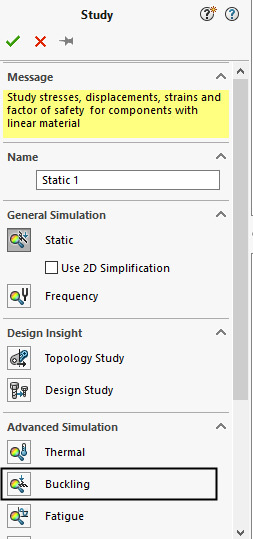
to perform the buckling analysis, see Figure 6.4.
Figure 6.4
4. Enter
Pipe Support
Buckling Study
in the
Study
name
field of the
Name
rollout in the PropertyManager.
5. Click on the green tick-mark button in the PropertyManager. The
Pipe Support
Buckling Study
is
added in the
Simulation Study Tree.
Section 4: Applying the Material, Fixture, and Load
Now, you need to apply the material, fixture and load to the model. The procedures to apply the material, fixture, and load in the Buckling analysis are the same as in the static analysis.
1. Invoke the
Material
dialog box by clicking on the
Apply
Material
tool in the
Simulation
CommandManager
and then apply the
Alloy Steel
material. Next, close the dialog box.
Now, you need to apply the Fixed Geometry fixture.
2. Right-click on the
Fixtures
option in the Simulation Study Tree and then click on the
Fixed
Geometry
tool in the shortcut menu appeared. The
Fixture
PropertyManager
appears.
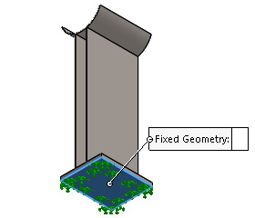
3. Rotate the model such that you can view the bottom face of the Pipe Support model and then select it to apply the Fixed Geometry fixture, see Figure 6.5. Next, click on the green tick-mark button in the PropertyManager.
Now, you need to apply the compressive axial load on the top face of the model.
4. Right-click on the
External
Loads
option in the Simulation Study Tree and then click on the
Force
tool in the shortcut menu appeared. The
Force/Torque PropertyManager
appears.
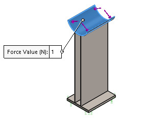
5. Change the orientation of the model to isometric and then select the top semi-cylindrical face of the Pipe Support model to apply the load, see Figure 6.6.
Figure 6.6
6. Select the
Selected direction
radio button in the PropertyManager. The
Face, Edge, Plane for Direction
field appears.
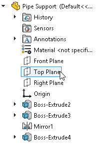
7. Expand the FeatureManager Design Tree, see Figure 6.7. Next, click on the
Top Plane
as the reference plane to define the direction of force.
8. Click on the
Normal to Plane
button in the
Force
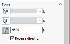
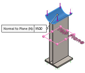
rollout of the PropertyManager and then enter
9500
as the axial load acting on the model, see Figure 6.8.
Figure 6.8
9. Select the
Reverse
direction
check box in the
Force
rollout to reverse the direction of force downward, see Figure 6.9.
Figure 6.9
10. Click on the green tick-mark button in the PropertyManager. The specified compressive axial load is applied on the Pipe Support.
Section 5: Generating the Mesh
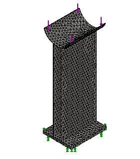
1. Generate the curvature-based mesh with the default mesh parameters by using the
Create Mesh
tool. Figure 6.10 shows the meshed model.
Figure 6.10
Section 6: Defining the Buckling modes
Now, you need to define the required number of buckling modes to be calculated by the program. By default, SOLIDWORKS Simulation calculates the first buckling mode of the model.
1. Right-click on the
Pipe Support Buckling Study
(
name of the study
)
in the Simulation Study Tree and then click on the
Properties
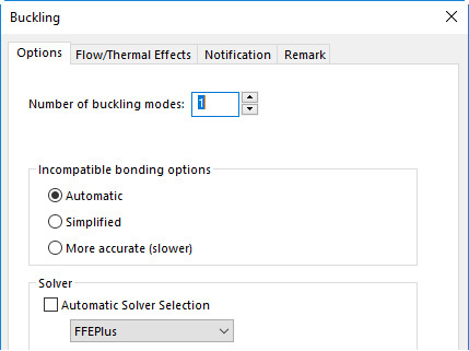
tool in the shortcut menu appears, see Figure 6.11. The
Buckling
dialog box appears, see Figure 6.12.
Figure 6.11
Figure 6.12
2. Enter
5
in the
Number of buckling modes
field of the
Options
tab in the dialog box to calculate five different buckling safety factors and the associated buckling modes for the Pipe Support.
3. Click on the
OK
button in the dialog box.
Section 7: Running the Buckling Analysis
1. Click on the
Run This Study
tool in the
Simulation
CommandManager
. The
Pipe Support
Buckling Study
(
name of the study
)
window appears which displays the progress of analysis. After the analysis completes, the
Results
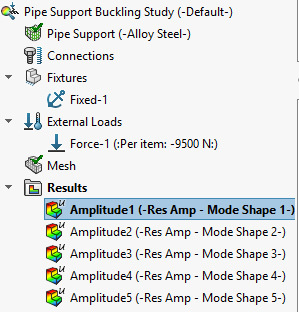
folder is added in the Simulation Study Tree with the five different mode shapes, see Figure 6.13. By default, the
Amplitude1 (-Res Amp - Mode Shape 1-)
is
activated in the
Results
folder. As a result, the first buckling mode shape of the model, which occurs first when the model starts buckling, appears in the graphics area, see Figure 6.14.
Figure 6.13
Figure 6.14
You can also display the remaining buckling mode shapes of the model by double-clicking on the respective option in the
Results
folder of the Simulation Study Tree.
Section 8: Displaying the Buckling Factor of Safety
Now, you need to display the buckling factor of safety of the Pipe Support.
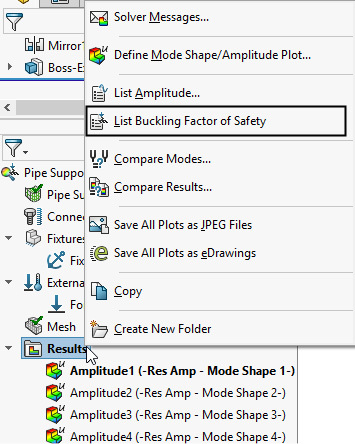
1. Right-click on the
Results
folder in the Simulation Study Tree and then click on the
List Buckling Factor of Safety
tool in the shortcut menu appeared, see Figure 6.15. The
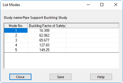
List Modes
dialog box appears, see Figure 6.16.
Figure 6.15
Figure 6.16
The
List Modes
dialog box displays the specified number of buckling modes and the associated buckling factor of safety of each mode. The first buckling load factor is always smaller than the other buckling load factors and for any given load, it occurs first. Therefore, you can calculate the buckling load or critical load when the model can start buckling by using the first buckling factor of safety.
In this study, the first calculated buckling factor of safety is
16.399
. It means that the design is safe.
NOTE:
The buckling load factor is the ratio of buckling/critical load to the applied load.
Buckling Load Factor = Buckling Load / Applied Load
If the buckling load factor is greater than 1, the design is considered to be safe. If the buckling load factor is equal to 1 then the buckling starts occurring in the design. If the buckling load factor is less than 1, the design is considered to be failure and the buckling occurs in the design.
2. Close the
List Modes
dialog box.
Section 9: Calculating the Buckling Load or Critical Load
Now, you need to calculate the buckling load when the Pipe Support start buckling.
1. Calculate the buckling load by using the following formula.
Buckling Load = Buckling Load Factor X Applied Load
=
16.399 X 9500 N
= 155790.5 N
The 155790.5 N load is the calculated buckling load or critical load when the Pipe Support can start buckling.
Section 10: Saving Results
Now, you need to save the model and its results.
1. Click on the
Save
tool in the
Standard
toolbar. The model and its results are saved in the location
> SOLIDWORKS Simulation > Case Studies > C06 Case Studies > Case Study 1
.
2. Close the SOLIDWORKS session.
Case Study 2: Buckling Analysis of a Beam
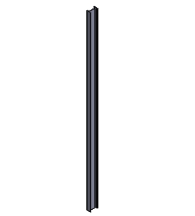
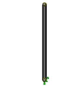
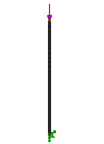
In this case study, you will perform the buckling analysis of a long Beam, see Figure 6.17. Determine the bucking load or critical load when the Beam can start buckling.
Project Description
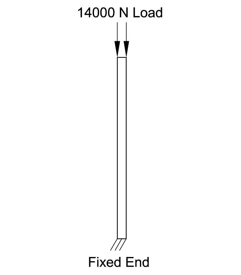
The Beam is fixed at its bottom and the 14000 Newton compressive axial load is subjected on its top face, see Figure 6.18. The Beam is made up of
AISI 304
steel
material.
Figure 6.17
Figure 6.18
Project Summary
In this case study, you will run the buckling analysis of a beam and determine the buckling factor of safety of the beam under the applied compressive load. Also, you need to calculate the buckling load or critical load based on the buckling factor of safety of the beam.
Learning Objectives
In this case study, you will learn the following:
1. Starting the Buckling Analysis
2. Applying the Material, Fixture, and Load
3. Generating the Mesh
4. Running the Buckling Analysis
5. Displaying the Buckling Factor of Safety
6. Calculating the Buckling Load or Critical Load
7. Saving Results
Section 1: Starting the Buckling Analysis
1. Start SOLIDWORKS and then open the Beam model from the location
> SOLIDWORKS Simulation > Case Studies > C06 Case Studies > Case Study 2
.
NOTE:
You need to download the C06 Case Studies file by logging to the CADArtifex website (www.cadartifex.com), if not downloaded earlier.
2. When the Beam model is opened in SOLIDWORKS, click on the
Simulation
tab in the
Simulation
CommandManager
. The tools of the
Simulation CommandManager
appear.
3. Click on the
New
Study
tool in the
Simulation
CommandManager
. The
Study
PropertyManager
appears at the left of the graphics area.
4. Click on the
Buckling
button in the
Advanced
Simulation
rollout of the
Study
PropertyManager
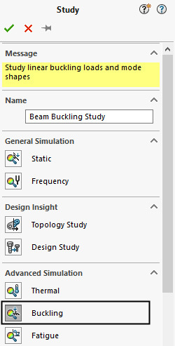
to perform the buckling analysis, see Figure 619.
5. Enter
Beam
Buckling Study
in the
Study
name
field of the
Name
rollout in the PropertyManager, see Figure 619.
Figure 6.19
6. Click on the green tick-mark button in the PropertyManager. The
Beam Buckling Study
is
added in the
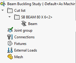
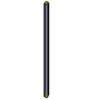
Simulation Study Tree, see Figure 6.20. Also, the joints appear on the beam member in the graphics area, see Figure 6.21. It is because, SOLIDWORKS Simulation, automatically identifies the geometry as a beam and calculates its joints.
Figure 6.20
Figure 6.21
Section 2: Applying the Material, Fixture, and Load
Now, you need to apply the material, fixture and load on the beam.
1. Invoke the
Material
dialog box by clicking on the
Apply Material
tool in the
Simulation
CommandManager
and then apply the
AISI 304
steel
material. Next, close the dialog box.
Now, you need to apply the Fixed Geometry fixture.
2. Right-click on the
Fixtures
option in the Simulation Study Tree and then click on the
Fixed
Geometry
tool in the shortcut menu appeared. The
Fixture PropertyManager
appears.
3. Select the yellow joints appeared at the bottom of the beam in the graphics area, see Figure 6.22. Next, click on the green tick-mark button in the PropertyManager. The Fixed Geometry fixture is applied at the bottom joint of the beam.
Figure 6.22
Now, you need to apply the compressive axial load on the top joint of the beam.
4. Right-click on the
External
Loads
option in the Simulation Study Tree and then click on the
Force
tool in the shortcut menu appeared. The
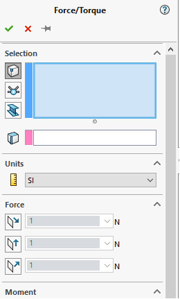
Force/Torque PropertyManager
appears, see Figure 6.23.
By default, the
Vertices,
Points
button is activated in the
Selection
rollout of the PropertyManager. As a result, you can select the vertices and points of the beam members to apply the load. On selecting the
Joints
button, you can select a beam joint to apply the load.
5. Click on the
Joints
button in the
Selection
rollout of the PropertyManager to select the beam joint for applying the load.
6. Select the top beam joint. The name of the selected beam joint appears in the field of the
Selection
rollout in the PropertyManager.
7. Click on the
Face, Edge, Plane for Direction
field of the
Selection
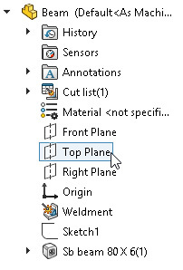
rollout in the PropertyManager. Next, expand the FeatureManager Design Tree and then click on the
Top Plane
as the reference plane to define the direction of force, see Figure 6.24.
Figure 6.24
8. Make sure that the
SI
is selected as the unit in the
Unit
drop-down list of the
Units
rollout in the PropertyManager.
9. Click on the
Normal to Plane
button in the
Force
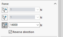
rollout of the PropertyManager and then enter
14000
as the axial load on the beam, see Figure 6.25.
Figure 6.25
10. Select the
Reverse
direction
check box in the
Force
rollout to reverse the direction of force downward, see Figure 6.26.
Figure 6.26
11. Click on the green tick-mark button in the PropertyManager. The specified compressive axial load is applied on the beam.
Section 3: Generating the Mesh
1. Right-click on the
Mesh
option in the Simulation Study Tree and then click on the
Create
Mesh
tool in the shortcut menu appeared. The
Mesh Progress
window appears and the process of meshing the beam starts. After it is complete, the meshed beam with beam elements, which are represented by hollow cylinders, appear in the graphics area, see Figure 6.27.
Figure 6.27
Section 4: Running the Buckling Analysis
1. Click on the
Run This Study
tool in the
Simulation
CommandManager
. The
Beam
Buckling Study
(
name of the study
)
window appears which displays the progress of analysis. When it is complete, the
Results
folder is added in the Simulation Study Tree with the resultant amplitude of the first mode shape. Also, the first mode shape of the beam appears in the graphics area, see Figure 6.28.
Figure 6.28
Section 5: Displaying the Buckling Factor of Safety
Now, you need to display the buckling factor of safety of the beam.
1. Right-click on the
Results
folder in the Simulation Study Tree and then click on the
List Buckling Factor of Safety
tool in the shortcut menu appeared. The
List Modes
dialog box appears, see Figure 6.29.
NOTE:
The
List Modes
dialog box displays the number of specified buckling modes and the associated buckling factor of safety of each mode. By default, SOLIDWORKS Simulation, calculates the first buckling factor of safety. It is because, the first buckling load factor is always smaller and for any given load, it occurs first. However, as discussed in the Case Study 1, you can specify multiple buckling modes and the associated buckling factors of safety to be calculated by the program.
Figure 6.29
The calculated buckling factor of safety is
0.57331
. It means that the design is considered to be failure and the buckling starts when the applied load is equal to
8026.34 N
[14000 (applied load) X 0.57331 (buckling load factor)]. Note that you may find difference in the results due to the service packs installed on your system.
Section 6: Calculating the Buckling Load or Critical Load
Now, you need to calculate the buckling load when the beam can start buckling.
1. Calculate the buckling load by using the following formula.
Buckling Load = Buckling Load Factor X Applied Load
= 0.57331 X 14000
= 8026.34 N
Section 7: Saving the Results
Now, you need to save the results.
1. Click on the
Save
tool in the
Standard
toolbar. The model and its results are saved in the location
> SOLIDWORKS Simulation > Case Studies > C06 Case Studies > Case Study 2
.
2. Close the SOLIDWORKS Simulation session.
Hands-on Test Drive 1: Buckling Analysis of a Column
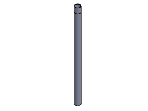
Perform the buckling analysis of a long hollow column shown in Figure 6.30 and determine the buckling load or critical load when the column can start buckling.
Figure 6.30
Project Description
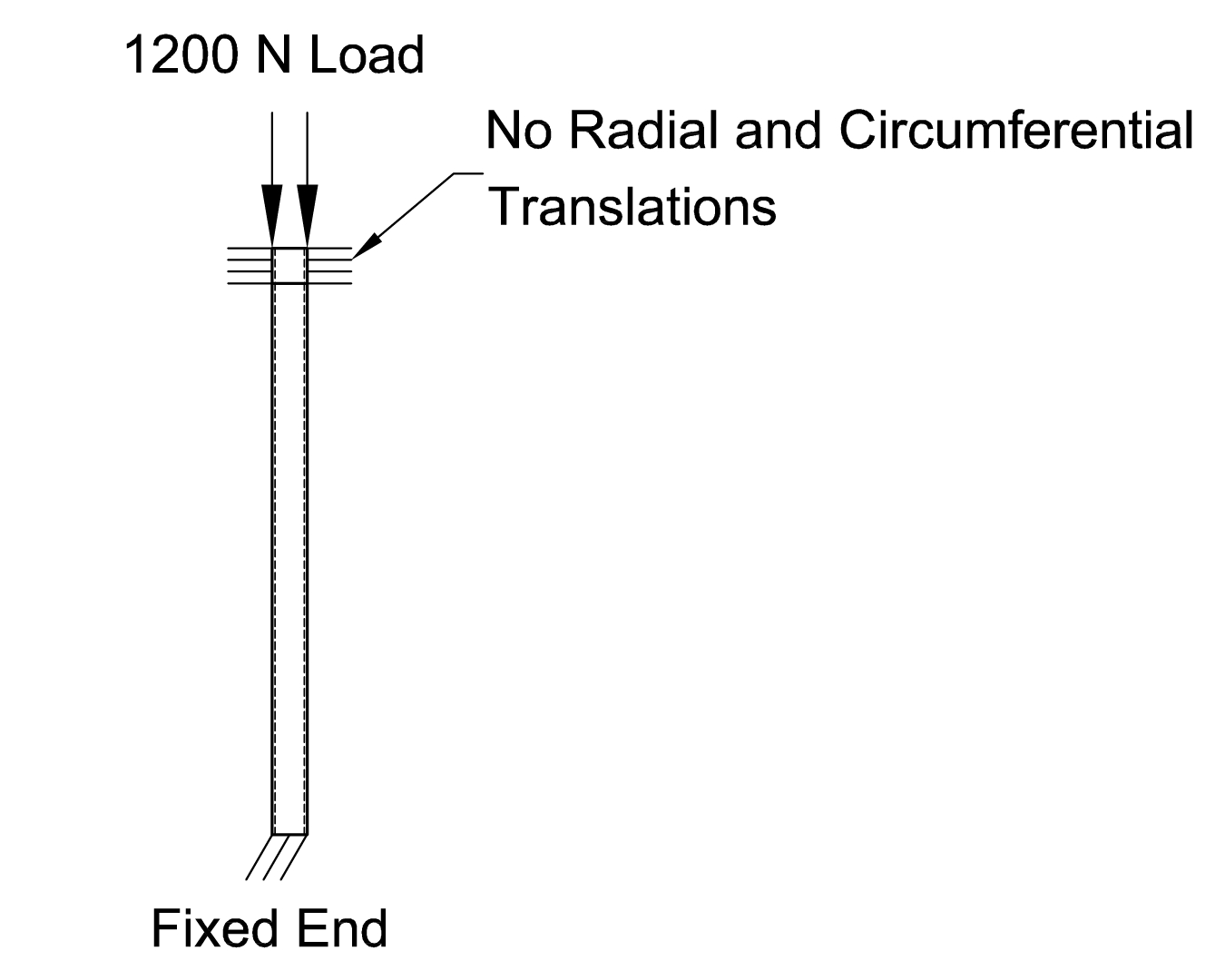
The column is clamped at its both ends (top and bottom). You need to apply the Fixed Geometry fixture at the bottom face of the column to represent its clamped connection with the ground, see Figure 6.31. To represent the clamped connection at the top of the column, you need to restrict the radial and circumferential translations of the column at the top so that the column can only translate along its axial direction due to the applied load, see Figure 6.31. The column is subjected to the 1200 Newton compressive axial load on its top, see Figure 6.31. The column is made up of Alloy Steel
material.
Figure 6.31
Hint:
To restrict the radial and circumferential translations of the column at the top, you can apply the On Cylindrical Faces fixture and specify the 0 values for the radial and circumferential translations.
Project Summary
In this case study, you will run the buckling analysis of a column which is clamped at its both ends and determine the buckling factor of safety of the beam under the applied compressive load. You also need to calculate the buckling load or critical load based on the minimum buckling factor of safety of the column when it can start buckling.
Summary
In this chapter, you have learned about the concept of the buckling analysis. You have also learned about performing the buckling analysis of various case studies. Also, you have learned how to calculate the buckling load or critical load when the structure can start buckling.
Questions
• The ________ refers to the larger deformation occurred on a structure due to the compressive axial loads
.
• The buckling load is also known as the ________ , when the model can start buckling
.
• A structure can buckle even if the maximum stress developed in the structure is within the ________ strength of the material.
• The ________ field of the
Buckling
dialog box is used to specify the number of buckling modes to be calculated by the program.
• The ________ tool is used to display the specified number of buckling modes and the associated buckling factor of safety.
• For any given load, the ________ calculated buckling factor of safety is always smaller than the other buckling load factors.
• The ________ dialog box displays the specified number of buckling modes and the associated buckling factor of safety of each mode.
• The buckling load factor is the ratio of ________ load to the ________ load.
• If the buckling load factor is greater than 1, the design is consider to be ________.
• If the buckling load factor is less than 1, the design is consider to be ________ and the buckling occurs in the design due to the applied load.
• On increasing the length of a structure, the force required to buckle it gets ________.
• The buckling load or critical load does not depend upon the ________ strength of the material.
• You can calculate the buckling load or critical load of a structure, when it can starts buckling, by using the ________ buckling factor of safety.
