Chapter 5. 2D Graphics
Unity is best known as a 3D game engine, but it’s just as capable for working with 2D graphics. In this chapter, we’ll discuss how to put together a game designed for a flat perspective.
Note
None of the concepts covered in this chapter are restricted to 2D games!
Recipes in this chapter revolve around concepts related to 2D graphics, such as sprites, and collisions between sprites, particle effects, and sprite sorting.
5.1 Importing Sprites
Solution
-
Drag and drop the images into your project.
-
Select the images and set the Texture Type to “Sprite (2D and GUI)” (Figure 5-1).

Figure 5-1. Setting the texture type for a sprite
-
Click Apply.
-
You can now use this image as a sprite.
Discussion
If your project was created with the 2D template, incoming sprites will automatically be set up this way. Otherwise, images are imported as textures, for use in materials for 3D models.
You can change your project to behave this way by going Edit → Project Settings → Editor and setting Default Behavior Mode to 2D (Figure 5-2). This will also make any new scenes you create have a different set of initial objects—they won’t have a light or skybox.
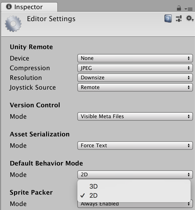
Figure 5-2. Setting the default mode for a project to 2D. This, among other things, makes all new textures default to sprites.
5.2 Adding a Sprite to the Scene
Solution
-
First, ensure that your image is configured to be a sprite (Figure 5-1).
-
Drag and drop it into your scene.
When you do, Unity will create a game object for you with the name of the sprite, add a SpriteRenderer component to it, and make the SpriteRenderer display the sprite.
Discussion
The Pixels Per Unit value controls the relationship between the size of the source image in pixels and the size of the sprite in the scene. If a sprite is 1 pixel per unit, then each pixel will be 1 unit in width and height; if a sprite is 100 pixels per unit, then each pixel will be 1/100 of a unit in width and height.
5.3 Creating a Sprite Animation
Solution
Select the images that you want to play as part of an animation, and drag them into the scene.
Unity will do the following for you:
-
Create a new animator controller asset and save it next to the image assets you dragged in.
-
Create a new animation clip and ask you where to save it. The animation clip will be configured to update the sprite over time. The animation clip will also loop.
-
Add the animation clip as a state in the animator controller.
-
Create a new game object that has an
Animatorand aSpriteRenderercomponent.
You can test the animation by playing the game.
Discussion
If you already have an object set up with an Animator, you can attach new animation states to it. We discuss how to do this in detail in Chapter 8; the only difference between 3D animations, which that chapter covers, and 2D animations is that the animation clips modify the sprite renderer’s Sprite field, rather than the positions of 3D transforms.
5.4 Creating a Sprite with 2D Physics
Solution
-
Add a game object with a sprite renderer to your scene.
-
Select the game object and click Add Component.
-
Select Physics 2D → Rigidbody 2D, or type
Rigidbody 2Dinto the search field and select it.
Much like regular Rigidbody objects, which work in three dimensions, Rigidbody2D objects define the mass and position of a physical object and respond to physical forces. However, they don’t define a shape on their own. To add a shape, you need to add a collider.
Discussion
As with regular colliders, you can’t have more than one 2D collider on an object. If you want a more complex shape, either use a polygon collider or create child game objects that have a different collider. The child objects don’t need to have their own rigidbody.
You can edit polygon colliders after they’ve been added. To do this, select the object that has the polygon collider component attached and click the Edit Collider button. You can now reposition the points of the polygon by dragging them around, add new points by clicking and dragging on the lines between the points, and remove a point by holding the Control key and clicking a point.
5.5 Customizing Sprite Collision Shapes
Solution
-
Select the sprite you want to configure, and ensure that Generate Physics Shape is turned on (Figure 5-3).
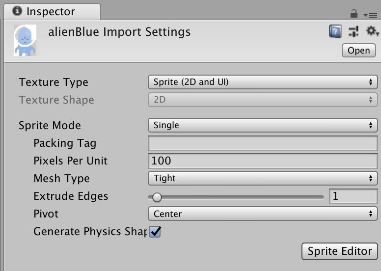
Figure 5-3. Enabling the Generate Physics Shape option in the import settings for a sprite texture
-
Click the Sprite Editor button. The Sprite Editor window will appear.
-
In the drop-down list at the top-left corner, select Custom Physics Shape.
You can now begin defining the shape of the sprite (Figure 5-4).
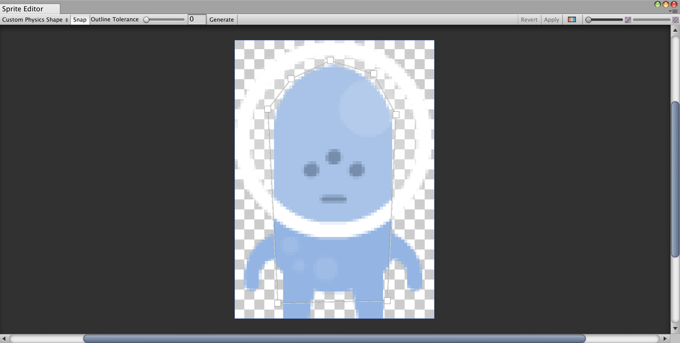
Figure 5-4. Creating the shape for a sprite
-
Click and drag to add a new path to the shape.
-
Click the points of a path to move them.
-
Click and drag between two points to insert a new point between them. (You can also hover over the line, and click to add new points!)
-
Click a point and press Command-Delete (Control-Delete on a PC) to delete it.
-
When you’re done, click Apply.
Discussion
The physics outline is used as the default shape when you add a polygon collider to an object that has a sprite renderer (Figure 5-5). If a sprite doesn’t have a physics outline set up in it, Unity generates one for you using the transparent regions of the sprite. Unity will generally try to create a very close outline, which means that the default shape is often more complex than it needs to be. When you customize the physical outline of a sprite, you can provide a simpler shape for the physics system to use.

Figure 5-5. The physics shape in use
5.6 Using a Composite Collider
Solution
-
Create your game objects that have the individual colliders. These can be any type of 2D collider, such as a box, polygon, or circle.
-
Create an empty game object, and make it the parent of the objects with colliders.
-
Finally, select the child game objects and select the Used By Composite checkbox (Figure 5-6). When you select the parent object, its collider shape will be defined by combining the shapes of its children.
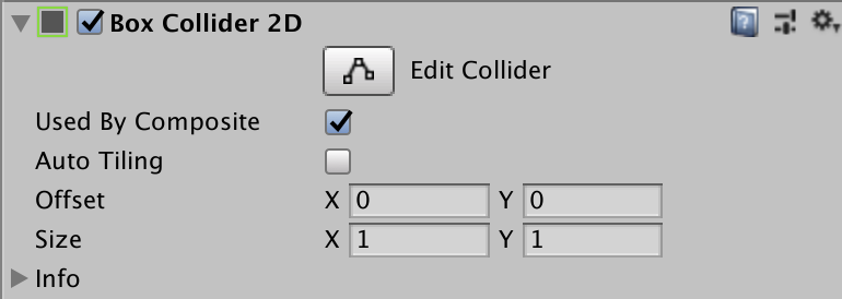
Figure 5-6. Enabling the Used By Composite option on a collider
Discussion
Composite colliders can be more efficient and also prevent problems caused by two colliders that are right next to each other. When two flat colliders are next to each other, an object sliding over them can “trip” over the point where they meet, because of precision problems that affect most physics engines. This problem is solved by removing the corner completely.
Figure 5-7 shows an example of this. The top object contains three box colliders in a row, with the lines between them visible. The bottom object also has three box colliders in a row, but configured to be part of a composite collider. The lines between them are gone, and the final collider is one large rectangular shape with no corners.
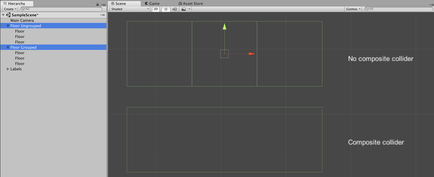
Figure 5-7. Two groups of colliders; the group at the top does not use a composite collider, and the individual outlines of the shapes can be seen. The group at the bottom does use a composite collider, and the shapes have been merged into a single outline.
5.7 Using the Sprite Packer
Discussion
A texture atlas is a single texture that contains multiple images. When the game is built, Unity collects all of the sprites in the atlas, and builds a single texture image that packs them all together; during gameplay, when a sprite renderer needs to display its sprite, the subsection of the atlas that contains the necessary data is used.
Texture atlasing can lead to better performance. If multiple sprite renderers are using sprites that are stored in the same atlas, they can be drawn at the same time. Additionally, the packing process trims the edges from a sprite, which reduces the amount of memory needed to store the final image.
You don’t need to do anything to use an atlas, besides creating the atlas itself. Sprite renderers will automatically use an atlas texture if the sprite they need to draw is stored inside one.
5.8 Applying Forces to 2D Objects
Solution
You can apply forces to a 2D object through a script, using the Rigidbody2D class’s AddForce method.
The following script demonstrates how to use player input to apply forces to an object:
publicclassAlienForce:MonoBehaviour{// The amount of force to apply.[SerializeField]floatverticalForce=1000;[SerializeField]floatsidewaysForce=1000;// A cached reference to the Rigidbody2D on this object.Rigidbody2Dbody;// On game start, get the reference to the rigid body and cache it.voidStart(){body=GetComponent<Rigidbody2D>();}// You will get smoother movement if you apply physical forces in// FixedUpdate, because it's called a fixed number of times per second,// with a fixed simulation timestep, which means more stable simulationvoidFixedUpdate(){// Get user input, and scale it by the amount of force we want to// applyvarvertical=Input.GetAxis("Vertical")*verticalForce;varhorizontal=Input.GetAxis("Horizontal")*sidewaysForce;// Generate a force vector from these inputs, scaled by timevarforce=newVector2(horizontal,vertical)*Time.deltaTime;// Add the force to the spritebody.AddForce(force);}}
Note
It’s not especially practical for such a small example, but input would typically be collected in Update, rather than FixedUpdate as we did here. FixedUpdate can run more than once per render frame, which can mean you end up with extra input!
Discussion
Unlike Rigidbody components, which operate in three dimensions, Rigidbody2D components operate only in two dimensions. This means that all the forces you apply are Vector2D, rather than Vector3D. Additionally, because there’s ony one degree of rotational freedom, you can apply rotation only on one axis.
In addition to applying forces with code, you can also use a ConstantForce2D component (Figure 5-8). These components, as their name suggests, continuously apply a force on an object. They’re good for objects and effects where you know that something needs to move around, but you don’t really need to have control over it.
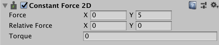
Figure 5-8. A ConstantForce2D component
5.9 Creating a Conveyor Belt
Solution
Surface effectors apply forces that push bodies along the edges of the effector:
-
Create a new game object, and add a
BoxCollider2Dcomponent to it. Name it “Conveyor Belt.” -
Turn on the Used By Effector setting (Figure 5-9).
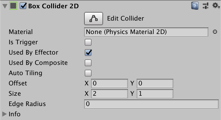
Figure 5-9. Enabling the Used By Effector option on a collider
-
Add a
SurfaceEffector2Dcomponent by clicking the Add Component button and choosing Physics 2D → Surface Effector 2D (Figure 5-10).

Figure 5-10. The settings of a SurfaceEffector2D component
-
Place above it any object with a
Rigidbody2Dand aCollider2Dattached. -
Run the game. The object will fall onto the effector and be pushed by it.
Discussion
Effectors work with colliders to apply forces to objects. When an object that has a Rigidbody2D collides with a Collider2D that has an effector, the effector applies forces to it based on the effector’s type and settings. (If the effector’s Collider2D component is marked as a trigger, forces are applied to objects within the bounds.)
There are multiple effectors in Unity’s 2D physics engine. For example, point effectors can attract and repel objects from a single point in space, buoyancy effectors apply an upward force that mimics buoyancy, and platform effectors create forces that enable one-way movement through objects.
5.10 Using a Custom Material for Sprites
Solution
-
Create a new material asset by opening the Assets menu and choosing Create → Material. Name the new material “Sprite Diffuse.”
-
Select the new sprite, and at the top of the Inspector, change the shader to Sprites → Diffuse (Figure 5-11).
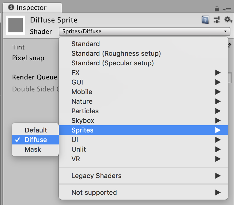
Figure 5-11. Selecting the Sprite → Diffuse shader on a material
-
Select any game object in your scene that has a sprite renderer, and drag your Sprite Diffuse material into its Material slot. It will now respond to lighting (Figure 5-12).
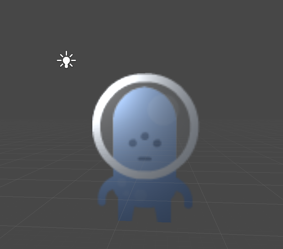
Figure 5-12. A sprite using the Diffuse shader. It’s now shaded and responds to light.
Discussion
The default shader ignores lights—the color of the texture is what’s used onscreen (as opposed to being shaded by the environment).
Note
If you plan on lighting your sprites, you should design your sprites to be very bright. Unless the sprite is hit straight-on by bright light, it will be darker than it appears in the texture.
5.11 Managing Sprite Sorting
Discussion
The Order in Layer setting controls the drawing order of a sprite within its sorting layer. And there’s always at least one sorting layer, called Default, which can’t be removed.
To create sorting layers open the Edit menu, and choose Project Settings → Tags & Layers. Create your sorting layer, and rearrange their order (Figure 5-13).
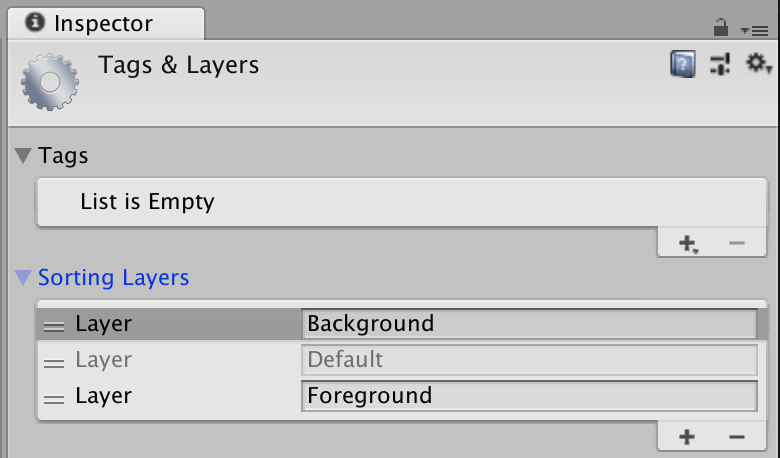
Figure 5-13. Creating and configuring sorting layers
Use Sorting layers to ensure that large sprite collections are drawn above or below other collections: for example, you might create one sorting layer called Background and another called Characters; objects on the Background sorting layer are always drawn behind objects on the Characters layer, regardless of their Order in Layer property.
You can select a sorting layer for a sprite renderer by changing its Sorting Layer property in the Inspector (Figure 5-14).
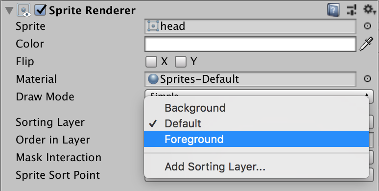
Figure 5-14. Selecting a sorting layer for a sprite renderer
Sorting layers have a similar name to Layers, but they’re a different thing. Two objects can be on different sorting layers while being on the same layer.
5.12 Using Sorting Groups
Solution
Use a sorting group to manage the sorting order of sprites:
-
Create an empty game object. Name it “Sprite Group.”
-
Move any sprite renderers that you want to stay in sorted order so they’re children of this object.
The sprites will now stay in that order, regardless of any other objects that might be in the same screen area.
Discussion
Sorting groups ensure that all members of that group are drawn together, and that no other objects can be drawn between them.
For example, Figure 5-15 and Figure 5-16 both show two characters, each of which is composed of a number of other sprites. These sprites have their sort order configured so that, for example, the head is drawn on top of the body, and one of the arms is drawn behind the body. In Figure 5-15, the two characters have a sorting group on their parent object, while in Figure 5-16, they don’t. This results in the various body parts incorrectly overlapping the other character’s.

Figure 5-15. Two groups of sprites, each with a sorting group attached to its parent. The two characters are sorted separately from each other.
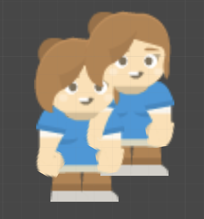
Figure 5-16. The same two groups of sprites, with the sorting group disabled. Because the sprites are on the same layer and have the same sorting orders, parts of the two characters overlap each other.
5.13 Creating a 2.5D Scene
Solution
-
Select your camera and change its Projection mode to Perspective.
-
Select your background objects and move them farther away from the camera.
When the camera moves from side to side, objects farther from the camera will move “slower,” just as 3D objects (and real-life objects) do, which creates a sense of depth.
Note that when you’re using a perspective camera, you’re more prone to encountering sorting issues, especially when your sprites aren’t directly facing the camera. Use sorting groups to ensure that 2D objects are sorted correctly.
Discussion
There are lots of different styles of “2.5.” For example, you can use multiple flat planes and get a parallax effect, which means that your art assets are still flat, painted sprites, but the player gets an impression of them existing in a deeper environment. Many games use this technique; for example, a game that we helped on, Night in the Woods, is made almost entirely out of flat sprites, but some of them are farther from the camera. Because the camera’s Projection mode is set to Perspective, distant objects move slower, which reinforces a feeling of distance.
Another technique is to combine 2D sprites with a 3D background. For example, in Ducktales: Remastered, all the characters are 2D sprites, but they’re moving around in 3D environments. This works particularly well for platformers, because it highlights the vertical walls that you can’t move through, and creates a much more dynamic environment when the camera is allowed to move up and down, which exposes multiple views of the background.