The following are needed for this step:
- Pycom LoPy/LoPy 4 microcontroller
- FTDI adapter or Pycom expansion board
- Antenna pig tail and antenna
- Breadboard and jumpers
- Atom IDE
- USB cable
Let's begin:
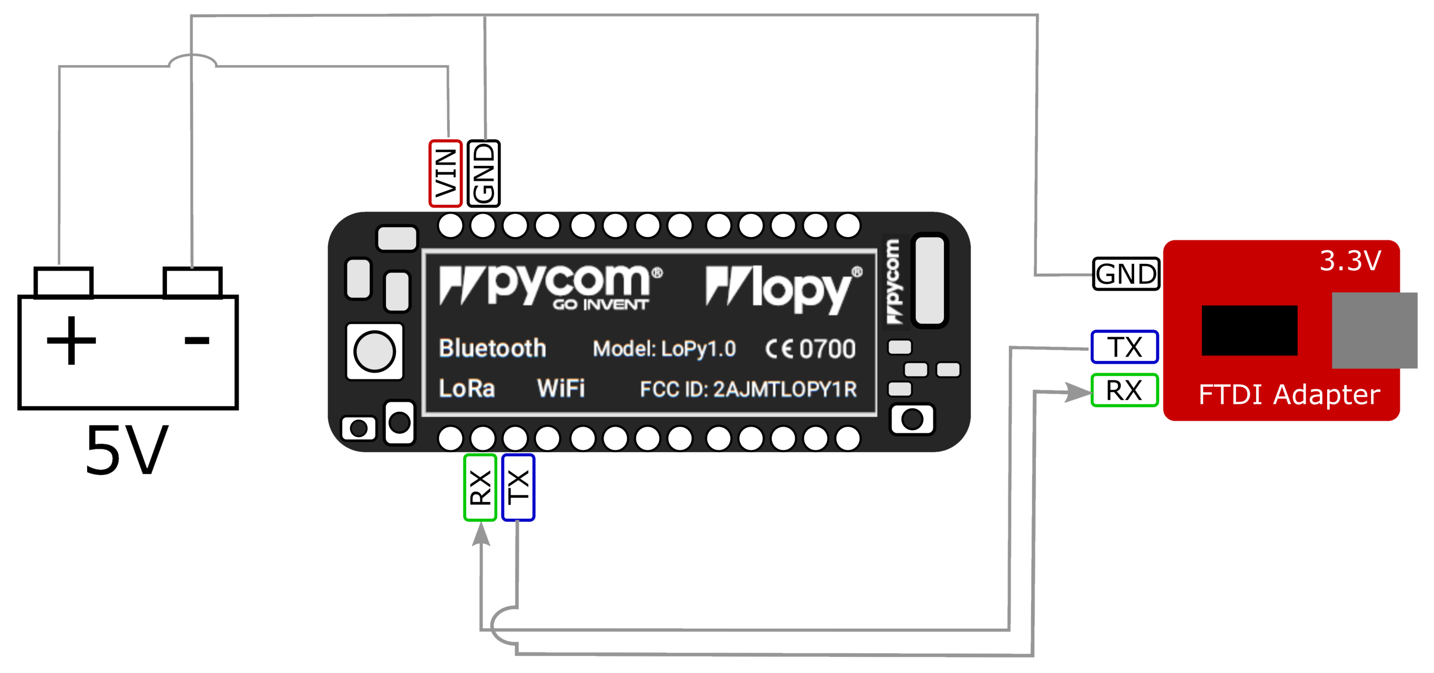
- For those who have purchased a Pycom expansion board, you can use it to connect the LoPy/LoPy 4 to your computer. If not, you can use an FTDI USB to TTL serial adapter. If you have the option of either, choose the FTDI USB to TTL serial adapter as it will be easier to follow the tutorial with this setup. Refer to the following diagram to hook up a LoPy/LoPy 4 to an FTDI adapter. Be sure to use a 3.3V FTDI adapter to avoid damaging the LoPy/LoPy 4:
- To start programming the Pycom LoPy/LoPy 4, we will need an IDE. We will use the Atom IDE with the Pycom extension. In your browser, navigate to www.atom.io and download the latest version of Atom for your operating system and install it. It will automatically open after installation.
- From the Welcome screen, click on the Install a Package button and then Open Installer.
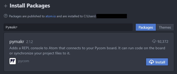
- In the Search Packages box, type in Pymakr and hit Enter, as shown in the following screenshot:
- Click on the Install button to install the Pymakr package.
- Since we will be writing LoRa code onto our LoPy/LoPy 4, it is a good idea to install the antenna pig tail and antenna to our LoPy/LoPy 4. Gently push the pig tail connector onto the uFL port on the LoPy/LoPy 4 (on the left side below the RGB LED) and screw the antenna into the other end of the pig tail. Be sure to take into account male and female connections when connecting the pig tail to your antenna. You will need to install an antenna that matches the frequency for your region (check for local regulations). Refer to the following photograph:

You can also refer to the following chart:
| Region | Frequency Band |
| Europe | 863 MHz to 870 MHz |
| Americas | 902 MHz to 928 MHz |
| Asia | 470 MHz to 510 MHz |
- Now connect the LoPy/LoPy 4 to your computer through a USB connection through either the Pycom expansion board or the FTDI USB to TTL serial connection. You should get a message indicating that your LoPy/LoPy 4 has connected in the REPL. If not, then click on the Connect Device button and select the port the LoPy/LoPy 4 is connected to.
- You should see a cursor in the REPL in the bottom panel. Type help() and hit Enter to verify that the LoPy/LoPy 4 is connected properly:

- Now, let's test the REPL using the built-in RGB LED. We will start by importing the pycom library. Type the following into the REPL and press Enter:
import pycom
- Turn off the default blinking blue LED with the following code:
pycom.hearbeat(False)
- Turn on the red LED by typing the following code:
pycom.rgbled(0xFF0000)
You should see the red LED turn on.
Now that we have connected the LoPy/LoPy 4 and ran some basic commands, it's time to wire up the temperature sensor and write the edge device application code.