Assemble the tools required for disassembly.
Properly fitting screwdrivers are critical. The best type for gunsmithing is the parallel screwdriver.
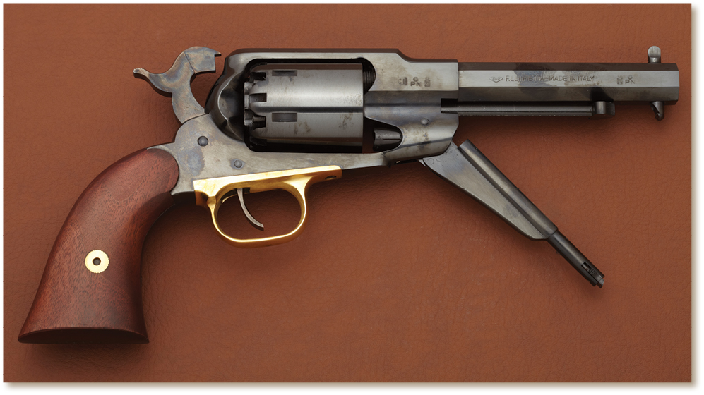
Pull back the hammer one “click.” This puts the pistol at half-cock and lowers the bolt, releasing the cylinder to rotate. Unlatch the loading lever and lower it halfway. Do not allow the plunger to contact the cylinder face.
The cylinder must be removed from the right side of the frame, so begin the disassembly with the muzzle pointing to the right.
With the gun at half-cock, start by pulling the cylinder pin toward the muzzle. This will release the cylinder and allow it to be removed from the frame. Reach under the left side of the frame and gently push up, while rotating the cylinder clockwise.

The rotation will cause the pawl to disengage from the ratchet star on the back of the cylinder, and the cylinder can then be lifted from the frame. The ratchet star is the set of triangular cuts between the nipples and the center pin hole. (Reinstalling the cylinder uses the same clockwise rotation, to allow the pawl to reengage the ratchet star.) The pistol is now broken down into the major assemblies. The following instructions cover detailed disassembly.

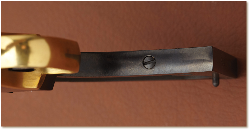
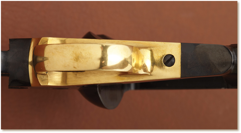
Turn the pistol over onto the other side and remove the loading lever screw, which is located above the channel through which the plunger moves. Pull the loading lever to the left to remove the lever and the plunger.
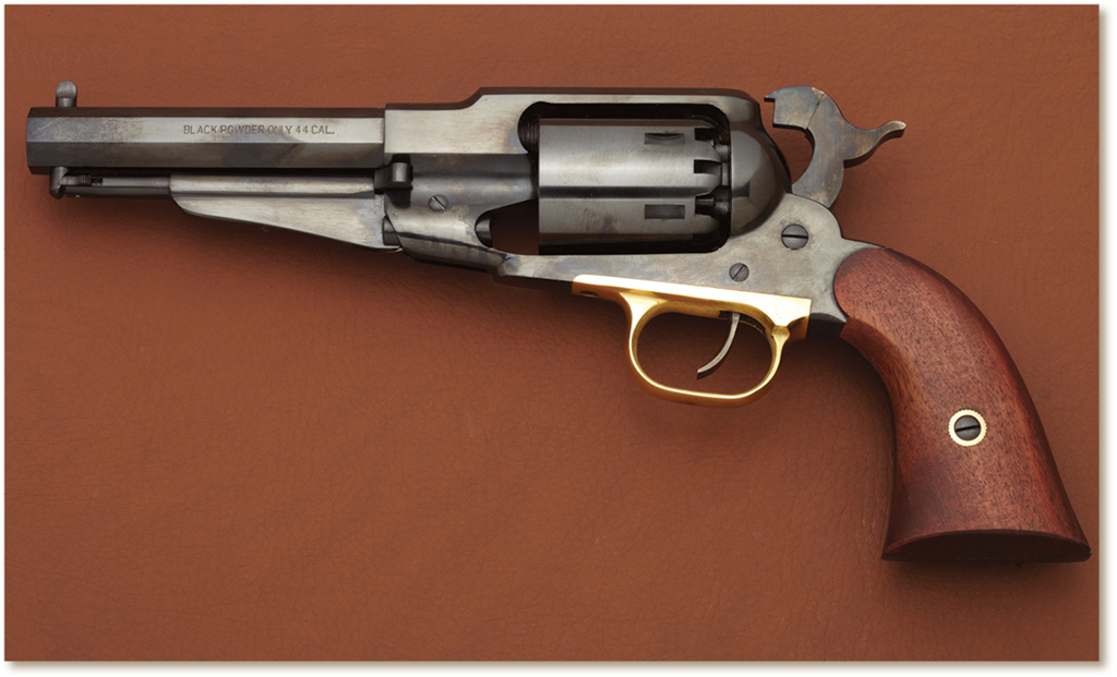
On the standard barrel length, the cylinder pin should now be pulled toward the muzzle and removed. The standard barrel length on the 1858 New Army is eight inches. The version pictured here has a 51⁄2-inch barrel. Note that the loading lever latch prevents the cylinder pin from being removed.
Refer back to the instructions for decocking a revolver before continuing. The rest of these instructions require mastery of this basic skill.

Remove the stock screw from the left-side stock panel and remove the stock panels from the grip frame. Unlike the Colt’s single-piece stocks, the Remington has two stock panels. The Remington frame does not have separate front- and backstraps, but the names are still applied to those sections of the frame in the same manner as on the Colt’s.
Loosen the main spring tension screw located on the frontstrap of the grip frame.
Remove the screw in front of the triggerguard and lift off the triggerguard.

The interior of the action is now exposed. Remove the trigger/bolt spring screw and lift off the spring.
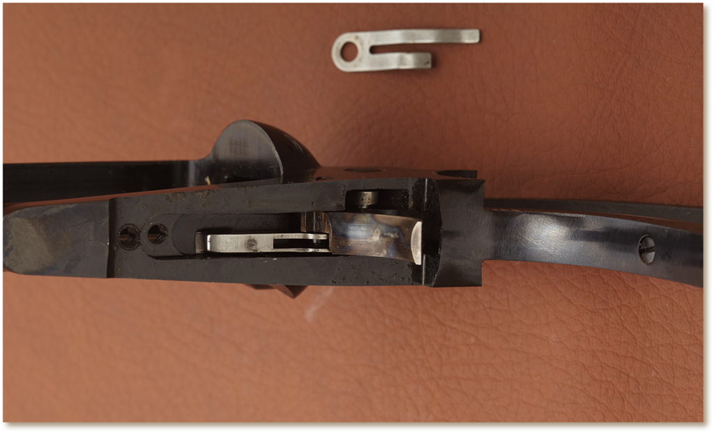


The two screws on the left side of the frame hold all the action parts. The smaller of the two is the trigger/bolt screw. The larger is the hammer screw. Before these can be removed, the main spring must be removed.
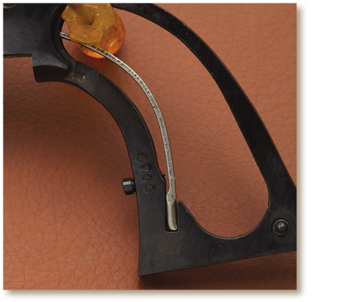
Bring the hammer back to full-cock to compress the main spring. Inset a block between the top of the main spring and the backstrap of the grip frame. In this photo, the handle of a small screwdriver was used for a block. Almost any solid material that is softer than steel will work as a block. Wood dowels are best.
Note: The main spring screw can be seen at the bottom of the photo. It has been loosened to relieve tension on the spring, making it easier to remove. The screw can be completely removed if desired, but this isn’t really necessary.

Use the decocking procedure described before to allow the hammer to move back to the normal resting position. Remove the trigger/bolt screw and withdraw the trigger and bolt from the bottom of the frame. Remove the hammer screw and pull the hammer up until it stops. It is not possible to remove the hammer until the pawl has been disconnected. Pulling up allows clearance for the removal of the main spring.
Slowly slide the block along the main spring toward the bottom of the grip frame, until it slips off the spring and can be removed. This should be a gentle movement. Do not allow the spring to “pop” up suddenly and strike the bottom of the hammer or the gun frame.
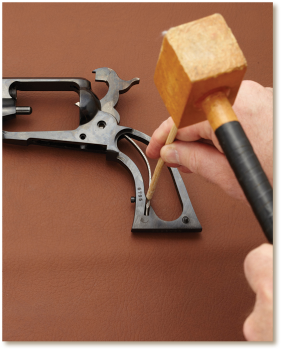
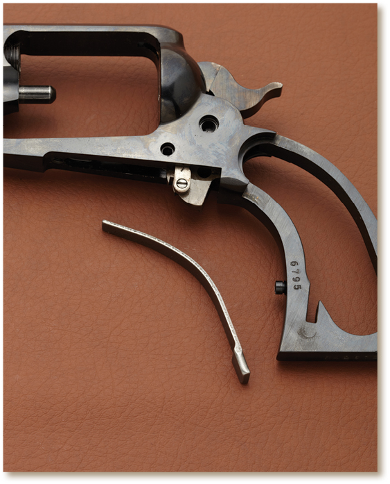
A small drift can now be applied, using the wooden mallet to tap the bottom of the main spring out if its slot. The main spring can now be removed.
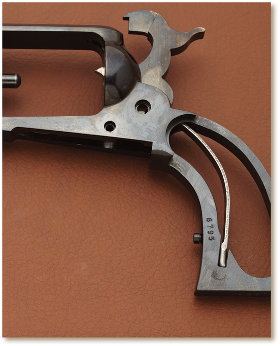
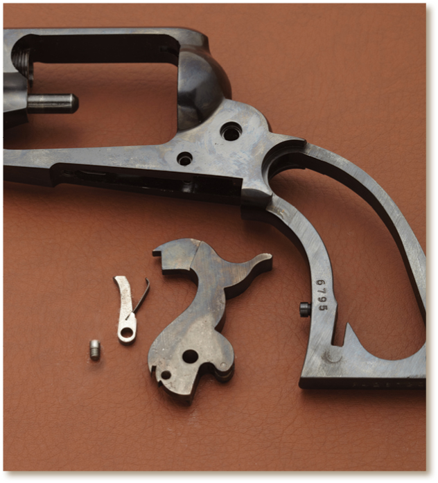
Push the top of the hammer down until it protrudes from the bottom of the frame. Remove the pawl screw, visible in this photo, and gently remove the hammer from the top of the frame. The pawl should be removed from the bottom, taking care not to damage the attached pawl spring.
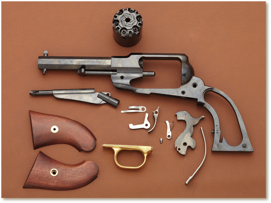
Detailed disassembly is now complete. Assembly is in reverse order.
Note: Reinstalling the main spring should begin by inserting the top into the frame first. Then, using the drift, put the bottom of the spring back into the slot. Once the bottom of the spring is installed, slide the block used during disassembly through the grip frame on top of the spring. Push the block as far as possible toward the top of the grip frame to compress the spring. This will allow the hammer screw to be installed, and the block can then be removed.