CHAPTER 1
ROOFING SYSTEMS
1. STARTING
POINTS FOR ROOF SYSTEM SELECTION. This Chapter is intended to introduce the
major considerations in selecting a roofing system. Figure 1 depicts the
various alternative roofing systems and how they relate. When commencing the
selection process there are two different starting points.
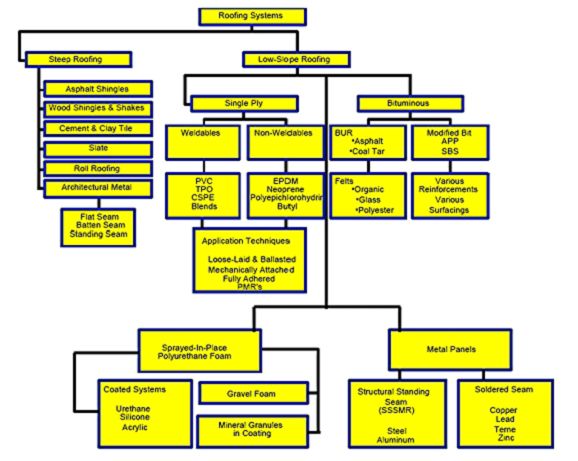
Material and Roofing System Options
Figure 1
1.1 New vs.
Reroofing. The roof may be part of a new building design; or, it may
involve the reroofing of an existing structure (replacement or re-cover).
Today, approximately 75% of roofing activity is reroofing.
1.2 Steep-Slope
vs. Low-Slope. In new construction the designer is very likely to have a preconceived
notion as to whether a highly visible sloped-roof is wanted, or whether
a less visible low-slope roof design is acceptable. Positive drainage is
a very important design criterion. When reroofing, it may be feasible to
improve drainage by using tapered insulation or sloped deck fills.
2. SELECTION
CONSIDERATIONS FOR STEEP ROOFING SYSTEMS. Table 1 evaluates common steep
roofing systems based upon some use criteria.
2.1 Aesthetics.
Steep roof systems make a strong visible statement about a building. The texture,
shadow-line, and color are major factors in selection.
2.2 Minimum
Slope Requirements. Steep roofs function by shedding water rather than by being
waterproof (Figure 2). Minimum slopes as shown in Table 13, are required in order
to insure proper drainage.
2.3 Categories
of Steep Roofing. Major categories of steep roofing include asphalt
shingles, wood shingles and shakes, tile, slate, architectural metal, asphalt
roll roofing, and fabricated units of metal or plastic intended to look like
the others. Only asphalt roll roofing and asphalt or wood shingles may be
re-covered.
2.4 Snowshedding
and Ventilation. Sloped roofs are effective snowshedders. In addition, the
attic space that accompanies steep roofing makes it easy to ventilate the
roofing system.
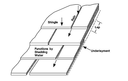
Steep Roofing (hydrokinetic)
Figure 2
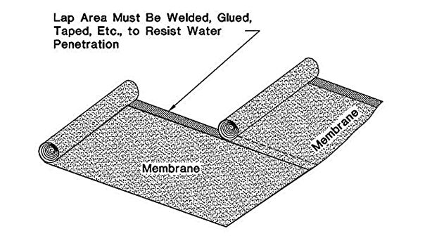
Low-Slope (hydrostatic)
Figure 3
2.5 Maintenance
Requirements. Sloped roofs in general, require less maintenance than flat roofing
systems.
2.6 Steep
Roof Conversions. When considering reroofing a flat roof, it may be
possible to convert the low-slope roofing system to a steeply sloped roof. This
may improve the appearance of the building while resolving drainage problems as
well. Steep roof conversions are a viable option for relatively narrow
buildings.
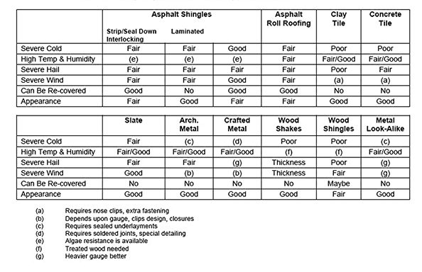
Steep Slope Selection Based Upon Use Criteria
Table 1
3. SELECTION
CONSIDERATIONS FOR LOW-SLOPE (MEMBRANE) ROOFING.
Membrane
roofing is typically used on commercial buildings where the minimum slopes
required by steep roofing render them impractical for larger buildings.
Low-slope membrane systems are completely sealed at laps and flashings (Figure 3)
and can temporarily resist standing water conditions. Choices for membrane
roofing include multi-ply bituminous built-up (BUR), polymer-modified bituminous
(MB), elastomeric single-ply systems (e.g., EPDM), thermoplastic single-ply systems
(e.g., PVC or TPO), sprayed-in-place polyurethane foam (SPF), and some metal (hydrostatic/low-slope/SSSMR)
systems. Designers frequently select low-slope roofs when the roof is expected
to accommodate rooftop equipment. With the exception of foam and metal, all low-slope
systems can be incorporated into Protected Membrane Roof (PMR) designs.
4. REROOFING
AND RE-COVERING.
4.1 Reroofing.
The term replacement is used when the existing roofing system is to be
either partially or totally removed and a new system installed. The designer
should consider any existing problems and whether drainage and thermal
performance needs to be improved. Existing surfaces such as walls and curbs
may be contaminated with bitumen, which might affect compatibility with some
reroofing options. Additional concerns (as compared to new roofing) include
whether the existing structure can handle a significantly heavier roof system
and whether construction activities of the reroof system will affect the
occupants of the building (i.e., fumes, falling debris, and noise).
4.2 Re-cover.
The term re-cover is used when a new roofing system is to be
superimposed directly over an existing system. In this case, underlying
conditions are obscured making assessment of their condition more difficult.
Additional concerns include how the re-cover system will be attached to the
existing membrane or roof deck, and compatibility with the substrate. The potential
for trapped water between the old and new membrane may suggest the use of
venting base sheets and/or roof vents.
5. ENVIRONMENTAL
ISSUES. A relatively new design criterion is whether the roof system under
consideration meets green criteria, such as whether the system
incorporates postconsumer waste or is itself recyclable at the end of its
useful life. Roof system waste is bulky and puts a great strain on waste
disposal sites. Energy efficiency is also important in terms of raw materials
acquired, production of finished goods, and application of the roof system.
Thermal performance in service and retention of thermal value with age are
equally important. A sustainable or robust roof is highly
desirable as extension of the life of the roof contributes to overall
conservation. High albedo (reflective) roofs may improve localized climate
conditions. The felt used in asphalt organic shingles consists primarily of
recycled wastepaper, wood chips, and sawdust. Asphalt itself is a by-product of
petroleum refining. Wood fiber and perlite roof insulation contain waste paper.
Glass fiber and asphalt organic shingles have been recycled into asphalt
curbing and the like. Wood shingles and shakes can be recycled into garden
mulch. Steel and aluminum contain recycled scrap and at the end of their life,
metal panels can be recycled back into scrap. Tables 2 and 3 compare
environmental considerations for steep and low-slope roofing systems.
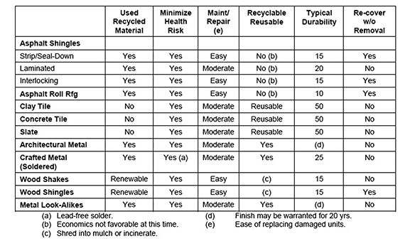
Preserving the Environment – Steep Roofing
Table 2
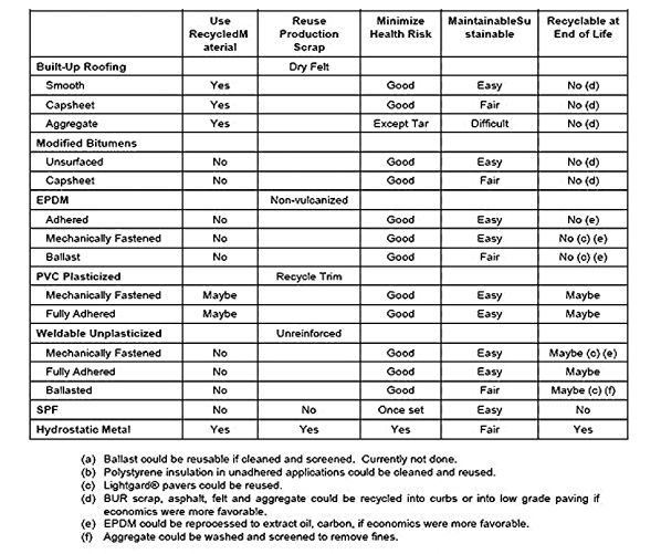
Preserving the Environment – Low-Slope Roofing
Table 3
6. DETAILED
INFORMATION. Once a tentative roofing system selection has been made using
information provided by this discussion.
7. USING
PRINCIPAL DESIGN CONSIDERATIONS TO REDUCE THE NUMBER OF POSSIBLE ROOF SYSTEMS.
7.1 Principal
Design Considerations. Tables 4 and 5 list some of the principal design considerations
in roof system selection. An explanation of the headings follows the tables.
These tables are not all-inclusive but contain many criteria that the designer
can consider to reduce the myriad of choices. Systems that fail to meet the
principal project design criteria can be quickly disqualified from further
consideration. For example, if an existing structure has reached its design
load limit, then heavier roofs (such as ballasted single-ply roofs or concrete
tiles) would have to be disqualified (or the structure would have to be
strengthened at significant cost).
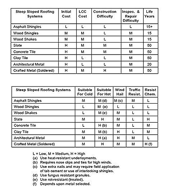
Principal Design Considerations—Steep Roofing
Table 4
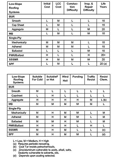
Principal Design Considerations—Low-Slope Roofing
Table 5
7.2 Discussion
of Headers in Tables 4 and 5.
7.2.1 Initial
Cost. This may include materials, labor, and special set-up for
construction.
Initial cost
may determine if the roof, as designed, is affordable. Perhaps a somewhat less expensive
system should be considered if it does not incur significantly increased maintenance
costs or have a shortened life.
7.2.2 Life
Cycle Cost. LCC considers durability but also presumes that routine
maintenance
will be performed to achieve the projected life. Consider whether the building
is temporary or permanent. It would be hard to justify an expensive copper or
slate roof on a building scheduled for demolition in the near future. Also
consider the mission of the building. There are levels of quality in many systems.
For example, while 45 mil EPDM is the standard, for little extra cost 90 mil
material with greater puncture resistance, or conversion to a PMR system, could
be specified for a building with a critical mission.
7.2.3 Construction
Difficulty. Some systems require more clearance to accommodate
application
methods and equipment. Large prefabricated roof sheets (i.e., 50 ft. by 200
ft.) may be fine on a large roof with few penetrations, but are impractical on
a roof area that is broken up by many curbs and equipment supports. On multiple
penetration surfaces, relatively narrow sheets (e.g., BUR, MB, thermoplastic
single-ply) or sprayed-in-place polyurethane foam should be considered.
Penetrations through standing seam metal roofing need to accommodate the
expected thermal movement of the metal panels. Thermal movement is cumulative, increasing
with distance from the point where the panels are restrained (typically the
eaves). Penetrations in SSSMR panels must pass through the flat portion of the
panel, not through the standing seam. Penetrations wider than a single panel require
a diverter to carry water around the obstruction. Water must flow parallel to
the raised seams, never over them.
7.2.4 Periodic
Maintenance—(The need for periodic maintenance and difficulty of
inspection
or maintenance.) Some roof systems require periodic recoating for weather
protection. Aggregate surfaced roofs are more difficult to inspect and patch
than smooth surfaced roofs.
7.2.5 Life
Expectancy. A mean life is listed but the actual life is affected by
drainage,
maintenance,
and extreme use or abuse.
7.2.6 Suitability
in Severe Cold. Effects of freeze-thaw, hail, ice scrubbing, and traffic
while cold (i.e., snow removal) is considered. Some materials embrittle
dramatically at low temperatures (i.e., have a relatively high glass transition
temperature); others may embrittle as they weather and lose plasticizer or are
degraded by UV or thermal load. H indicates highly suitable; L indicates
less suitable.
7.2.7 Suitability
in Extremely Hot or Humid Conditions. Effects of thermal expansion and algae
growth are considered. H indicates more suitable, L indicates
less suitable.
7.2.8 Wind
Resistance. Roofs are vulnerable to wind scour and blow-off. While
arbitrary ratings are provided here, the resistance is affected by building
height, terrain, parapet height and measures taken to upgrade perimeter and
corner attachment. H indicates highly wind resistant (when properly
designed). For membrane roofing, impermeable roof decks such as cast-in-place concrete
are best. Air retarders are needed with loose laid and mechanically fastened
single-ply systems as they may otherwise balloon from interior air leakage.
Perimeter wood blocking must be well anchored to prevent peeling of the
membrane or loss of fascia metal. Avoid the use of small aggregate (e.g., pea
gravel) near tarmacs and on skyscrapers due to the damage it can cause if blown
off the roof by high wind. Asphalt shingles may require manual application of
tab adhesive. Interlocking asphalt shingles provide excellent wind resistance.
Metal panel systems are wind resistant only when all components including
clips, fasteners, and secondary structural members are installed as
wind-tested. SPF has outstanding resistance to wind and to wind-blown missiles.
SPF roofs performed well in hurricane Andrew, especially when they were
spray-applied
directly to
concrete roof decks.
7.2.9 Resistance
to Ponding Water. Membrane roof systems rely upon sealed seams to resist
hydrostatic pressure. Water absorption may result in root or algae growth or
cause rot. H infers highly resistant to these conditions.
7.2.10 Traffic
Wear Resistance. Roofs that have a lot of rooftop equipment will have foot traffic
that can cause punctures or abrasion. Most roof systems are available with
traffic protective overlayers, such as walkways. H indicates highly
resistant to abuse assuming protective courses have been used.
7.2.11 Resistance
to Chemicals (resistance to oils, fats, grease, metal ions). Some roof surfaces
are vulnerable to exhausted fumes or liquids. Thermoplastic polyolefins (TPO’s)
and Hypalon® (CSPE) may be better than bituminous materials in resistance to
oils, greases, and solvents. Copper-containing runoff water from condensate
coils or flashings will corrode zinc and zinc-aluminum SSSMR roofing. H indicates
better than average resistance to attack.
7.3 Weight
Factor. Consider the total number of roofs already installed, the weight of
the proposed roof system possible, and construction loads. The unit weight of
membrane systems vary dramatically, ranging from less than 0.5 psf for a 2 in. thickness
of SPF, to more than 20 psf for ballasted single-ply systems. Typical roof
system weights and construction loads are shown in Table 6.
7.4 Compliance
with Fire & Wind Requirements. Roofing systems are rated as entire systems,
including the roof deck, method of attachment to the deck (e.g., fasteners, hot
bitumen, cold adhesives), vapor retarder (if used), thermal insulation, roof
membrane, and surfacing. Typical External Fire Ratings (ASTM E-108, Class A, B
or C) are shown in Tables 7 and 8. Combustible decks (wood/plywood/OSB)
require selected combinations of underlayments, insulation, roofing, and
surfacing to resist burning brands and intermittent flame as described in ASTM
E108.
7.5 Roof
Decking. Principle roof decks for membrane roofing include steel,
cast-in-place concrete, precast concrete, wood, plywood, OSB, and structural
wood fiber. Variations of cast-in-place concrete include lightweight structural
concrete (typically 1680 kg/m3)(105 psf) and lightweight insulating
concrete(480 kg/m3)(30 psf). In new design, the roof deck is generally selected
based upon construction considerations and materials. Steel is by far the most
popular, followed by concrete and plywood/OSB. Table 9 lists some criteria for
deck selection for new construction. Table 9 lists methods of attachment to the
roof deck. Attachment options include full adhesion, mechanical fastening, and
loose-laid/ballasted roofing. Steel decking requires a
bridging course
typically mechanically fastened roof insulation. For steep roofing, plywood and
OSB roof decks are most common. They generally utilize flexible batts as
underdeck roof insulation although architectural metal and cathedral ceiling
constructions may use rigid insulation above the deck.
7.6 Suitability
of the Membrane for the Substrate. Table 10 lists some possible
combinations.
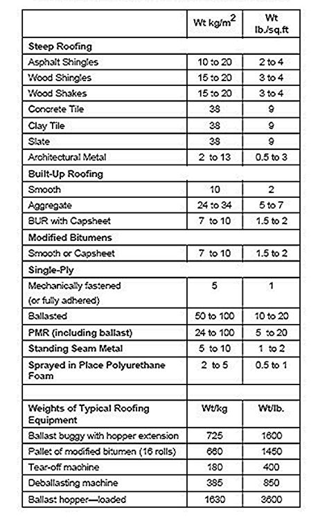
Typical Weights of Material and Equipment
Table 6
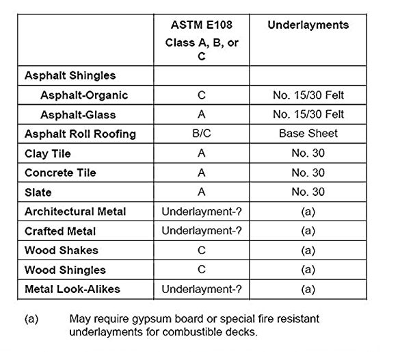
Fire Ratings and Required Underlayments for
Steep-Sloped Roof Systems
Table 7

Fire Ratings and Required Underlayments for Low-Slope
Roof Systems
Table 8
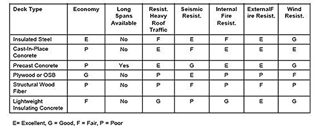
Suitability of the Roof Deck for Various Conditions
Table 9
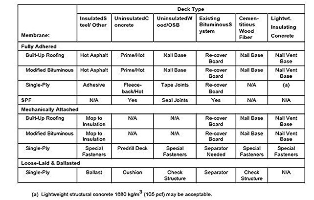
Membrane/Substrate Compatibility/Attachment Methods
Table 10
7.7 Thermal
Insulation. Rigid thermal insulations used under membrane roofing include
wood fiber, perlite fiber, glass fiber, foamed glass, polystyrene (extruded or
expanded), and polyisocyanurate (isoboards). Non-structural thermal insulations
include glass fiber and mineral wool batts, blown loose insulations such as
cellulose fiber, glass fiber, mineral fiber, and expanded vermiculite. Table 11
indicates suitability of rigid roof insulations for membrane roofing based upon
intended method of use.
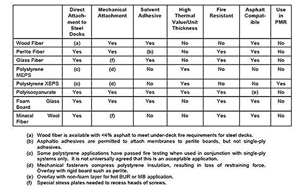
Suitability of Roof Insulation for Method of Use
Table 11
7.7.1 Thickness
of Insulation. If thick layers of insulation are needed to meet a high
therm resistance, thicker wood nailers and deeper fascia metal will be
required. Foam plastics such as polyisocyanurate and polystyrene have the
highest R values per unit thickness.
7.7.2 Clearance
of Metal Panels. In standing seam metal roof systems, the permissible
thickness of blanket insulation may be limited by the clearance provided by the
supporting clip design.
7.7.3 Insulated
Attic. Blanket insulation used in steep roofing systems is frequently
placed on the
floor of the attic where R-values of 30 (RSI = 5.4) or more may be possible (Figure
13).
7.7.4 Ceiling
Insulation. Dropped ceilings are sometimes insulated by placing batts
directly above
the ceiling panels. This practice is not recommended as subsequent access to underdeck
equipment or phone wires is blocked. When the insulation is displaced to gain
access it is rarely put back in place correctly, if at all.
7.8 Suitability
for Extreme Climates. Protected membrane systems (PMRs) are very well suited
to extremely cold climates and have been successfully used in all climates. For
extreme conditions of snow and ice, a cold (ventilated) roof should be
considered. For most steep roofing this is achieved by allowing a flow of outdoor
air between the insulation and the roofing system. This air cools the roof in
summer, dries out any moisture that condenses in the roof, and greatly reduces
the formation of icicles and ice dams along eaves. For regions prone to severe
hail, ballasted EPDM roofs are very good and PMRs are excellent. Tiles,
shingles, bare BUR, and metal systems are easily damaged by hail. In regions of
semitropical climate (high temperatures and humidity), asphalt shingles should
be treated to be fungus resistant and wood shakes/shingles should be pressure
treated for rot resistance.
7.9 Installation
in Cold or Wet Weather. Most membrane systems are difficult to install in subfreezing
weather. If frequent precipitation during construction is a problem, factory
fabricated single-ply systems with field welded seams may have advantages over
systems where field application of adhesives or hot bitumen is needed. Torch
applied modified bitumens are one of the few systems that can be applied,
albeit slowly, in wet windy conditions.
7.10 Warranties.
The NRCA Commercial Low-Slope Roofing Materials Guide contains a comprehensive
side-by-side comparison of commercial roof warranties. The roofing industry offers
two general types of warranties: Materials Only and Materials & Workmanship.
Carefully read exclusions and limits. Note: The longest warranties are not
necessarily the best, nor does the length of the warranty directly relate to
roof durability. In many cases, manufacturers may restrict their warranties.
7.11 Maintenance
Considerations. Sloped roofs require less routine maintenance and may be preferred
when the facilities management is incapable of providing routine inspections
and minor repairs. Modified bituminous and BUR systems may be superior in abuse
resistance to thin single-ply systems. Various protection boards/walkways can
be used around equipment where traffic is anticipated. Protected membrane roof
systems (PMR’s) are abuse resistant but more difficult to inspect and repair.
7.12 Roof
Access, Fumes and Property Protection When Reroofing.
7.12.1 Fumes.
In reroofing situations fumes from kettles and solvents may be objectionable.
Hot coal tar pitch is especially objectionable; hot asphalt is also noticeable
but less noxious. Cold applied systems with taped or welded seams and metal
roof systems generate few odors. It may be necessary to coordinate
air-conditioning shutdown to avoid taking fumes into the occupied building.
7.12.2 Ease
of Construction Access. If the area around the construction site is congested
it may make heating and hoisting of roofing materials difficult.
7.12.3 Specifying
Construction Procedures. Site access, material storage area, layout area,
building and landscape protection should be identified on drawings.
7.12.4 Safety
and Disturbance to Occupants. The presence of occupants, vehicles, and pedestrians
may be of concern. Reroofing is noisy. Dust and overspray may affect those
nearby.
7.13 Installation.
Roofing requires skilled installers. Qualified contractors and inspectors are more
likely to be available if the system is customarily used in the region. It
should be determined whether there are several manufacturer-approved installers
capable of bidding the work.
7.14 Owner
Preferences. Verify that the contemplated system is acceptable to the
owner, occupants, and maintenance personnel.
8. CONSIDERATIONS
WHEN SPECIFYING LOW-SLOPE (HYDROSTATIC) MEMBRANE ROOFING. With the
exception of SSSMR, membrane roofing requires a suitable roof deck. Most constructions
will also use thermal insulation. Vapor retarders are sometimes required to
protect the roofing system from attack by interior moisture.
8.1 Built-up
Roofing (BUR). BUR Consists of multiple reinforcements such as asphalt
treated glass or organic felt laminated together with hot-applied bitumen
(asphalt or coal tar pitch) or cold adhesives (Figure 4). Surfacings include
aggregate, coatings, capsheets, and sprayed roofing granules. A typical system
includes thermal insulation and may include a vapor retarder.
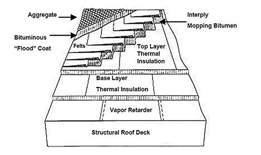
Typical BUR System
Figure 4
8.2 Polymer
Modified Bitumen. MB consists of reinforcing sheets factory-coated with
polymer modified bitumen. They may be laminated in the field using hot bitumen,
heat fusion, or by cold adhesives (Figure 5). Surfacings include capsheets with
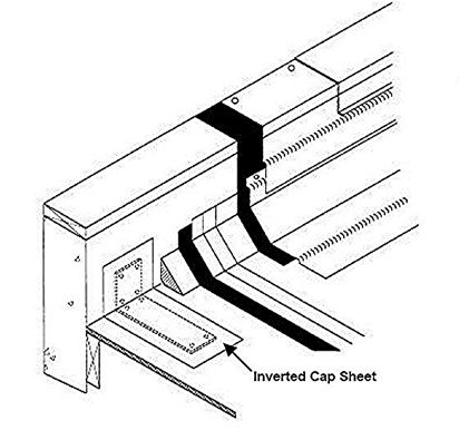
mineral granules, metal foil, and field applied coatings.
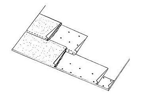
Polymer-Modified Cap Sheet Adhered to Mechanically
Fastened Base Sheet
Figure 5
8.3 Elastomeric
(Single-Ply) Membranes. Elastomeric membranes consist of a factory produced
sheet generally of EPDM rubber with seams field-sealed with adhesive or tape (Figure
6). Sheets are unsurfaced unless ballast is used. Elastomers are vulcanized
(thermoset), and usually non-reinforced except when used in mechanically
fastened systems. A fleece-backed sheet is also available for fully adhered
systems when it is desired to use hot bitumen as an adhesive (e.g., for
re-covering an asphalt-contaminated deck or old BUR).
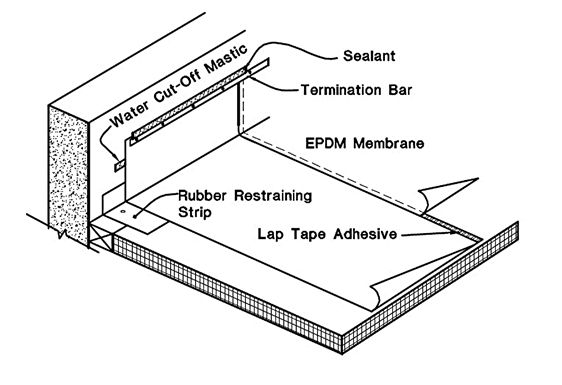
EPDM Roof System
Figure 6
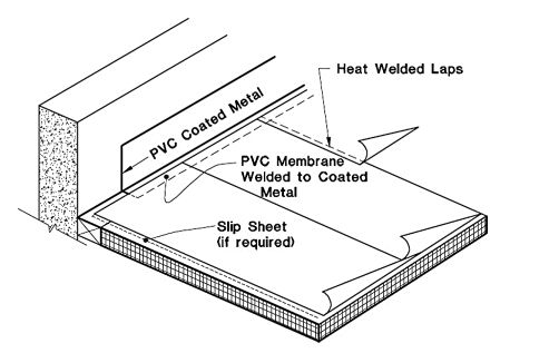
PVC Roof System
Figure 7
8.4 Weldable
Thermoplastic Membranes. These membranes consist of a sheet of reinforced thermoplastic
material such as PVC or TPO. Sheets are unsurfaced or ballasted. Seams are generally
heat fused although solvent welding and adhesive bonding are also possible (Figure
7).
8.5 Structural
Standing Seam Metal Roofing. SSSMR consists of metal panels with raised seams
more than 1-1/2 in. high (Figure 8). Sealants are utilized at side seams and endlaps
to provide waterproofing. Most are considered hydrostatic, resisting standing
snow and occasional ponding. Caution: ridges and valleys of a SSSMR may not be
as watertight as the seams.
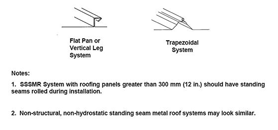
Structural Standing Seam Metal Roofing
Figure 8
8.6 Sprayed-in-Place
Polyurethane Foam. SPF is a thermoset rigid foam, field-formed by the reaction
of liquid components (in the presence of a foaming agent) sprayed onto the
substrate. SPF is protected by liquid-applied elastomeric coatings or an
application of loose gravel (on slopes < 4%).
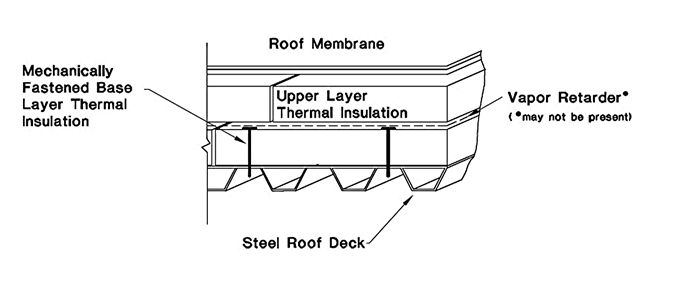
Components of Membrane Roofing System
Figure 9
8.7 Components
of Membrane Roofing Systems (Figure 9).
8.7.1 The
deck supports roofing loads and is selected to conform to fire resistant
design classifications. Not all systems require a deck (e.g., structural
standing seam metal roofing).
8.7.2 A
vapor retarder protects the insulation against moisture vapor attack from
the
warm, high
vapor pressure side of the roof assembly. Not all buildings require a vapor
retarder.
8.7.3 An
air barrier prevents air movement (infiltration or exfiltration) through
the roofing system.
8.7.4 Thermal
insulation provides thermal resistance and prevents condensation on
components
beneath the insulation. It also furnishes support and a smooth, continuous
substrate for the membrane.
8.7.5 The
membrane is intended to keep water out of the components below (as well as out
of the building). The membrane system affects fire resistance.
8.7.6 Individual
roofing components may be held in place by adhesives, fasteners, ballast, or
a combination of these methods.
8.7.7 Perimeter
flashings are waterproof vertical terminations of the membrane (perimeter
flashing) (Figure 10).
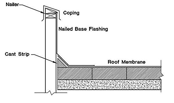
Wall Base and Cap Flashing
Figure 10
8.7.8 Roof
edging and fascia are usually low profile roof edge terminations and side
trim.
8.7.9 Roof
penetrations include drains, vents, curbs, equipment supports, and the
like.
8.7.10 Surfacing
materials screen UV light, improve fire ratings, and may improve water and/or
hail resistance.
8.8 Attachment
for Low-Slope Roof Systems.
8.8.1 Full
Anchorage. For relatively inelastic roof membranes such as BUR and MB,
solid adhesion helps restrain the roof membrane and uniformly distribute
thermal stresses. When insulation is used, it is fastened or adhered to the
deck. The membrane is fully adhered to the thermal insulation using hot asphalt
or cold adhesive. Polyurethane foam is sprayed directly to the substrate,
especially in re-cover of existing BUR thereby being fully adhered as well.
8.8.2 Partial
Attachment. In partially attached systems the membrane is mechanically
anchored
through the insulation into the deck, or in a few cases, partially adhered with
strips or spots of adhesive. This is common with flexible single-ply roof
membranes. Fasteners are typically placed in the seams area where by can be
covered by the overlapping sheet.
8.8.3 Loose-Laid
Attachment. For loose-laid systems the membrane is unattached to the substrate
and is held in place by ballast. Restraint is required only at perimeters and
curbs. Loose-laid roofs are used with elastomeric (EPDM) and some thermoplastic
(e.g., TPO) systems. These are very inexpensive roof systems if the
structure can handle the ballast weight.
Caution:
In positive pressure buildings air
barriers should be used with loose laid and partially attached membranes to
avoid billowing and peeling.
8.9 Labor.
8.9.1 Highly
Intensive: BUR, MB
8.9.2 Moderately
Intensive: SSSMR—The system is very unforgiving of installation defects.
8.9.3 Medium
Intensity: Fully adhered and mechanically fastened single-ply.
8.9.4 Low
Intensity: Spray Foam requires the smallest crew (but is the most machine
intensive and
weather sensitive).
8.10 Slope.
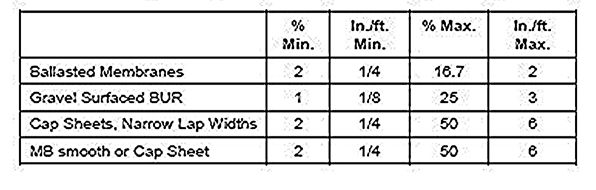
Some Typical Slope Limitations for Low-Slope Roof
Systems
Table 12
9. PRINCIPAL
CONSIDERATIONS WHEN SPECIFYING STEEP-SLOPE (WATERSHEDDING) ROOFING. This
category covers systems that range from asphalt shingles, wood shingles and
shakes, clay and concrete tile, slate, and metal look-a-likes. Also included
are architectural metal panels with a variety of seams (Figure 11). Slopes are generally
25% (3:12) or greater. Most must be continuously supported on a solid deck
(e.g., plywood or oriented strand board [OSB]). However, some varieties (e.g.,
clay and concrete tiles) may be supported on spaced horizontal batten boards. Underlayments
such as roofing felt, self-adhering MB or plastic film are usually required
over the entire roof to provide a secondary line of defense against driving
rain and blowing snow. In cold regions, a completely sealed MB underlayment is
needed along eaves, in valleys, and at dormers, skylights, chimneys and such to
resist leaks from water ponded behind ice dams.
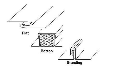
Architectural Metal Seams
Figure 11
9.1 Aesthetics.
By their very nature steep roofing is highly visible. Appearance may be of primary
concern to the designer. Regional preferences exist. For example, red tile
roofing is very common and highly desirable in the Southwest, while light gray
concrete tile is preferred in Florida. Wood shakes give a textured natural look
preferred in the Pacific Northwest.
9.2 Labor
Intensity and Labor Skill.
9.2.1 High
Intensity. Heavy brittle units of clay, tile or slate.
9.2.2 Medium
Intensity. Architectural metal, wood shakes.
9.2.3 Low
Intensity. Shingles.
9.3 Watershedding.
Steep roofs rely on gravity to cause water to flow away from headlaps. Recommended
minimum slopes are shown in Table 13. Lower slopes are sometime permissible by
increasing overlap or enhancing the waterproofness of the underlayment.
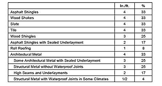
Minimum Slopes for Typical Steep Roofing Systems
Table 13
9.3.1 Valleys
and Eaves. Valleys must be well constructed. The slope of a valley will be less
than that of the intersecting planes that form it. Exterior drainage over the
roof edge or to a gutter is typical but may be troublesome in cold regions
since ice dams may form there.
9.3.2 Underlayments.
Sealed underlayments of self-adhering modified bitumen are typically used
along the eaves to at least 24” beyond the interior wall line (Figure 12a) and
as valley lining. Occasionally the entire roof deck is covered with such a
membrane. Note that this can lead to problems if indoor moisture is not
isolated from the roof by well made vapor and air barriers. Underlayments are
used in steep roofing as a secondary defense against water penetration (Figure 12b).
These include No. 15 felt, No. 30 felt, and self-adhering MB sheets. For
hydrokinetic and crafted metal, self-adhering MB sheets are essential as a
secondary water barrier.
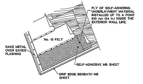
Self-Adhesive Eaves Flashing
(Underlayment is sealed from eave to 24” within wall
line.)
Figure 12a
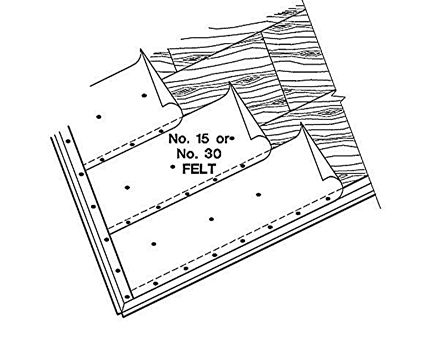
Underlayment for Steep Roofing
(Underlay felt is unsealed)
Figure 12b
9.3.3 Energy
Efficiency. Steep roofs generally cover an attic space (figure 2-13) (with
the exception of cathedral ceilings). The floor of an attic can be
inexpensively insulated with nonstructural insulations such as fiberglass
batts, mineral wool, expanded vermiculite, or treated cellulose. Where the
thickness of the insulation is not limited by clearance problems, very high thermal
resistances (e.g., Rsi > 5.56, R > 30) can be achieved. If a vapor
retarder is required for a cold arctic climate the retarder needs to be placed
on the interior (warm side) of the insulation. The attic space above this
insulation should be ventilated to remove moisture and to keep the attic
relatively cold; this minimizes ice damming at eaves.
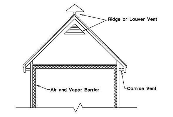
Vented Attic Space
Figure 13
9.3.4 Durability.
Mean durability of common steep roofing has been estimated in one survey as:
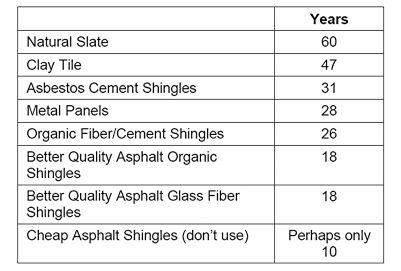
Mean Durability of Common Steep Roofing
Table 14
10. ADDITIONAL
CRITERIA AND DISCUSSION.
10.1 Wind. Maximum
wind speeds associated with locality and storm type determine needed resistance.
ANSI/ASCE 7-95 and EI01S010 provide design information.
10.1.1 Adhered
Systems. Air impermeable roof decks such as poured concrete, with adhered or
mechanically fastened insulation and fully adhered membranes, are highly wind resistant.
Tests conducted by the Factory Mutual System have determined that BUR systems installed
this way have resisted 8.6 kilopascals (180 psf).
10.1.2 Metal
Panel Systems. Metal panels are generally rated by the Underwriters 580 procedure,
with UL 90 ratings considered excellent. However, because some SSSMR panel systems
with UL 90 ratings have failed in service, structural standing seam metal roof
systems must pass the ASTM E1592 test method.
10.1.3 Ballasted
Systems. Ballasted single-ply systems rely on heavier and larger ballast in
more wind prone exposures. SPRI has developed wind guidelines in their
ANSI-SPRI RP-4 document based upon ANSI/ASCE 7-95 guidelines. Higher parapets
have a beneficial effect on ballasted systems. Above certain building heights,
SPRI recommends against the use of ballast.
10.1.4 Mechanically
Fastened Systems. Mechanically fastened single-ply systems use narrower
starter sheets and increased fastener density in high wind areas. Examples of
layout can be found in Factory Mutual Loss Prevention Data Sheet 1-29.
10.1.5 Foam
Systems. Sprayed-in-Place Polyurethane Foam (SPF) systems have proven very
wind resistant and are effective in protecting the structure against wind
hurled missiles.
10.1.6 Problems
with Small Roof Aggregate. Roofs adjacent to airport tarmac activities should
avoid aggregate surfacing as loose aggregate may be blown off the roof and
sucked into engines. Loose stone ballast which is much larger, is used
successfully at many airports.
10.1.7 Wind
Rated Roofs. Underwriters Laboratories lists wind rated systems in their Roofing
Materials and Systems Directory as Class 30, 60 or 90. Factory Mutual Research Corporation
lists wind rated systems in their Approval Guide with ratings ranging
from 60 to 210 psf.
10.1.8 Steep
Roofing. For most steep roofing systems, additional fastening is required
for
high wind areas
(e.g., six fasteners per asphalt shingle instead of four, addition of nose
clips for tiles, etc.).
10.2 Ice
and Hail. The formation of ice can cause the roof membrane to split. Ice
can also affect roofing performance by scrubbing the membrane and eroding the
surface. This can be especially detrimental to materials with a relatively high
glass transition temperature (Tg). Bituminous materials have a Tg of
approximately 32°F. Modified bituminous materials with an SBS modifier can have
a Tg as low as minus -30°F. EPDM membranes report a Tg less than -40°F. The Tg
of thermoplastics may increase with age (i.e., loss of plasticizer in PVC). Ponding
promotes ice damage; drainage avoids it.
10.2.1 Impact
Damage. Falling ice, such as from overhead towers, causes impact damage. Ballasted
EPDM provides some protection. Protected membrane roofs in which both
polystyrene insulation and ballast are placed over the finished roof membrane
provide excellent impact resistance.
10.2.2 Perimeter
Icing. Ice formation at eaves, scuppers, and gutters is a major design concern.
For low-slope roofing selection of internal drainage where building heat keeps
the drain lines unfrozen is recommended.
10.2.3 Minimizing
Icing Problems. For metal and steep roofing heating cables are sometimes
necessary but not especially reliable. In cold regions use of a cold roof in
which the roof is ventilated to prevent formation of icicles and ice dams is
preferred. Self-adhering waterproof membranes are needed to avoid leaks from
ice damming (Figure 10).
10.2.4 Hail
Damage. Weather maps are available that generally divide the U.S. into regions
that require resistance to severe hail (2 in. dia.), moderate hail (1-1/2 in.
dia.), and areas of low hail probability. Hail resistance is affected by the
compressive strength of the substrate, thickness of the membrane, tensile
strength, and age/brittleness of the material.
10.3 Snow.
Snow removal operations in which shovels or snow blowers are used can cause
severe damage especially to cold, brittle membranes. Smooth single-ply
membranes and metal roofing are extremely slippery when wet or when a thin ice
film covers melt water. Roof walkways consisting of compatible materials are
essential when it is necessary to walk on wet or frozen roofs.
10.3.1 Metal
Roofs. TI 809-52 recommends that SSSMRs should have a minimum slope of 8.3%
in cold regions.
10.3.2 Snow
Loads. Snow load information is available in ANSI/ASCE 7-95, TI 809-01, and
TI 809-52.
10.4 Slope.
Drainage is essential on all roofing systems. For hydrokinetic roofing the
drainage must be positive and rapid. Shingles, tiles, and the like,
generally have industry minimum recommended slopes of 33% to 42%. Sometimes
a lower slope option is available if waterproof underlayments are used.
10.4.1 Metal
Roofs. Minimum slopes for metal roofs vary from 4% to 33%, depending upon roof
type.
10.4.2 Membrane
Slope. Low-slope membranes should also comply with a minimum slope of 2%
(1/4 in./ft.). Where ponding is unavoidable such as in spray ponds, a BUR with
double poured aggregate and bitumen is sometimes used. Coal tar pitch membranes
are used at slopes as low as dead level and to a maximum slope of 2% (1/4
in/ft.). drainage is also needed. However, small puddles are inevitable as SPF
is never completely smooth. Small puddles should dry out within 24-48 hours after
inclement weather. Additional elastomeric coating is recommended where ponding
is anticipated.
10.4.3 Foam
Slope. For Sprayed-in-Place Polyurethane Foam (SPF) systems positive drainage
is also needed. However, small puddles are inevitable as SPF is never
completely smooth. Small puddles should dry out within 24-48 hours after
inclement weather. Additional elastomeric coating is recommended where ponding
is anticipated.
10.4.4 Reroofing.
In reroofing and re-covering applications, correcting the slope to 2% (1/4 in./ft.)
is sometimes unfeasible because of low windows, flashings, etc. In these cases,
tapered insulation at 1.5% (3/16 in./ft.) slope may be an acceptable
compromise.
10.4.5 Steep
Roof Conversion. Conversion of a poorly draining roof to a steep roofing system
may be accomplished on a relatively narrow roof system building by installing
new sloped joists.
10.5 Vapor,
Humidity, Moisture and Condensation. Moisture can be carried through
materials by diffusion or by the movement of air. Air barriers are needed to
reduce air movement. They can be located anywhere within the building envelope.
Vapor retarders, when needed, must be placed within the warm portion of the
thermal insulation.
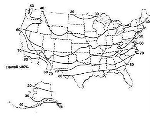
10.5.1
Self-Drying Systems. In cold weather, warm moist indoor air driven from
within the building towards the colder exterior may accumulate during the
winter then dry back out again during the summer months. Guidelines for the use
of vapor retarders in roofs are presented in CRREL Misc. Paper 2489, Vapor
Retarders for Membrane Roofing Systems. Figure 14a indicates suggested
maximum allowable relative humidities where summer dry-out should be adequate. Figure
14b is used to adjust Figure 14a for temperatures other than 60oF.
10.5.2 Reverse
Vapor Drive. For hot humid climates a reverse vapor drive may occur especially
in cooler and freezer buildings. In this case the membrane and wall retarder
sealed and continuous. Roof vents and breathing edge details must be avoided.
For freezer buildings, consider separating the roof system from the freezer.
10.5.3 High
Humidity Occupancies. For buildings with high interior relative humidity including
bakeries, laundries, pools, kitchens, dining halls with serving lines and the
like, vapor retarders are considered essential.
Interior Relative Humidities (%) with Interior
Temperature of 68oF)
Figure 14a
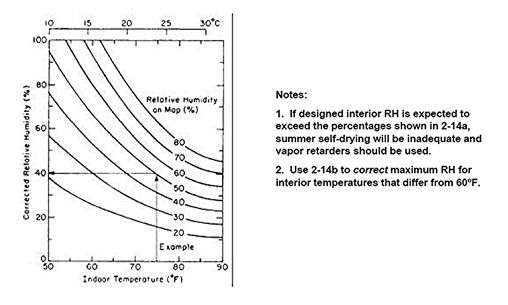
Temperature Conversion When Temperatures Differ from 68o
F
Figure 14b
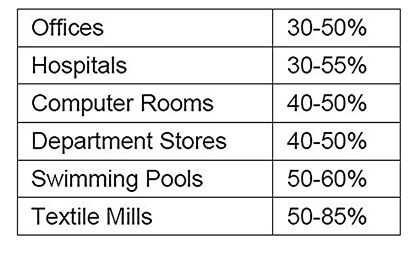
Typical Indoor Relative Humidity in Winter
Table 15
10.5.4 Bituminous
Vapor Retarders. Bituminous retarders are installed over solid fire barrier
substrates such as concrete, gypsum board, or a fire resistant insulation. Bituminous
retarders have near zero perm ratings. For most membrane roofing systems vapor
retarder permeance should be below 0.5 perms (28.6 ng/s•sq m•Pa). Perm ratings
for various vapor retarder materials can be found in the ASHRAE Handbook of
Fundamentals as well as in industry literature.
10.5.5 Non-bituminous
Vapor Retarders. Non-bituminous single-ply systems may use plastic films as
vapor retarders. These can be successful if the seams and penetrations are carefully
sealed with tape. Puncturing the retarder, either accidentally or by installing
mechanical fasteners lessens its resistance to moisture.
10.5.6 PMRs.
Protected Membrane Roofing systems (PMR’s) are very effective against vapor
drive from within the building. The roof membrane itself serves as the vapor
retarder as most, if not all, of the thermal insulation is located above it.
Self-drying of the insulation (extruded polystyrene) to the atmosphere
maintains the thermal resistance.
10.5.7 SPF
Systems. SPF systems are commonly installed on re-cover installations where
the old
bituminous membrane can be sealed to form a retarder. Dew point calculations
are necessary to insure the dew point is within the upper SPF layer.
10.5.8 Steep
Roofing. In steep roofing systems the retarder is usually a plastic film
(poly), treated kraft paper or foil facing on batt insulation installed with
the retarder facing the interior. When an attic or cathedral ceiling is
present, ventilation of the space above the insulation is essential since
retarders are rarely completely sealed and some moisture accumulation would otherwise
occur. Most codes recommend at least 1:150 net free ventilation area (total at
eave and ridge) when a retarder is not installed to 1:300 when a retarder is in
place. In cathedral ceiling construction larger net free areas are needed since
friction losses in the narrow airway reduce ventilation.
10.5.9 Metal
Systems. In structural metal systems where draped batt insulation is
used, it is
difficult to completely seal the retarder facer even if tape is used. When high
interior vapor conditions exist the use of a subdeck to support a retarder film
may be necessary. Other roofing systems should also be considered as such
systems are not good at resisting high internal relative humidities.
10.6 Considerations
When Using Thermal Insulation. Thermal insulation is important in modern
buildings both for energy conservation and human comfort and may impact roof membrane
performance.
10.6.1 Thermal
Resistance. Resistance to heat flow through the entire roof structure (characterized
by the R factor) should be as high as is both practicable and cost effective.
In general an R factor of > 20 (Rsi > 3.57) is recommended. Note: U = 1/R
therefore, the
U factor should be < 0.05 Btu/hr•ft2 oF.
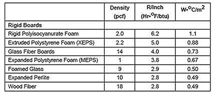
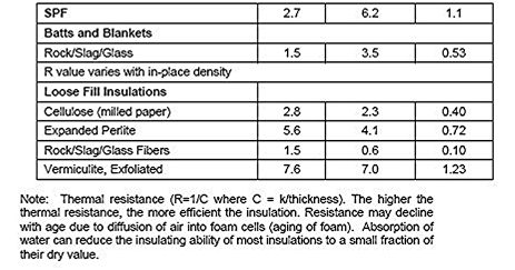
Unit Resistances (i.e., Resistivity) of Common Roof
Insulations
Table 16
10.6.2 Installation
Locations. Thermal insulation may be installed in four locations.
10.6.2.1 Underdeck
insulation (Figure 15).
- Wood frame
structures with steep roofing often utilize batt insulation placed between
the rafters. Vapor retarders of foil, kraft, or plastic film are located
on the inside face of the insulation. With structural standing seam metal
systems, batts are draped over the purlins. In attics, the insulation is
usually positioned between ceiling joists.
- An advantage
of underdeck insulation is that inexpensive nonstructural insulations such
as batts may be used.
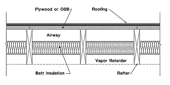
Under Deck Insulation
Figure 2-15
- A
disadvantage is that the roof deck suffers greater thermal stress than
when it is overlaid with insulation. Another disadvantage is that it is
difficult to vapor seal such construction and make it resist air
exfiltration and as a result moisture problems are prone to occur.
Ventilation is usually required but ventilating low-slope framed roofs
lacking tight air barriers is apt to increase moisture problems, not
eliminate them.
- Common
underdeck materials include compressible batts of glass fiber and mineral
wool. Thermal spacers of rigid plastic foam are placed over the purlins of
SSSMR systems to maintain the thermal resistance where the batts are
compressed.
10.6.2.2 Self-insulating
roof deck (Figure 16):
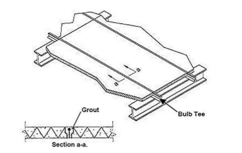
Self-Insulating Roof Deck
Figure 16
- Insulating
decks such as structural wood fiber are less popular today because it is
difficult to achieve high R values within the deck itself. In reroofing
situations supplemental insulation would often be added on top of such a
deck. In some new assemblies a composite of structural wood fiber topped
with plastic foam is used. The underside of these self-insulating decks
can be exposed to the interior and serves as an attractive acoustical
ceiling.
10.6.2.3 Thermal
insulation within the roofing sandwich (Figure 9).
- Insulation on
top of the roof deck is the most common configuration for membrane
roofing. For adhered membrane systems the thermal insulation restrains the
membrane against wind loss or shrinkage and must have adequate structural
strength. For mechanically anchored and ballasted systems compressive
strength and stability are important. If hot asphalt or solvents are used
in construction of the membrane, the insulation must resist degradation by
these agents.
- Common
materials for adhered systems include faced polyisocyanurate foam
(ASTM C1289), perlite (ASTM C728), rigid glass fiber boards (ASTM C726),
wood fiber (ASTM C208), and cellular glass (ASTM C552). Verify that the
combination of membrane and roof insulation/facer are Fire and Wind Rated.
- For
mechanically fastened and ballasted systems expanded and extruded polystyrene
(ASTM C578) are added to the above list. (They could melt or dissolve if
placed in contact with hot bitumen or solvent-based adhesives).
- Some decay of
R value is observed with HCFC blown foams (urethanes and
isoboards) due to diffusion of air and moisture into the cells of the
foam. Manufacturers publish aged R values to reflect this decay. Always used
aged R-values for these materials. Since diffusion starts at the surface of the
foam, thicker foams are more thermally stable.
- Wood fiber
boards should be manufactured to use as roof insulation (meeting
ASTM C208), not sheathing boards, and should be limited to 4 ft. in length
and width.
- When
mechanical fasteners are used to secure thermal insulation, it is recommended
that the nail-one, mop-one technique be used. This minimizes a thermal
bridging and avoids nail-popping of the membrane. When multiple layers of
insulation are used, vertical joints should be offset to reduce heat
losses. Straight-through joints can take away 10% of a roof’s insulating
ability.
10.6.2.4 Protected
membrane systems (Figure 17).
- In PMR
systems only extruded polystyrene is suitable in the sometimes wet environment
above the completed roof membrane. This insulation protects the membrane
from thermal stress and abuse.
- Ballast and
filter fabric is needed to hold the loose-laid insulation in place.
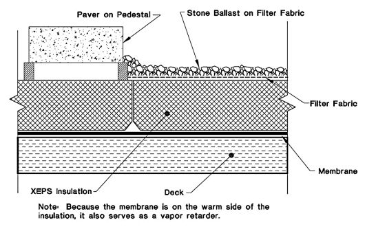
Protected Roof Membrane System (PMR)
Figure 17
10.7 Energy
and Solar Radiation. The ratio of roof area on a low-rise commercial
building is high relative to wall area. Such roofs can provide a great
opportunity for energy conservation. This can be accomplished by using well
insulated, high thermal mass structures to reduce summer cooling loads, garden
roofs, or high albedo roof coatings.
10.7.1 Heat
Gain. For roofs in hot or temperate climates, light colored roof surfaces
reduce heat gain. For membrane roof systems, light colored aggregate (gravel surfaced
roofs) or mineral granules (capsheets [ASTM D249, D371, D3909] and MB capsheets
[ASTM D6162, D6163, D6164, D6222, D6223]) will reduce heat maximum surface
temperatures by up to 35°F over black membranes. Aluminum coatings (ASTM D2824)
are approximately the same, while white coatings (ASTM D6083) have been
observed to reduce temperatures by more than 45°F (provided that the roof stays
clean). The use of pavers and heavy ballast reduce heat gain through thermal
lag; that is, the high heat capacity stores some of the gained heat delaying
the startup of the building’s air conditioning system. The ASHRAE Handbook
of Fundamentals uses the term Equivalent Temperature Difference (ETD) in
energy calculations. The smaller the ETD, the better the system is at reducing
peak solar loads.
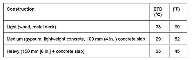
Equivalent Temperature Difference
Table 2-17
reflective roof
surfacing materials (e.g., white granules on shingles). Radiant barriers (reflective
foils) placed in attics are also effective.
10.8 Fire
Considerations.
10.8.1 Topside
Fire Ratings. Because of its large surface area, roofing plays an important
role in fire protection. Fire hazards can be defined as:
10.8.1.1
External, where the source is outside the building such as from wind blown flaming
debris. Tests for external fire resistance are referred to in building codes as
Class A, B and C.
- An external
fire rating is established by constructing and testing roofing assemblies
by methods described in ASTM procedure E108 (also known as UL790). In this
method relative degrees of fire resistance are established.
o Class A roof
coverings are effective against severe fire exposures. Under such exposures
roof coverings of this class are not readily flammable and do not carry or communicate
fire; afford a fairly high degree of fire protection to the roof deck; do not
slip from position; possess no flying brand hazard; and, do not require
frequent repairs in order to maintain their fire-resistant properties.
o Class B roof
coverings are effective against moderate fire exposures. Under such exposures
roof coverings of this class are not readily flammable and do not readily carry
or communicate fire; afford a moderate degree of fire protection to the roof
deck; do not slip from position; possess no flying brand hazard; but, may require
infrequent repairs in order to maintain their fire-resistant properties.
o Class C roof
coverings are effective against light fire exposures. Under such exposures roof
coverings of this class are not readily flammable and do not readily carry or communicate
fire; afford some degree of fire protection to the roof deck; do not slip from
position; possess no flying brand hazard; and, may require occasional repairs
or renewals in order to maintain their fire-resistant properties.
- Class A does
not mean Grade A! Note: In this classification only fire performance
is considered. A specifier should select the degree of fire resistance
required but recognize that selecting a higher rating does not assure
better waterproofing nor longer life. In fact, some compromise in
durability may have been made to meet the higher fire rating.
- ASTM E108
fire tests may be conducted on steep roofing, membrane roofing, SPF, and
metal panels. Listings of systems that meet these requirements are found
in the Underwriters Laboratories Roofing Materials and Systems
Directory, the Factory Mutual
- Approval
Guide, and reports/directories published by several other qualified
testing agencies.
o If a roofing
assembly fails to meet burn-through requirements of ASTM
E108 it may still be listed for use with non-combustible decks such as
steel, concrete, and gypsum.
o Roofing
assemblies are listed at the maximum incline to which the rating applies. As
long as the structure under consideration is at a lower or equal incline to
that listed it complies with the fire rating.
o If a listing is
intended for use as a roof superimposed over an existing roof, it should be
listed in the UL Roofing Materials and Systems Directory under the
category Maintenance and Repair Systems. In the FM Approval Guide it
will be listed as a Re-cover.
o In general,
only the materials listed qualify and only when used in the manner described in
the directories. Additional insulation, for example, might worsen the flame spread.
10.8.1.2 An
internal (underdeck) fire is when the flame spread is underneath the roof
deck. Listings
are referred to by the Approval Rating, usually Factory Mutual Class 1 or
Underwriters
Laboratories Insulated Metal Deck or Non-metallic Decks Constructions.
- Background—In
1953, a large insulated steel roof deck building suffered an unexpected,
catastrophic fire loss due to an underdeck fire exposure. The roofing
components above the deck contributed fuel to spread the fire. Tests
conducted on full scale test buildings confirmed the hazard. In the late
1950’s, laboratory tests were established and correlated to the full scale
data. Factory Mutual uses a calorimeter to establish fire performance
while Underwriters Laboratories uses a modified Steiner Tunnel test.
Successful systems are listed by FM as Class 1 while Underwriters lists
them as either Rated Metal Deck or Rated Non-Metallic Assemblies.
- The
underdeck ratings do not assure zero risk. The ratings assume an acceptable
risk assuming normal fire detection and fire control procedures are
available. If an insulated steel deck system fails to comply with the
requirements of FM Class 1, it is designated Class 2. Class 2
constructions may be converted to Class 1 by the addition of underdeck fireproofing.
Class 2 constructions may also be acceptable if an approved sprinkler
system is used.
- Fire
endurance tests. These are time-temperature tests (ASTM E119) in which
the roof-ceiling assembly is subjected to a rising heat load until either
the interior structural elements yield, or the temperature on the exterior
roof system reaches 139oC (250oF) above the ambient.
o The minimum
elapsed time required before the end point is reached is
usually established by building code or occupancy (e.g., 1-hour, 1-1/2
hour, etc.).
o Rated
assemblies are listed by UL in their Fire Resistance Directory and by FM
in their Approval Guide. Other testing agencies list rated assemblies in
their directories as well.
·
Assure that fire compliance (ratings) pertain to the entire
assembly. Each component of the system must be listed in the above directories.
Materials delivered to the job site should bear labels indicating compliance
with the construction intended. The label also provides third party assurance
that the products delivered to the construction site are essentially unchanged
from those tested and listed.
10.9 Seismic
Requirements. While membrane roofing materials in general do not affect seismic
stability of a structure, components of the roof system may be important. Roof
decks, for example, usually serve as a diaphragm increasing lateral stability.
10.9.1 Bracing
for SSSMRs. Structural metal systems with floating clips require bracing since
the structural standing seam metal panels do not provide diaphragm action. An
alternative to bracing is to use a steel subdeck to serve as the shear
diaphragm.
10.9.2 Inertia
Effect. Heavy roofing materials such as ballast or pavers may result in an inertia
effect that should be included in the design. This may be beneficial or
detrimental.
10.9.3 Lateral
Motion of Tiles. In steep roofing, seismic motion may shatter materials
such as cement and clay tile. Correct use of mechanical anchors may prevent
damage. Twisted wire systems are recommended for earthquake zones. The National
Tile Roofing Manufacturers Association requires two nails or a nail and a clip
on every tile to resist seismic damage.
10.9.4 Restraining
Roof Tiles. IR-32-1 (9/89), a Title 24 California code addresses the attachment
of tile, and allows the combination of wire tie and nose clips (wind locks or
tile locks). Nails or wire ties are to be copper, brass, or stainless steel 11
ga. minimum with two per tile. Nails are to penetrate roof sheathing, battens,
or support members 3/4 in. min. Ring shanked nails may be used when sheathing
thickness is less than 3/4 in.
10.9.5 Parapet
Walls. Parapet walls must be used with care. Through-wall flashings or
cut reglets
must be avoided as they reduce the wall’s resistance to lateral forces.
10.9.6 Roofing
Over Seismic Straps. Seismic straps (heavy metal plates) are sometimes installed
over plywood roof decks and between decks and walls. Where roof insulation is
not used (i.e., west coast capsheet construction), use construction details
provided by the Western States Roofing Contractors Association on how to roof
over the straps (Figure 18).
Roofing Over Thick Seismic Strap
Figure 18
10.10 Adequate
Design Details. Complete sectional views of every location where the roof changes
plane or there is a roof penetration or attachment should be provided on
contract drawings. Sections and design details should be drawn to a legible
scale with each element of the roofing system identified.
CHAPTER
2
COATINGS
AND PAINTS
1.
SELECTION OF COATINGS
1.1
Selection Criteria. The best selection of a coating system for a particular
service is determined by a variety of factors. These include desired
properties, work requirements and
limitations,
safety and environmental restrictions, compatibilities, and costs.
1.1.1
Desired Film Properties. In selecting a coating system, the first
consideration is the desired properties of the system for the particular
service. Desired properties may include one or more of the following aspects:
- Resistance
to exterior weathering (chalking; color and gloss retention)
- Water,
fuel, or chemical resistance
- Abrasion,
heat or mildew resistance
- Appearance
(color, gloss, and texture)
- Drying
time
- Ease
of application and maintenance
1.1.2
Work Requirements or Limitations. The following work requirements or
limitations may have to be considered:
- Type
of surface preparation
- Access
to work
- Drying
times
- Necessary
applicator skills
- Necessary
equipment
- Scaffolding
for access to work
1.1.3
Safety and Environmental Restrictions. It will be necessary to conform to
all prevailing safety and environmental regulations concerning materials and
processes to be used for surface preparation and for coating application.
1.1.4
Compatibilities. Coating systems must be compatible with the surfaces to
which they are applied. Coating incompatibility can cause failures at or just
after application or after a much longer time. Failures occurring just after
application are due to solvent incompatibility or wetting problems. Failures
associated with slow chemical reactions, such as those occurring between alkaline
surfaces (e.g., concrete and galvanized steel) and oil-based paints or
mechanical property mismatches (e.g., a rigid coating applied over a more
flexible one) cause failure in a longer timeframe. The failure more often is
peeling. For existing coatings being repainted, compatibility generally means
that topcoats should be of the same generic type or curing mechanism as
undercoats. One exception to this rule is inorganic zinc coatings. Since
inorganic zinc coatings frequently do not bond well to themselves, it is safest
to repair them with zinc-rich organic coatings. A simple test to classify
coatings is to determine solvent sensitivity using an methylethyl ketone (MEK)
or acetone rub test. To do this, soak a cloth in MEK or acetone, rub it against
the existing paint, and visually check for pick up of paint. The paint is
classified as "solvent soluble" if paint is picked up, and as
"solvent insoluble" if not. Another practical method of ensuring
topcoat solvent compatibility is to coat a small test area of the existing
coating with the paint selected for the work. If situations permit, this test
is preferred over the MEK rub test because it is specific for the surface to be
repainted. The test area should be visually inspected the following day (or
preferably after 3 or more days) for bleeding of undercoat, wrinkling, loss of
adhesion, or other coating defects. Although most incompatibility problems are
apparent in a couple of days, some types of incompatibility may not become
apparent for several months or until after a change of seasons. These types are
usually associated with mechanical film properties.
1.1.5
Costs. Life cycle cost has always been one of the most important
considerations in selection of coating systems. Life cycle costs include
original surface preparation, materials, and application and necessary
maintenance throughout the life of the coating system. Today, the expense of
containment of old paint during its removal and disposal of debris that is
often
considered
to constitute hazardous waste must be included. This usually means that the
system with the maximum maintainable life is the best choice.
1.2
Specifications for Lead- and Chromate-Free Coatings with VOC Limits. The
coating specifications listed below in Table 1 are lead- and chromate-free and
have limitations on their contents of VOC.
Table 1
Lead- and Chromate-Free Coating
Specifications With VOC Limits
|
Latex Coatings
|
|
|
Listed latex coatings are available
with a VOC content of no more than 250
grams per liter unless otherwise
specified
|
|
|
TT-P-19
|
Exterior acrylic emulsion coating,
available in a wide variety of colors and flat gloss finishes
|
|
|
TT-P-29
|
Interior latex paint, flat,
available in white and tints
|
|
|
TT-P-650
|
Interior latex primer coating for
gypsum board or plaster
|
|
|
TT-P-1510
|
Latex exterior flat finish
coating, available in a variety of colors
|
|
|
TT-P-1511
|
Latex interior coating, available
in gloss and semigloss in white and tints
|
|
|
TT-P-1728
|
Latex, interior, flat, deep-tone
coating
|
|
|
TT-P-001984
|
Primer, latex, for wood
|
|
|
TT-P-002119
|
Latex high-traffic coating,
available in flat and eggshell and a variety of colors
|
|
|
TT-E-2784
|
Acrylic emulsion exterior enamel,
gloss and semigloss, available in a wide variety of colors
|
|
|
MIL-E-24763
|
Acrylic water-emulsion coating
intended for shipboard use, available in 275 and 340 grams per liter VOC
classes; high, medium, low, and flat glosses; and a limited number of colors
|
|
|
MIL-P-28577
|
Corrosion-resistant latex primer
for metals
|
|
|
Stains
|
|
|
MIL-P-28578
|
Waterborne acrylic semigloss
finish, available in a wide variety of colors
|
|
|
TT-S-001992
|
Exterior latex stain,
semi-transparent and opaque, available in a variety of colors
|
|
|
Clear Floor Finishes
|
|
|
A variety of clear floor finishes
are available from the Maple Flooring Manufacturers Association (MFMA)
specifications, Heavy-Duty and Gymnasium Finishes for Maple, Beech, and Birch
Floors. Suppliers must be contacted to determine VOC content.
|
|
Table 1 (continued)
Lead- and Chromate-Free Coating
Specifications With VOC Limits
|
Oil and Alkyd Coatings
|
|
|
SSPC PAINT-25
|
Corrosion-resistant raw linseed oil
and alkyd primer, usually available at 300 grams per liter VOC but no
requirement listed
|
|
|
TT-P-25
|
Oil-based primer for wood,
normally available with a VOC content less than 350 grams per liter
|
|
|
TT-P-31
|
Red and brown oil ("roof and
barn") paint, usually available with 250 grams per liter VOC content but
no requirement specified
|
|
|
TT-E-489
|
Alkyd enamel, with 420 grams per
liter VOC limitation, available only in gloss, but in a wide variety of
colors
|
|
|
TT-P-645
|
Corrosion-resistant alkyd primer,
with a 340 VOC limitation
|
|
|
TT-P-664
|
Corrosion-inhibiting alkyd
quick-dry primer, with a 420 grams per liter VOC limitation
|
|
|
MIL-E-24635
|
Silicone alkyd enamel, available
in limited colors, 275, 340, and 420 grams per liter VOC types, and high,
medium, low, and flat gloss classes
|
|
|
MIL-P-28582
|
Alkyd primer normally available at
less than 350 grams per liter
|
|
Table 1 (continued)
Lead- and Chromate-Free Coating
Specifications With VOC Limits
|
Epoxy Coatings
|
|
|
MIL-P-24441
|
Epoxy-polyamide, two- and
three-coat systems, available in types with 340 VOC and limited colors
|
|
|
MIL-P-53022
|
Fast-dry epoxy primer with 420
grams per liter maximum VOC content
|
|
|
MIL-P-85582
|
Waterborne epoxy primer with 340
grams per liter maximum VOC content
|
|
|
Textured Coatings
|
|
|
TT-C-555
|
Waterborne or oil- or rubber-based
textured coating available at 250 grams per liter
|
|
|
Urethane Coatings
|
|
|
MIL-C-85285
|
High-solids aliphatic urethane
coating, with 340 and 420 grams per liter VOC types, available in a variety
of colors and in glass and semigloss
|
|
|
Zinc-Rich Coatings
|
|
|
MIL-P-24648
|
Zinc-rich coating, aqueous and
organic solvent types, self-curing and post-curing classes, organic and
inorganic
|
|
1.3
Recommendations for Different Substrates. This discussion provides general
recommendations for wood, concrete and masonry, steel, galvanized steel, and
aluminum surfaces. The recommended dry film thickness (dft) in mils is provided
for coating specification recommended for a particular substrate. Referenced
standards for coatings
provide
for lead- and chromate-free products that are low in VOCs. Although such
requirements may not be necessary at all projects currently, such requirements
may occur in the near future.
In
making local repairs of damaged coatings, loose paint should be removed by
scraping with a putty knife before lightly sanding or abrasive blasting any
exposed substrate and feather-edging existing sound paint to obtain a smooth
transition with the repaired area. Coats of repair material should be extended
1 inch onto the surrounding sound coating.
1.3.1
Recommendations for Wood. Oil-based and waterborne coatings and stains
(frequently called latex) perform quite well on new wood. A two-coat system,
paint or stain, is normally applied. However, as additional coats are applied
to resurface or repair weathered paint, the film thickness may become
sufficient to reduce the total flexibility to the point that
results
in disbonding of the total paint system from the surface. Thus, when
topcoating or making localized repairs, no more coating should be applied than
necessary to accomplish the desired goal.
Surface
preparation of new wood normally consists of lightly hand sanding or power
sanding, carefully controlled so that it does not damage the wood. Sanding is
also appropriate for preparing weathered surfaces for refinishing and for spot
repairing areas of localized damage.
1.3.1.1
Oil-Based Paints. Historically, wood has been successfully painted with
oil-based products that penetrate the surface well. These coatings are very
easy to apply.
|
Oil-Based
Paint System for Wood
|
|
|
Surface Preparation
|
Primer
|
Topcoat
|
|
|
Sand
|
one coat TT-P-25
or MIL-P-28582, 2 mils dft,
|
one-two coats
MIL-E-24635
or TT-P-102, 2
mils dft per coat
|
|
1.3.1.2
Water-Emulsion Paints. More recently, latex coatings have been found to be
very effective in providing attractive, protective finishes. They are also less
affected by moisture
than
are oil-based finishes and are generally more flexible and thus less
susceptible to cracking as the wood swells and contracts with moisture
changes. A problem sometimes arises when repairing or topcoating existing
smooth alkyd coatings with latex paints. To obtain good intercoat adhesion, it
may be necessary to lightly sand the existing paint and/or apply a surface
conditioner containing tung oil or some other oil that wets surfaces well before
applying the first coat of latex paint.
|
Waterborne Paint System for Wood
|
|
|
Surface Preparation
|
Primer
|
Topcoat
|
|
|
Sand
|
One coat
TT-P-001984, 1.5 mils dft
|
One-two
coats TT-E-2784 or other appropriate latex paint in Table 1, 1.5 mils dft per
coat
|
|
1.3.1.3
Semi-Transparent Stains. Because oil-based and waterborne paints form
continuous films, they may form blisters or disbond because of moisture in the
wood attempting to escape. Semi-transparent stains do not form continuous
films on wood and so do not have this problem. Thus, they are a good
alternative on new wood. Additional coats applied over the years or heavybodied
stains will, however, form continuous films.
|
Stains for Wood
|
|
|
Surface
Preparation
|
Primer
|
Topcoat
|
|
|
Sand
|
One coat
TT-S-001992, 1.5 mils dft
|
One coat
TT-S-001992, 1.5 mils dft
|
|
1.3.1.4
Clear Floor Finishes. A variety of clear floor finishes are available from
MFMA Heavy-Duty and Gymnasium Finishes for Maple, Beech, and Birch Floors.
Suppliers on the attached list must be contacted to determine VOC content.
1.3.2
Recommendations for Concrete and Masonry Surfaces. Concrete and masonry
surfaces, as well as those of stucco, plaster, wallboard, and brick, can be
coated with a variety of systems depending upon the desired purpose and
appearance. Surface preparation is usually accomplished by power washing with
aqueous detergent solution to remove dirt and other loose materials. Any oil or
grease will have to be removed by solvent or steam cleaning; any mildew, by
scrubbing with bleach; and any efflorescence or laitance, by brushing, followed
by acid treatment.
1.3.2.1
Waterborne Coatings. A two-coat waterborne (latex) system provides an
attractive breathing film that is normally less affected by moisture in the
concrete than non-breathing systems. The latex material is a self-primer in this
service, unless otherwise stated. Alkyd and other oil-based coatings should not
be applied directly to concrete or masonry surfaces, because the alkalinity in
the concrete will hydrolyze the oil in the binder and cause the coating to
peel. However, they can be applied over concrete or masonry surfaces primed
with waterborne coatings to produce a tougher, more washable finish.
1.3.2.2 Elastomeric Coatings. Elastomeric, waterborne
acrylic coating systems also perform well to seal and protect concrete/masonry
surfaces and are normally very low in VOCs. They can successfully bridge fine
or larger caulked cracks. There are no federal specifications for them.
|
Elastomeric Waterborne Acrylic System for
Concrete or Masonry
|
|
|
Surface Preparation
|
Primer
|
Topcoat
|
|
|
Power wash
|
One coat primer
recommended by supplier of elastomeric coating, dft varies with supplier
|
One coat
elastomeric acrylic coating, 10 -20 mils dft
|
|
1.3.2.3
Textured Coatings. Textured coatings system can bridge fine cracks and
waterproof from wind-driven rain. They are normally applied over a primer
recommended by the supplier to insure good adhesion. They are available in a
variety of textures and may be waterborne or oil or rubber-based products with
a VOC limit of 250 grams per liter.
|
Textured Coating System for Concrete
or Masonry
|
|
|
Surface Preparation
|
Primer
|
Topcoat
|
|
|
Power
wash
|
One coat
primer recommended by supplier of textured coating, dft varies with supplier
|
One coat
TT-C-555, 20 – 30 mils dft
|
|
1.3.2.4
Epoxy Coatings. A two-coat epoxy system will seal and protect
concrete/masonry surfaces well. An aliphatic urethane finish coat should be
used rather than the second epoxy coat on exterior surfaces to improve the
weatherability.
|
Exterior Epoxy/Urethane System for Concrete
or Masonry
|
|
|
Surface Preparation
|
Primer
|
Topcoat
|
|
|
Power
wash
|
One coat
MIL-P-24441
Formula
15, 3 mils dft
|
MIL-C-85285,
Type II, 2 mils dft
|
|
|
Interior Epoxy System for Concrete or
Masonry
|
|
|
Surface Preparation
|
Primer
|
Topcoat
|
|
|
Power
wash
|
One coat
MIL-P-24441, Formula 150, 3 mils dft
|
One coat
MIL-P-24441, of another color, 2 mils dft
|
|
1.3.3
Recommendations for Steel. Presently, a high-performance coating system is
recommended to prolong the service before it becomes necessary to remove and
replace it. Costs in coating removal, especially where there are restrictions
on abrasive blasting, are very high. Abrasive blasting is always preferred to
alternative methods of preparing steel surfaces for painting. It cleans the
steel and provides a textured surface to promote good primer adhesion. A
commercial blast specified by the Steel Structures Painting Council [re-named
the Society for Protective Coatings in 1997] (SSPC) is (SSPC SP 6) is normally
adequate for alkyd and epoxy primers for a moderate environment. A near-white
blast (SSPC SP 10) is required for epoxies, including zinc-rich epoxies,
exposed to a severe environment such as marine atmospheric or water or fuel
immersion. Some manufacturers may specify a white metal blast (SSPC SP 5) for
particular coatings for special applications. It is important that a contract
specification does not conflict with the coating manufacturer's written
directions. A white metal blast (SSPC SP 5) is recommended for zinc-rich
inorganic primers. If abrasive blasting cannot be done, then power tool
cleaning to bare metal (SSPC SP 11) is recommended. It provides a surface
cleanliness and texture comparable to those of a commercial blast (SSPC SP 6).
Hand tool cleaning (SSPC SP 2) or power tool cleaning, however, may be adequate
in making localized repairs.
1.3.3.1
Alkyd Systems. In the past, many steel structures with atmospheric
exposures were coated with an alkyd or other oil-based system. Three-coat alkyd
systems provided adequate protection in moderate atmospheric service. On new
painting, they are being replaced in significant part by epoxy systems that
provide longer protection. Alkyd systems, however, will still be used in large
volume for repairing old deteriorated alkyd systems.
|
Alkyd Coating System for Steel
|
|
|
Surface Preparation
|
Primer
|
Topcoat
|
|
|
SSPC SP 6
|
one coat TT-P-645
or SSPC PAINT 25, 2 mils dft
|
MIL-E-24635 or
TT-E-489, 2 mils dft
|
|
1.3.3.2
Epoxy Coating Systems. A three-coat epoxy system provides good interior
service in harsh as well as moderate environments. An aliphatic urethane finish
system is used in
place
of the third epoxy coat in exterior service to provide greater resistance to
deterioration by ultraviolet light. Several different epoxy mastic systems,
some aluminum-filled,have
been
used successfully on steel structures. However, there is no specification for
one at this time.
|
Epoxy System for Exterior Steel
|
|
|
Surface Preparation
|
Primer/Mid Coat
|
Topcoat
|
|
|
SSPC SP 6
or 10
|
One coat
each MIL-P-24441, Formulas 150 and 151, 3 mils dft
|
One coat
MIL-C-85285, Type II, 2 mils dft
|
|
|
Epoxy System for Interior Steel
|
|
|
Surface Preparation
|
Primer/Mid Coat
|
Topcoat
|
|
|
SSPC SP 6
or 10
|
One coat
each MIL-P-24441, Formulas 150 and 151, 3 mils dft per coat
|
One coat
MIL-P-24441 of desired color, 3 mils dft
|
|
1.3.3.3
Zinc-Rich Coatings. Good protection from corrosion and abrasion can be
provided by zinc-rich inorganic coatings. They perform well un-topcoated in a
variety of environments except acidic or alkaline. They may be topcoated with
an acrylic latex finish coat to provide a variety of color finishes. Epoxy (for
interior) or epoxy and aliphatic urethane (for exterior)
topcoats
may also be used. Localized repair of inorganic zinc systems is usually
accomplished with a zinc-rich organic coating to permit good bonding to any
exposed steel, inorganic coating, or organic topcoats.
|
Zinc-Rich System for Steel
|
|
|
Surface Preparation
|
Primer
|
Topcoat
|
|
|
SSPC SP 1
|
MIL-P-2468,
Composition B (inorganic), 3 mils dft. Composition A (organic) can be used
when a more “forgiving” system is needed.
|
None, or
one or more coats of acrylic or latex, epoxy, etc.
|
|
1.3.4
Recommendations for Galvanized Steel. Galvanized steel corrodes very slowly
in moderate environments but may be painted with organic coating systems to
provide color or additional corrosion protection, particularly in severe
environments. It should never be coated directly with an alkyd paint, because
the alkalinity on the surface of the galvanizing will hydrolyze the oil in the
binder, degrading the binder, and cause paint peeling. New galvanizing should be
solvent or steam cleaned (SSPC SP 1, Solvent Cleaning) to remove any grease or
oil before coating. Older, un-topcoated galvanizing should be power washed to
remove any dirt or loose zinc corrosion products. Any loose coatings should
also be removed by power washing or scraping and sanding to produce a clean,
sound surface. Rust should be removed by waterblasting or careful abrasive
blasting to limit the removal of galvanizing.
1.3.4.1
Epoxy Systems. Two coats of epoxy will provide long-term protection to galvanizing
in interior service, as will one coat of epoxy and one coat of aliphatic
urethane to galvanizing in exterior service.
|
Epoxy Coating System for Exterior
Galvanizing
|
|
|
Surface Preparation
|
Primer
|
Topcoat
|
|
|
SSPC SP 1
|
One coat
MIL-P-24441, Formula 150, 3 mils dft
|
One coat
MIL-C-85285, Type II, 2 mils dft
|
|
|
Epoxy Coating System for Interior
Galvanizing
|
|
|
Surface Preparation
|
Primer
|
Topcoat
|
|
|
SSPC SP 1
|
One coat
MIL-P-24441, Formula 150, 3 mils dft
|
One coat
MIL-P-24441 of desired color, 3 mils ft
|
|
1.3.4.2
Waterborne System for Galvanizing. Two coats of latex paint will provide a
pleasing appearance and good protection to galvanized steel in moderate
environments. They are easy to apply.
|
Waterborne Coating System for Galvanizing
in Moderate Environment
|
|
|
Surface Preparation
|
Primer
|
Topcoat
|
|
|
SSPC SP 1
|
One coat
TT-E-2784, 1,5 mils dft
|
One coat
T-E-2784* (* other commercially available acrylic latex systems will also
perform well)
|
|
1.3.5
Recommendations for Aluminum. Aluminum surfaces corrode very slowly in
moderate environments. They may be coated to provide color or additional
protection, particularly in severe environments. Epoxy and epoxy/urethane
systems perform well in interior or exterior service, respectively. Alkyd
systems usually require surface pretreatments containing toxic materials.
Because aluminum surfaces are relatively soft, they should not be cleaned by
blasting with conventional abrasives or grinding to avoid damage. Any grease or
oil should be removed by solvent or steam cleaning (SSPC SP 1). Dirt and other
loose contaminants should be removed by power washing. Existing coatings are
best removed by careful blasting with a soft abrasive (e.g., plastic). Alkaline
strippers should never be used, because they will attack the aluminum.
|
Coating System or Aluminum
|
|
|
Surface Preparation
|
Primer
|
Topcoat
|
|
|
See above
|
MIL-P-24441,
Formula 150, or MIL-P-53022, 3 mils dft
|
One-two
coats MIL-C-85285, Type 2, 2 mils dft per coat
|
|
2. SURFACE PREPARATION
2.1
Introduction. Surface preparation is the single most important factor in
determining coating durability. Available data and experience indicate that in
most situations, money spent
for
a clean, well-prepared surface reduces life-cycle costs. A proper surface
preparation:
- Removes surface
contaminants (e.g., salts and chalk) and deteriorated substrate surface
layers (e.g., rust and sunlight-degraded wood) which hinder coating
adhesion and;
- Produces a
surface profile (texture) that promotes tight adhesion of the primer to
the substrate.
2.1.1
Selection Factors. Factors which should be considered in selecting the
general type and degree of surface preparation are:
- Type
of the substrate
- Condition
of the surface to be painted
- Type
of exposure
- Desired life of
the structure, as some procedures are much more expensive than others
- Coating
to be applied
- Environmental,
time, and economical constraints
2.1.2
Specification Procedure. A performance-based requirement for surface
preparation, rather than a prescriptive requirement, is recommended for
contract use. That is, it is usually better to describe the characteristics of
the cleaned surface (e.g., profile and degree of chalk removal) than to specify
the specific materials and procedures to be used. Often the general type of
surface preparation (washing, blasting, etc.) is specified, because of job or
other constraints, along with requirements for characteristics of the cleaned
surface. In this way, the specifier allows the contractor to select the
specific equipment, materials and procedures to get the job done and avoids
putting contradictory requirements into the job specification.
2.1.3
Section Organization. This section is organized into: discussions of repair
procedures usually done in conjunction with a painting contract and prior to
painting; specific recommendations for surface preparation procedures and
standards for specific substrates; recommendations for coating removal; and
general background information on surface preparation methods.
2.2
Repair of Surfaces. All surfaces should be in good condition before
recoating. If repairs are not made prior to painting, premature failure of the
new paint is likely. Rotten wood, broken siding, and other deteriorated
substrates must be replaced or repaired prior to maintenance painting.
Water-associated problems, such as deteriorated roofs and nonfunctioning
drainage systems, must be repaired prior to coating. Interior moist spaces,
such as bathrooms and showers must be properly vented. Cracks, holes, and other
defects should also be repaired. Areas in need of repair can sometimes be
identified by their association with localized paint failures. For example,
localized peeling paint confined to a wall external to a bathroom may be due to
inadequate venting of the bathroom.
2.2.1
Joints, Cracks, Holes, or Other Surface Defects. Caulks and sealants are
used to fill joints and cracks in wood, metal and, in some cases, in concrete
and masonry. Putty is used to fill holes in wood. Glazing is used to cushion
glass in window sashes. Specially formulated Portland cement materials are
available for use in cracks and over spalled areas in concrete. Some of these
contain organic polymers to improve adhesion and flexibility. Other materials
are available to repair large areas of interior plaster (patching plaster), to
repair cracks and small holes in wallboard (spackle), to fill joints between
wallboards (joint cement), and to repair mortar. Before application of these
repair materials, surfaces should be clean, dry, free of loose material, and
primed according to the written instructions of the material manufacturer.
Caulking
and sealant compounds are resin based viscous materials. These compounds tend
to dry on the surface but stay soft and tacky underneath. Sealants have
application properties similar to caulking materials but tend to be more
flexible and have greater extendibility than caulks. Sealants are often
considered to be more durable than caulks and may also be more expensive.
Commonly available generic types of caulks and sealants include oil-based,
butyl rubber, acrylic latex, silicone, polysulfide, and polyurethane. The
oil-based and butyl-rubber types are continually oxidized by exposure to
sunlight and become brittle on aging. Thus, their service life is limited.
Acrylic-latex and silicone caulks tend to be more stable and have longer
service lives. Applications are usually made with a caulking gun. However, some
of these materials may also be available as putties or in preformed extruded
beads that can be pressed in place. Putty and glazing compounds are supplied
in bulk and applied with a putty knife. Putties are not flexible and thus
should not be used for joints and crevices. Glazing compounds set firmly, but
not hard, and thus retain some flexibility. Rigid paints, such as oil/alkyds,
will crack when used over flexible caulking, sealing, and glazing compounds and
should not be used. Acrylic-latex paints, such as TT-P-19, Paint, Latex
(Acrylic Emulsion, Exterior Wood and Masonry) are a better choice.
2.2.2
Cementitious Surfaces. Epoxy resin systems for concrete repair are
described in MIL-E-29245, Epoxy Resin Systems for Concrete Repair. This document
describes epoxy repair materials for two types of application. They are:
bonding hardened concrete to hardened concrete, and using as a binder in
mortars and concrete. These types are further divided into classes based on
working temperature. Thus, an appropriate material can be specified.
2.3
Recommendations by Substrate. Each different type of construction material
may have a preferred surface preparation method. For substrates, grease and oil
are usually removed by solvent or steam cleaning and mildew is killed and
removed with a hypochlorite (bleach) solution.
2.3.1
Wood. Bare wood should not be exposed to direct sunlight for more than 2
weeks before priming. Sunlight causes photo-degradation of surface wood-cell
walls. This results in a cohesively weak layer on the wood surface which, when
painted, may fail. If exposed, this layer should be removed prior to painting
by sanding. Failure of paint caused by a degraded-wood surface is suspected
when wood fibers are detected on the backside of peeling paint chips. When the
existing paint is intact, the surface should be cleaned with water, detergent,
and bleach as needed to remove surface contaminants, such as soil, chalk, and
mildew. When the existing paint is peeling and when leaded paint is not
present, loose paint can be removed by hand scraping. Paint edges should be
feathered by sanding. Power sanding may damage the wood if improperly done.
Water and abrasive blasting are not recommended for wood, because these
techniques can damage the wood. When leaded paint is present, special
precautions, such as wet scraping, should be taken.
|
Table 2
Commonly Used Methods of Surface
Preparation for Coatings
(IMPORTANT NOTE: Methods may
require modification or special
control when leaded paint is
present.)
|
|
Cleaning
Method
|
Equipment
|
Comments
|
|
Organic
solvent
|
Solvent
such as mineral spirits, sprayers, rags, etc.
|
Removes
oil and grease not readily removed by other methods; precautions must be
taken to avoid fires and environmental contamination; local VOC regulations
may restrict use.
|
|
Detergent/power
washing
|
Pumps,
chemicals, sprayers, brushes
|
At
pressures not exceeding 2000 psi, removes soil, chalk, mildew, grease, and
oil, depending upon
composition; good for smoke, stain,
chalk and dirt removal.
|
|
Acid
|
Chemicals,
sprayers,
and brushes
|
Removes
residual efflorescence and laitance from
concrete after dry brushing.
Thoroughly rinse
afterwards.
|
|
Chemical paint
strippers
|
Chemicals, sprayers,
scrapers, washing
equipment
|
Removes coatings from most
substrates, but slow, messy, and expensive; may degrade surface of wood
substrates.
|
|
Steam
|
Heating
system pump,
lines, and nozzles
|
Removes heavy oil, grease, and
chalk; usually used prior to other methods.
|
|
Water blasting
|
High pressure water
pumps, lines, and
nozzles
|
At pressures of 2000 psi and above,
removes loose paint from steel, concrete and wood; can damage wood or masonry
unless care is taken; inhibitor generally added to water to prevent flash
rusting of steel.
|
|
Hand tool
|
Wire
brushes, chipping hammers, and scrapers
|
Removes only loosely adhering
contaminants; used mostly for spot repair; slow and not thorough.
|
|
Power tool
|
Wire
brushes,
grinders, sanders,
needle guns, rotary
peeners, etc.
|
Faster and more thorough than hand
tools because tightly adhering contaminants can be removed; some tools give a
near-white condition on steel but not an angular profile; slower than
abrasive blasting; some
tools are fitted with vacuum collection
devices.
|
|
Heat
|
Electric
heat guns
|
Can be
used to soften coatings on wood, masonry, or steel; softened coatings are
scraped away, torches SHOULD NOT be used.
|
|
Abrasive
blasting
|
Sand, metal shot, and metal or
synthetic grit propelled onto metal by pressurized air, with or without
water, or centrifugal force.
|
Typically used on metal and, with
care on masonry; can use recyclable abrasives; special precautions are needed
when removing lead containing paint. Water may be added to control dust and
its addition may require use of inhibitors. Vacuum blasting reduces
dust but is slower than open.
Centrifugal blasting is a closed cycle system in which abrasive is thrown by
a spinning vaned wheel.
|
Paint
should be removed from wood when failure is by cross-grain cracking (that is,
cracking perpendicular to the wood grain). This failure occurs when the total
paint thickness is too thick and/or the paint is too inflexible. Painting over
this condition almost always results in early failure of the maintenance paint
layer. Paint removal from wood is difficult and may not always be feasible.
Chemical strippers can be used, but the alkaline types may damage (chemically
degrade) the surface of the wood and cause a future peeling-paint failure. Failure
caused by a stripper-degraded wood surface is more likely for exterior
exposures than for interior exposures. This is because the greater expansion
and contraction of wood in exterior exposures requires that the surface wood
have a greater mechanical strength.
2.3.2
Concrete/Masonry. Bare concrete and masonry surfaces, as well as painted
surfaces, are usually best cleaned with water and detergent. Use low-pressure
washing (less than 2000 psi) or steam cleaning (ASTM D 4258) to remove loose
surface contaminants from surfaces. Use high-pressure water blasting (greater
than 2000 psi and usually about 5000 psi) (ASTM D 4259, Abrading Concrete) to
remove loose old coatings or other more tightly held contaminates or chalk. If
existing paints are leaded, special worker safety and environmental controls
will be needed. Abrasive blasting (ASTM D 4259 and D 4261, Surface Cleaning
Concrete Unit Masonry for Coating) or acid etching of bare surfaces (ASTM D
4260, Acid Etching Concrete) may also be used to obtain a surface profile as well
as clean surfaces for coating. Care must be taken to avoid damaging surfaces
with high-pressure water or abrasives. Grease and oil must be removed with
detergents or steam before abrasive blasting. Any efflorescence present should
first be removed by dry wire brushing or acid washing. Special worker safety
and environmental controls may be needed. Concrete surfaces must be completely
dry prior to paint application for all types of paints except waterborne. The
plastic sheet method (ASTM D 4263, Indicating Moisture in Concrete by the
Plastic Sheet Method) can be used to detect the presence of water (i.e., tape a
piece of plastic sheet to the surface, wait 24 hours and look for condensed
moisture under the sheet - the inside of the sheet should be dry).
2.3.3
Steel. The first step in preparing steel for coating is solvent cleaning as
described in SSPC SP 1. Cleaning methods described in SSPC SP 1 include organic
solvents, vapor
degreasing,
immersion in appropriate solvent, use of emulsion or alkaline cleaners, and
steam cleaning with or without detergents. SSPC SP 1 is specifically included
as the first step in the SSPC surface preparation procedures. For large areas
of uncoated steel and coated steel with badly deteriorated coatings, the
preferred method of removing mill scale, rust and coatings is abrasive blasting
(SSPC SP 7, SSPC SP 6, SSPC SP 10, SSPC SP 5). These methods can both clean the
surface and produce a surface profile. The specific abrasive method selected
depends upon the conditions of the steel, the desired coating life, the
environment and the coating to be applied. If leaded paint is present, special
precautions must be taken to protect workers and the environment.
High-pressure water blasting, with or without injected abrasives, should be
considered if dry abrasive blasting cannot be done because of environmental or
worker safety restrictions. For small localized areas, other cleaning methods
such as hand tool cleaning (SSPC SP 2) or power tool cleaning (SSPC
SP
3 or SSPC SP 11) may be more practical.
2.3.3.1
Specific Surface Preparation Requirements for Coatings for Steel. Different
types of coatings may require different levels of cleaning. Commonly agreed
upon minimum requirements are listed below. However, manufacturers of some specific
coatings may require or recommend a cleaner surface. Conflicts between
manufacturer's written instructions (tech data sheets) and contract
specifications should be avoided.
Coating Minimum
Surface Preparation
Drying Oil SSPC SP 2 or SSPC SP
3
Alkyd SSPC SP 6 or
SSPC-SP 11
SSPC SP 3 for limited
localized areas
Asphaltic SSPC SP 6 or SSPC
SP 11
Latex SSPC SP 6 or
SSPC SP 11
Vinyl Lacquer SSPC SP 10
Chlorinated Rubber SSPC SP 10
Epoxy SSPC SP 6 or SSPC
SP 10
Polyurethane SSPC SP 10
Organic Zinc SSPC SP 6 or SSPC SP 10
Inorganic Zinc SSPC SP 10 or SSPC SP 5
For
immersion or other severe environments, the higher level of the two options
should be used. Higher levels may also be used to ensure the maximum lives from
coating systems.
2.3.4
Galvanized and Inorganic-Zinc Primed Steel. The recommended method of
cleaning uncoated galvanized steel varies with the condition of its surface.
Simple solvent (organic or
detergent-based)
cleaning (SSPC SP 1) is usually adequate for new galvanizing. This will remove
oil applied to the galvanizing to protect it during exterior storage. If loose
zinc corrosion products or coating are present on either galvanized or
inorganic-zinc primed steel, they should be removed by bristle or wire brushing
(SSPC SP 2 or SSPC SP 3) or water blasting. The method chosen must successfully
remove the contaminants. Uniform corrosion of unpainted galvanizing may expose
the brownish iron-zinc alloy. If this occurs, the surface should be painted as
soon as possible. If rusting is present on older galvanized or on
inorganic-zinc primed steel, remove the rust by sweep abrasive blasting (SSPC
SP 7) or using power tools, such as wire brushing (SSPC SP 2, SSPC SP 3).
Abrasive blasting is usually more appropriate when large areas are corroded,
while the use of hand or power tools may be more appropriate when rusting is
localized. For either method, the procedure should be done to minimize removal
of intact galvanizing or of the inorganic zinc primer. Deteriorated coatings
should also be removed using abrasive blasting or hand or power tools. When
leaded-coatings are present, special worker safety and environmental
precautions must be taken.
2.3.5
Aluminum and Other Soft Metals. New, clean aluminum and other soft metals
may be adequately cleaned for coating by solvent cleaning (SSPC SP 1). The use
of detergents may be required for removal of dirt or loose corrosion products.
Abrasive blasting with plastic beads or other soft abrasives may be necessary
to remove old coatings. Leaded coatings will
require
special worker safety and environmental precautions.
2.4
Standards for Condition of Substrates
2.4.1
Unpainted Steel. Verbal descriptions and photographic standards have been
developed for stating the condition of existing steel substrates. SSPC VIS 1,
Abrasive Blast Cleaned Steel (Standard Reference Photographs) illustrates and
describes four conditions of uncoated structural steel. They are:
Title Grade
Adherent mill scale A
Rusting mill scale B
Rusted C
Pitted and rusted D
Since
the condition of the surface to be cleaned affects the appearance of steel
after cleaning, these conditions are used in the SSPC VIS 1 cleanliness
standards described below.
2.4.2
Nonferrous Unpainted Substrates. There are no standards describing the
condition of other building material substrates.
2.5
Standards for Cleanliness of Substrates
2.5.1
Standards for Cleaned Steel Surfaces
2.5.1.1
SSPC and NACE Definitions and Standards. The SSPC and the NACE Standards
are used most frequently for specifying degree of cleanliness of steel
surfaces. SSPC has standard definitions and photographs for common methods of
cleaning (SSPC VIS 1 and
SSPC
VIS 3, Power- and Hand-Tool Cleaned Steel). NACE TM0170, Surfaces of New Steel
Air Blast Cleaned With Sand Abrasive; definitions and metal coupons) covers
only abrasive blasting. Volume 2 of SSPC Steel Structures Painting Manual
contains all the SSPC standards, as well as other useful information. For both
types of standards, the definition, rather than the photograph or coupon, is
legally binding. To use the SSPC or NACE standards, first determine the
condition of steel that is to be blasted (e.g., Grade A, B, C, or
D),
since different grades of steel blasted to the same level do not look the same.
After determining the condition of steel, compare the cleaned steel with the
pictorial standards for that condition. The appearance of blasted steel may
also depend upon the type of abrasive that is used. NACE metal coupons
represent four degrees of cleanliness obtained using one of three types of
abrasives - grit, sand, or shot.
2.5.1.2
Job-Prepared Standard. A job-specific standard can be prepared by blasting
or otherwise cleaning a portion of the structure to a level acceptable to both
contractor and
contracting
officer, and covering it with a clear lacquer material to protect it for the
duration of the blasting. A 12-inch steel test plate can also be cleaned to an
acceptable level and sealed in a water- and grease-proof bag or wrapper
conforming to MIL-B-131, Barrier Materials, Water Vaporproof, Greaseproof,
Flexible, Heat-Sealable.
2.5.1.3
Pictorial Standards for Previously Painted Steel. Photographic standards
for painted steel are available in the Society for Naval Architects and
Engineers Abrasive Blasting
Guide
for Aged or Coated Steel Surfaces. Pictures representing paint in an original
condition and after each degree of blasting are included.
|
Table 3
SSPC and NACE Standards for Cleaned Steel
Surfaces
|
|
|
Method
|
SSPC No.
|
NACE No.
|
Intended
Use
|
|
|
Solvent
Cleaning
|
SP
1
|
|
Removal of
oil and grease prior to further cleaning by another method
|
|
|
Hand
Tool
|
SP
2
|
|
Removal
of loose mill scale, rust, and paint
|
|
|
Power
Tool
|
SP
3
|
|
Faster
removal of loose mill scale, rust, and coatings than hand tool cleaning
|
|
|
White
Metal Blast
|
SP
5
|
1
|
Removal of
visible contaminants on steel surfaces; highest level of cleaning for steel
|
|
|
Commercial
Blast
|
SP
6
|
3
|
Removal of
all visible contaminants except that one third of a steel surface may have
shadows, streaks, or stains
|
|
|
Brush-off
Blast
|
SP
7
|
4
|
Removal of
loose mill scale, rust, and paint (loose paint can be removed with dull putty
knife)
|
|
|
Pickling
|
SP
8
|
|
Removal
of mill scale and rust from steel
|
|
|
Near-white
Blast
|
SP
10
|
2
|
Removal of
visible contaminants except that 5 percent of steel surfaces may have
shadows, streaks, or stains
|
|
|
Power
Tool Cleaning
|
SP
11
|
|
Removal of
visible contaminants (surface is comparable to SSPC SP 6, also provides
profile)
|
|
2.6
Recommendations for Paint Removal. It is often necessary to remove old
coatings that are peeling, checking, cracking, or the like. General
recommendations for removal of
paint
from a variety of substrates are made in Table 4.
|
Table 4
Procedures
for Coating Removal
(IMPORTANT
NOTE - Presence of Leaded Paint Will Require
Environmental
and Worker Safety Controls)
|
|
|
Substrate
|
Methods
|
|
|
Wood
|
Chemical
removers; heat guns or hot plates along with scraping; power sanding (must be
done with caution to avoid damaging wood).
|
|
|
Masonry
|
Careful
water blasting to avoid substrate damage; brush-off blasting and power tools,
used with caution.
|
|
|
Steel
|
Abrasive
blasting; water blasting.
|
|
|
Miscellaneous
metals
|
Chemicals;
brush-off blast; water blast
|
|
2.7
Methods of Surface Preparation. Information on surface preparation methods
and procedures are presented to help select appropriate general procedures and
to inspect surface preparation jobs. It is not intended to be a complete source
of information
for
those doing the work.
2.7.1
Abrasive Blasting. Abrasive blast cleaning is most often associated with
cleaning painted and unpainted steel. It may also be used with care to prepare
concrete and masonry
surfaces
and to clean and roughen existing coatings for painting. Abrasive blasting is
an impact cleaning method. High-velocity abrasive particles driven by air,
water, or centrifugal force impact the surface to remove rust, mill scale, and
old paint from the surfaces. Abrasive cleaning does not remove oil or grease.
If the surface to be abrasive blasted is painted with leaded paint, additional
controls must be employed to minimize hazards to workers and the surrounding
environment. There are four degrees of cleanliness of blast cleaning
designated by the SSPC and the NACE for steel substrates. These designations
are white metal, near-white metal, commercial, and brush-off. The degree of
cleanliness obtained in abrasive blasting depends on the type of abrasive, the
force with which the abrasive particles
hits
the surface, and the dwell time.
2.7.1.1
Types of Abrasive Blasting
a) Air (Conventional). In conventional abrasive
blasting, dry abrasive is propelled against the surface to be cleaned so that
rust, contaminates, and old paint are removed by the impact of the abrasive
particles. The surface must be cleaned of blasting residue before painting.
This is usually done by blowing clean air across the surfaces. Special care
must be taken to ensure that horizontal or other obstructed areas are
thoroughly cleaned. Uncontrolled abrasive blasting is restricted in most
locations because of environmental regulations. Consult the local industrial
hygiene or environmental office for regulations governing local actions. Procedures
for containment of blasting debris are being used for paint removal from
industrial and other structures. The SSPC has developed a guide (SSPC Guide 6I)
for selecting containment procedures depending upon the degree of containment
desired. The amount of debris generated can be reduced by recycling the
abrasive. Recycling systems separate the paint waste from the abrasive.
b) Wet. Wet-abrasive blasting is used to control the
amount of airborne dust. There are two general types of wet abrasive blasting.
In one, water is injected near the nozzle exit into the stream of abrasive. In
the other, water is added to the abrasive at the control unit upstream of the
nozzle and the mixture of air, water, and sand is propelled through the hose to
the nozzle. For both types of wet-blasting, the water may contain a corrosion
inhibitor. Inhibitors are generally sodium, potassium, or ammonium nitrites,
phosphates or dichromates. Inhibitors must be chosen to be compatible with the
primer that will be used. After wet blasting, the surface must be rinsed free
of spent abrasive. (The rinse water should also contain a rust inhibitor when
the blasting water does.) Rinsing can be a problem if the structure contains a
large number of ledges formed by upturned angles or horizontal girders since
water, abrasives, and debris tend to collect in these areas. The surface must
be completely dry before coating. When leaded paint is present, the water and
other debris must be contained and disposed of properly. This waste may be
classified as a hazardous waste under Federal and local regulations, and must
be handled properly.
c) Vacuum. Vacuum blasting systems collect the spent
abrasives and removed material, immediately adjacent to the point of impact by
means of a vacuum line and shroud surrounding the blasting nozzle. Abrasives
are usually recycled. Production is slower than open blasting and may be
difficult on irregularly shaped surfaces, although shrouds are available for
non-flat surfaces. The amount of debris entering the air and the amount of
cleanup is kept to a minimum if the work is done properly (e.g., the shroud is
kept against the surface). This procedure is often used in areas where debris
from open air blasting or wet blasting cannot be tolerated.
|
Table 5
Procedures
for Coating Removal
(IMPORTANT
NOTE - Presence of Leaded Paint Will Require
Environmental
and Worker Safety Controls)
|
|
|
Substrate
|
Methods
|
|
|
Wood
|
Chemical removers;
heat guns or hot plates along with scraping; power sanding (must be done with
caution to avoid damaging wood).
|
|
|
Masonry
|
Careful
water blasting to avoid substrate damage; brush-off blasting and power tools,
used with caution.
|
|
|
Steel
|
Abrasive
blasting; water blasting.
|
|
|
Miscellaneous
metals
|
Chemicals;
brush-off blast; water blast
|
|
d) Centrifugal. Cleaning by centrifugal blasting is
achieved by using machines with motor-driven bladed wheels to hurl abrasives at
a high speed against the surface to be cleaned. Advantages over conventional
blasting include savings in time, labor, energy, and abrasive; achieving a
cleaner, more uniform surface; and better environmental control. Disadvantages
of centrifugal blasting include the difficulty of using it in the field,
especially over uneven surfaces, although portable systems have been developed
for cleaning structures such as ship hulls and storage tanks. Robots may be
used to guide the equipment. In many cases, the abrasive used is reclaimed and
used again.
2.7.1.2
Conventional Abrasive Blasting Equipment. Components of dry abrasive
blasting equipment are air supply, air hose and couplings, abrasive blast
machines, abrasive blast hose and couplings, nozzles, operator equipment, and
oil and moisture separators. A brief description of each component follows:
a) Air Supply. The continuous and constant supply of
an airstream of high pressure and volume is one of the most critical parts of
efficient blasting operations. Thus, the air supply (compressor) must be of
sufficient capacity. Insufficient air supply results in excessive abrasive use
and slower cleaning rates. The compressor works by taking in, filtering, and compressing
a large volume of air by rotary or piston action and then releasing it via the
air hose into the blasting machine. The capacity of a compressor is expressed
in volume of air moved per unit time (e.g., cubic feet per minute (cfm)) and is
directly related to its horsepower. The capacity required depends upon the size
of the nozzle orifice and the air pressure at the nozzle. For example, a flow
of 170 to 250 cfm at a nozzle pressure of 90 to 100 psi is necessary when using
a nozzle with a 3/8 to 7/16 inch orifice. This typically can be achieved with a
45 to 60 horsepower engine.
b) Air-Supply Hose. The air-supply hose delivers air
from the compressor to the blasting machine. Usually the internal diameter
should be three to four times the size of the nozzle orifice. The length of the
hose should be as short as practical because airflow through a hose creates
friction and causes a pressure drop. For this reason, lines over 100 feet long
generally have internal diameters four times that of the nozzle orifice.
c) Blasting Machine. Blasting machines or "sand
pots" are the containers which hold the abrasives. The capacity of
blasting machines varies from 50 pounds to several tons of abrasive material.
The blasting machine should be sized to maintain an adequate volume of abrasive
for the nozzles.
d) Abrasive Blasting Hose. The abrasive blasting hose
carries the air and abrasive from the pot to the nozzle. It must be sturdy,
flexible, and constructed or treated to prevent electrical shock. It should
also be three to four times the size of the nozzle orifice, except near the
nozzle end where a smaller diameter hose is attached.
e) Nozzles. Nozzles are available in a great variety
of shapes, sizes, and designs. The choice is made on the basis of the surface
to be cleaned and the size of the compressor. The Venturi design (that is,
large throat converging to the orifice and then diverging to the outlet, Figure
3) provides increased speed of abrasive particles through the nozzle as
compared with a straight bore nozzle. Thus, the rate of cleaning is also
increased. Nozzles are available with a variety of lengths, orifice sizes, and
lining materials. The life of a nozzle depends on factors such as the lining
material and the abrasives and varies from 2 to 1500 hours. Nozzles should be
inspected regularly for orifice size and wear. Worn nozzles result in poor cleaning
patterns and efficiency.
f) Oil/Moisture Separators. Oils used in the
compressor could contaminate the air supply to the nozzles. To combat this,
oil/moisture separators are installed at the blast machine. The separators
require periodic draining and routine replacement of filters. Contamination of
the air supply can be detected by a simple blotter test. In this test, a plain,
white blotter is held 24 inches in front of the nozzle with only the air
flowing (i.e., the abrasive flow is turned off) for 1 to 2 minutes. If stains
appear on the blotter, the air supply is contaminated and corrective action is
required. ASTM D 4285, Indicating Oil or Water in Compressed Air describes the
testing procedure in more detail.
g) Operators Equipment. The operator’s equipment
includes a protective helmet and suit. The helmet must be air-fed when blasting
is done in confined or congested areas. To be effective it must furnish
respirable air to the operator at a low noise level, protect the operator from
rebounding abrasive particles, provide clear vision to the operator, and be comfortable
and not restrictive. Air-fed helmets must have National Institute of Safety and
Hygiene (NIOSH) approval.
h) Wet Blasting. In addition to equipment needed for
dry abrasive blasting, metering, delivery, and monitoring devices for water are
needed.
i) Vacuum Blasting. Although there are many designs
for vacuum blasting equipment, all systems have a head containing a blast
nozzle, surrounded by a shroud connected to a vacuum system, and a collection
chamber for debris.
j) Centrifugal Blasting. In centrifugal blasting,
abrasive is hurled by wheels instead of being air-driven. This type of blasting
is often used in shop work. Portable devices have been developed for use on
flat surfaces. Abrasive is contained and usually recycled.
2.7.1.3
Abrasive Properties. The SSPC has a specification for mineral and slag
abrasive, SSPC AB 1, Mineral and Slag Abrasives. Abrasives covered by the
specification are intended primarily for one-time use without recycling. The
specification has requirements for specific gravity, hardness, weight change on
ignition, water soluble contaminant, moisture content and oil content. These
and other properties of abrasives are discussed below:
a) Size. Abrasive size is a dominant factor in
determining the rate of cleaning and the profile obtained. A large abrasive
particle will cut deeper than a small one of the same shape and composition,
however, a greater cleaning rate is generally achieved with smaller-sized
particles. Thus, a mix is generally used.
b) Shape. The shape and size of abrasive particles
determine the surface profile obtained from blasting. Round particles, such as
shot, produce a shallow, wavy profile. Grit, which is angular, produces a
jagged finish. Usually a jagged finish is preferred for coating adhesion. Round
particles are well suited for removal of brittle contaminants like mill scale
and are also used when little or no change in surface configuration is
permitted. Sand and slag, which are semi-angular, produce a profile that is
somewhere between that of shot and grit. Currently, sand is used much less than
other abrasives because of health and breakdown factors.
c) Hardness. Hard abrasives usually cut deeper and
faster than soft abrasives. Hence, hard abrasives are best suited for blast
cleaning jobs where the objective is to remove surface coatings. Soft
abrasives, such as walnut hulls, can remove light contaminants without
disturbing a metal substrate or, in some cases, the existing coating system.
d) Specific Gravity. Generally the more dense a
particle, the more effective it is as an abrasive. This is because it takes a
certain amount of kinetic energy to remove contaminants from the surface and
the kinetic energy of an abrasive particle is directly related to its density
(specific gravity).
e) Breakdown Characteristics. Abrasive particles
striking the surface at high speeds are themselves damaged. The way in which
they fracture (breakdown) and/or in which they change their shape and size is
called their breakdown characteristic. An excessive breakdown rate results in a
significant increase in dusting, requires extra surface cleaning for removal of
breakdown deposits, and limits the number of times the abrasive can be reused.
f) Water-Soluble Contaminants. ASTM D 4940,
Conductimetric Analysis of Water Soluble Ionic Contamination of Blasting
Abrasives describes a conductivity test for determining the level of
contamination of metallic, oxide, slags, and synthetic abrasives by water-soluble
salts. SSPC AB 1 requires that the conductivity of the test solution be below
100 microsiemens.
2.7.1.4
Abrasive Types. Abrasives fall into seven general categories: metallic,
natural oxides, synthetic, slags, cellulose (such as walnut hulls), dry ice
pellets (carbon dioxide), sodium bicarbonate, and sponge.
a) Metallic. Steel shot and grit are the most
commonly used metallic abrasives. Metallic abrasives are used to remove mill
scale, rust, and old paint and provide a suitable anchor pattern. The advantages
of metallic abrasives include longer useful life (can be recycled many times),
greater impact energy for given particle size, reduced dust formation during
blasting, and minimal embedment of abrasive particles. The disadvantages
include blast cleaning equipment must be capable of recycling, abrasives must
be kept dry to prevent corrosion, and the impact of steel shot on metal
surfaces may cause formation of hackles on the surface. These hackles are
relatively long slivers of metal and must be removed mechanically by sanding or
grinding before coating to prevent pinpoint corrosion through the paint film.
b) Natural Oxides. Silica is the most widely used
natural oxide because it is readily available, low in cost, and effective. Sand
particles range from sharply angular to almost spherical, depending on the
source. OSHA and EPA regulations have restricted the use of sand in many areas.
Non-silica sands (generally termed "heavy mineral" sands) are also
being used for blast cleaning. However, they are generally of finer particle
size than silica sand and are usually more effectively used for cleaning new
steel than for maintenance applications.
c) Synthetics. Aluminum oxide and silicon carbide are
nonmetallic abrasives with cleaning properties similar to the metallics and
without the problem of rusting. They are very hard, fast-cutting and
low-dusting, but they are costly and must be recycled for economical use. They
are often used to clean hard, high tensile strength metals.
d) Slags. The most commonly used slags for abrasives
are by-products from metal smelting (metal slags) and electric power generation
(boiler slags). Slags are generally hard, glassy, homogeneous mixtures of
various oxides. They usually have an angular shape, a high breakdown rate, and
are not suitable for recycling.
e) Cellulose Type. Cellulose type abrasives, such as
walnut shells and corncobs, are soft, low density materials used for cleaning
of complex shaped parts and removing dirt, loose paint, or other deposits on
paint films. Cellulose type abrasives will not produce a profile on a metal
surface.
f) Dry Ice. Special equipment is used to convert
liquid carbon dioxide into small pellets which are propelled against the
surface. Since the dry ice sublimes, the abrasive leaves no residue. The method
can be used to remove paint from some substrates, but not mill scale and will
not produce a profile. Paint removal is slow (and very difficult from wood) and
the equipment needed to carry out the blasting is expensive.
g) Sponge. Specially manufactured sponge particles,
with or without impregnated hard abrasive, are propelled against the surface.
Less dust is created when sponge abrasive is used as compared to expendable or
recyclable abrasives. The sponge is typically recycled several times. If sponge
particles with impregnated hard abrasive are used, a profile on a metal can be
produced. Sponge blasting is typically slower than with conventional mineral or
steel abrasives.
h) Sodium Bicarbonate. Sodium bicarbonate particles
are propelled against the surface, often in conjunction with high-pressure
water. This method provides a way to reduce waste if the paint chips can be
separated from the water after cleaning since sodium bicarbonate is soluble in
water. These particles can be used to remove paint, but not mill scale or heavy
corrosion.
2.7.1.5
Selection. Selection of the proper abrasive is a critical part of achieving
the desired surface preparation. Factors that influence the selection include:
desired degree of cleanliness; desired profile; degree of rusting; deep pits;
and kind and amount of coating present. Since obtaining the desired degree of
cleanliness and profile are the main reasons for impact cleaning, they must be
given priority over all other factors except environmental ones in abrasive
selection.
2.7.1.6
Inspection. Abrasives must be dry and clean. It is most important that they
are free of inorganic salts, oils, and other contaminants. There are only
limited standard procedures for inspecting abrasives. The following general
procedure is suggested:
a) Visually inspect the abrasive to ensure that it is
dry,
b) Test for presence of water soluble salts by
following ASTM D 4940 in which equal volumes of water and abrasive are mixed
and allowed to stand for several minutes and the conductivity of the
supernatant is measured using a conductivity cell and bridge,
c) Examine the supernatant of the ASTM D 4940 test
for presence of an oil film.
2.7.1.7
Procedures/General Information. Good blasting procedures result in efficient
and proper surface preparation. Adequate pressure at the nozzle is required
for effective blasting. Other factors, such as flow of abrasive, nozzle wear,
position of the nozzle with respect to the surface, and comfort of operator are
also important. A well trained operator is essential to obtaining an acceptable
job.
a) Handling the Nozzle. The angle between the nozzle
and the surface and the distance between the nozzle and surface are important
factors in determining the degree and rate of cleaning. The working angle will
vary from 45 to 90 degrees depending upon the job. To remove rust and mill
scale, the nozzle is usually held at an angle of between 80 and 90 degrees to
the surface. This is also the preferred configuration for cleaning pitted
surfaces. A slight downward angle will direct the dust away from the operator
and ensure better visibility. A larger angle between nozzle and surface allows
the operator to peel away heavy coats of old paint and layers of rust by
forcing the blast under them. Other surface contaminants may be better removed
with a cleaning angle of from 60 to 70 degrees. By varying the distance
between the nozzle and the surface, the type and rate of cleaning can also be
varied. The closer the nozzle is to the surface, the smaller the blast pattern
and the more abrasive strikes it. Thus, a greater amount of energy impacts the
surface per unit area than if the nozzle were held further away. A close
distance may be required when removing tight scale, for example. However, a
greater distance may more effectively remove old paint. Once an effective angle
and distance have been determined, each pass of the nozzle should occur in a
straight line to keep the angle and distance between the nozzle and the surface
the same. Arcing or varying the distance from the surface will result in a
nonuniform surface.
b) Rates. The rate of cleaning depends on all of the
factors discussed above. Abrasive blasting of steel to a commercial degree of
cleanliness (SSPC SP 6 or better) is much
slower than painting. No more steel surface area should be
blast cleaned at one time than can be primed the same day, since significant
rusting can occur overnight. If rusting does occur, the surface must be
reblasted before painting.
2.7.2
Acid Cleaning. Acid cleaning is used for cleaning efflorescence and
laitance from concrete.
2.7.2.1
Concrete. Heavy efflorescence and laitance should be removed from concrete
surfaces by dry brushing or cleaning prior to acid cleaning. This is to prevent
dissolution of the
efflorescence
and subsequent movement of the salts into the concrete. Prior to application of
an acid solution, heavy oil, grease, and soil deposits must also be removed.
Oily dirty deposits can be removed by solvent or detergent washing. The
commonly used procedure to acid clean these surfaces is to thoroughly wet the
surface with clean water; uniformly apply acid solution (often a 5 to 10
percent solution of hydrochloric (muriatic) acid solution or a solution of
phosphoric acid); scrub the surface with a stiff bristle brush; and immediately
rinse the surface thoroughly with clean water. Measure the pH of the surface
and rinse water using pH paper (ASTM D 4262, pH of Chemically Cleaned or Etched
Concrete Surfaces). In general, the pH should be within one pH unit of fresh
rinse water. It is essential for good paint performance that the acid be
neutralized before painting. Work should be done on small areas, not greater
than 4 square feet in size. This procedure or light abrasive blasting can also
be used to etch the surface of very smooth concrete prior to coating. Coating
adhesion on slightly rough concrete surfaces is usually much better than on
smooth and (e.g., troweled) surfaces. An acid etched surface is usually
roughened to a degree similar in appearance to a medium grade sandpaper. This
cleaning method is described in detail in ASTM D 4260.
2.7.3
Chemical Removal of Paint. Paint strippers can be used when complete paint
removal is necessary and other methods, such as abrasive blasting, cannot be
used due to environmental restraints or potential damage to the substrate.
Removers are selected according to the type and condition of the old coating as
well as the nature of the substrate. They are available as flammable or
nonflammable types and in liquid or semi-paste types. While most paint removers
require scraping or other mechanical means to physically remove the softened
paint, types are available that allow the loosened coating to be flushed away
with steam or hot water. If paint being removed contains lead, additional
environmental and worker safety precautions will be needed. Many removers
contain paraffin wax to retard evaporation and this residue must be removed
prior to recoating. Always follow manufacturer's recommendations. In addition,
surrounding areas (including shrubs, grass, etc.) should be protected from
exposure to the remover, collection of the residue will probably be required by
environmental regulations. Removers are usually toxic and may cause fire
hazards. Management of the waste associated with the procedure will also be
necessary. Consult the local environmental and safety offices for further
information.
2.7.4
Detergent Washing. Detergent washing or scrubbing is an effective way to
remove soil, chalk and mildew. Detergent cleaning solutions may be applied by
brush, rags, or spray. An
effective
solution for removal of soil and chalk is 4 ounces of trisodium phosphate, 1
ounce household detergent, and 4 quarts of water. For mildew removal, 1 part of
5 percent sodium hypochlorite solution (household bleach) is added to 3 parts
of the cleaning solution used for chalk and soil removal. Of course, if there
is little or no existing chalk on the surface, the cleaning solution should not
contain the trisodium phosphate. Note, that sodium hypochlorite solution
(household bleach) must not be added to cleaning solutions containing ammonia
or other similar chemicals. Toxic fumes will be produced. Thorough rinsing with
water is absolutely necessary to remove the soapy alkaline residues before
recoating. To test the effectiveness of the rinse, place pH paper against the
wet substrate and in the rinse water and compare the pH of the two. (Refer to
ASTM D 4262 for complete description of the procedure.) The pH of the substrate
should be no more than one pH unit greater than that of
the
rinse water.
2.7.5
Hand Tool Cleaning. Hand cleaning is usually used only for removing loosely
adhering paint or rust. Any grease or oil must be removed prior to hand
cleaning by solvent washing. Hand cleaning is not considered an appropriate
procedure for removing tight mill scale or all traces of rust and paint. It is
slow and, as such, is primarily recommended for spot cleaning in areas where
deterioration is not a serious factor or in areas inaccessible to power tools.
Hand tools include wire brushes, scrapers, abrasive pads, chisels, knives, and
chipping hammers. SSPC SP 2 describes standard industrial hand-tool cleaning
practices for steel. Since hand cleaning removes only the loosest contaminants,
primers applied over hand-tool cleaned surfaces must be chosen that are capable
of thoroughly wetting the surface. Paint performance applied to hand-cleaned
steel surfaces is not as good as that applied over blast cleaned surfaces.
2.7.6
Heat. Electric heat guns and heat plates are used to remove heavy deposits
of coatings on wood and other substrates. The gun or plate is positioned so
that the coating is softened
and
can be removed by scraping. Production rates depend upon the thickness of the
old coating and the smoothness of the substrate. There is a possibility of
creating toxic fumes, or conditions in which burns are possible. The use of
torches is not recommended, although they have been used to remove greasy
contaminates and paints from surfaces prior to painting. This is an extremely
dangerous procedure. The SSPC no longer has a surface
preparation
standard for flame cleaning because of the danger involved.
2.7.7
Organic Solvent Washing. Solvent cleaning is used for removing oil, grease,
waxes, and other solvent-soluble matter from surfaces. VOC rules may prohibit
or limit the use of
solvent
cleaning. The local environmental and safety office should be consulted before
using or specifying solvent cleaning. Inorganic compounds, such as chlorides,
sulfates, rust, and mill scale are not removed by solvent cleaning. Solvent
cleaning or detergent or steam washing must precede mechanical cleaning when
oil and grease are present on the surface because mechanical and blast cleaning
methods do not adequately remove organic contaminants and may spread them over
the surface. Before solvent washing, any soil, cement splatter, or other dry
contaminants must first be removed. The procedure for solvent
washing
is to: wet the surface with solvent by spraying or wiping with rags wet with
solvent; wipe the surface with rags; and make a final rinse with fresh solvent.
Fresh solvent must be
used
continuously and the rags must be turned and replaced continuously. Solvents
rapidly become contaminated with oils and grease since they clean by dissolving
and diluting contaminants. Mineral spirits is effective in most solvent
cleaning operations. SSPC SP 1 describes recommended industry practices for
cleaning steel using solvents. Organic solvents pose health and safety threats
and should not come into contact with the eyes or skin or be used near sparks
or open flames. Disposal of solvent must be done in accordance with governing
regulations. Rags must be placed in fireproof containers after use.
2.7.8
Power Tool Cleaning. Power tool cleaning can be used to remove more tightly
adhering contaminants and existing paint than hand tool cleaning. Either
electrical or pneumatic power is used as the energy source. Power tool cleaning
is recommended when deterioration is localized, deterioration is not a serious
problem, or when abrasive blasting is not possible. SSPC SP 3 and SSPC SP 11
describe the use of some of these tools for steel.
In
general, power tool cleaning is less economical and more time consuming than
blasting for cleaning large areas. However, power tools do not leave as much
residue or produce as much dust as abrasive blasting. Also, some power tools
are equipped with vacuum collection devices. Power tools include sanders,
grinders, wire brushes, chipping hammers, scalers, needle guns, and rotary
peeners. Power tools clean by impact or abrasion or both. Near-white (i.e.,
rust and paint removed) steel surfaces with anchor patterns (although different
than those achieved in blast cleaning) can be obtained with some power tools,
as described in SSPC SP 11. Care must be taken when using wire brushes to avoid
burnishing the surface and thus causing a reduced adhesion level of the primer
coating. Grease and oil must be removed prior to power tool cleaning. Danger
from sparks and flying particles must always be anticipated. The operator and
adjacent workers must wear goggles or helmets and wear protective clothing. No
flammable solvents should be used or stored in the area.
2.7.9
Steam Cleaning. A high-pressure jet of steam (about 300 degrees F, 150 psi),
usually with an added alkaline cleaning compound, will remove grease, oil, and
heavy dirt from surfaces by a combination of detergent action, water, heat and
impact (refer to SSPC SP 1). The steam is directed through a cleaning gun
against the surface to be cleaned. The pressure is adjusted to minimize
spraying time. Any alkaline residue remaining on the surface after the cleaning
operation must be removed by thorough rinsing with fresh water. Alkali cleaners
used in steam cleaning may attack aluminum and zinc alloys and should not be
used on
these
substrates. Steam cleaning may cause old paints to swell and blister. Thus,
when steam cleaning previously painted surfaces, the cleaning procedure should
first be tested in a
small
area to assess the effect on the old paint. Steam cleaning equipment is
usually portable and is one of two designs. With one type of equipment,
concentrated cleaning solution is mixed with water, fed through a heating unit
so that it is partially vaporized, pressurized, and forced through a nozzle.
With another type of equipment, sometimes called a hydro-steam unit, steam from
an external source is mixed with the cleaning solution in the equipment or in
the nozzle of the cleaning gun. The shape of the nozzle is chosen according to
the contour of the surface being cleaned. Steam cleaning is dangerous and
extreme caution should be exercised with the equipment. A dead man valve must
be included in the equipment and the operator must have sound, safe footing.
Workers engaged in steam cleaning operations must be protected from possible
burns and chemical injury to the eyes and skin by protective clothing, face
shields, and the like.
2.7.10
Water Blast Cleaning. Water blast cleaning uses a high-pressure water
stream to remove lightly adhering surface contaminants. Selection of water
pressure and temperature and addition of a detergent depend on the type of
cleaning desired. Low pressure - up to 2000 psi - (sometimes called
"power washing") is effective in removing dirt, mildew, loose paint,
and chalk from surfaces. It is commonly used on metal substrates and generally
does little or no damage to wood, masonry, or concrete substrates. For removing
loose flaky rust and mill scale from steel, water pressures as high as 10,000
psi or more and volumes of water to 10 gallons per minute are used. However,
water blasting without an added abrasive does not provide a profile. By
introducing abrasives into the water stream, the cleaning process becomes
faster and an anchor pattern is produced. Hydroblasting at high pressures can
be dangerous and extreme caution should be exercised with the equipment. A dead
man valve must be included in the equipment and the operator must have sound,
safe footing. He should wear a rain suit, face shield, hearing protection, and
gloves. Additional safety equipment may be needed.
2.7.10.1
Equipment. The basic water blasting unit (without injection of an abrasive)
consists of an engine-driven pump, inlet water filter, pressure gauge,
hydraulic hose, gun, and nozzle combination. As with the equipment for abrasive
blasting, the gun must be equipped with a "fail-safe" valve so that
the pressure is relieved when the operator releases the trigger. Nozzle
orifices are either round or flat. The selection depends on the shape of the
surface to be cleaned. Flat orifices are usually used on large flat surfaces.
Nozzles should be held about 3 inches from the surface for most effective
cleaning.
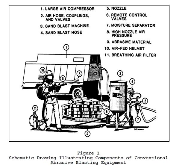
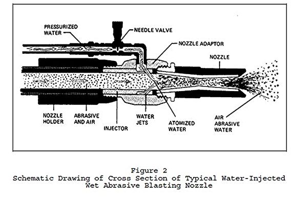
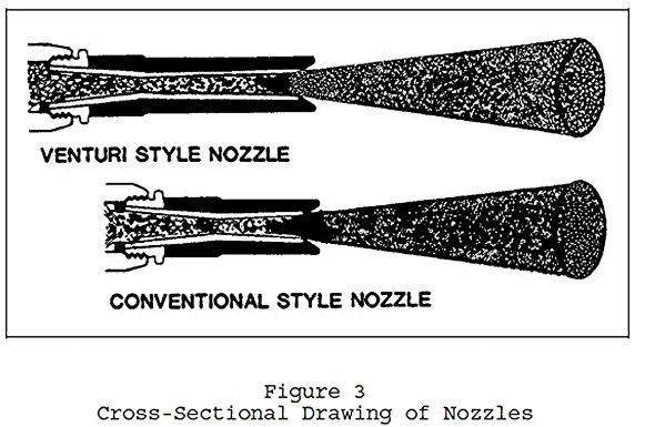
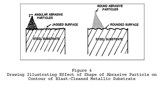
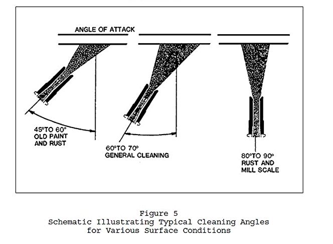
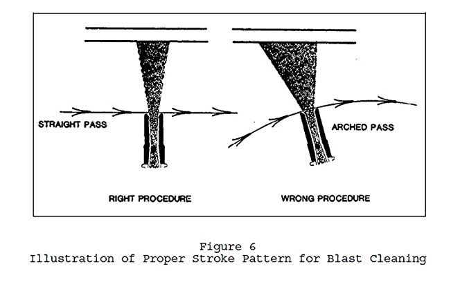
CHAPTER
3
ANALYSIS
OF PAINT FAILURES
1.
DEFINITION. Organic coatings deteriorate and fail with time. Failure
analysis does not concern itself with this type of deterioration. It is defined
as an investigation to determine the cause or causes of premature deterioration
of coatings or coating systems. It is obvious, however, that failure analyses are
often also directed at obtaining additional information than that stated in the
above definition. Thus, the failure analyst may also wish to determine the extent
of the damage, whether all requirements of a specification of a contract or
work order had been met, who might be responsible for the failure and thus be liable
for repairs, or what is the best remedial action to correct the existing
condition.
2. DOCUMENTATION
OF FINDINGS. Measurements, photographs, specimens, and other observations
made at the job-site or later in the laboratory should be firmly documented
with dates, locations, etc., because they may at a later time become legal evidence.
Personnel conducting failure analyses should routinely follow the procedures
necessary for such documentation to prepare for any eventuality.
3. SCOPE OF
FAILURE ANALYSIS. Paint failure analysis can be conducted by anyone with a
basic understanding of coatings. However, they are best conducted by someone
specially trained for the work. This is particularly true if the investigation
becomes part of a dispute, since credibility of the analyst may be a determining
factor in a dispute. In some instances, an analysis need not be extensive, but
care must be taken not to make important conclusions based on superficial
observations. A complete paint failure analysis includes most or all of the following
actions:
a) Review of specification including modifications
b) Review of supplier’s data
c) Review of inspector’s daily reports
d) Thoroughly documented on-site inspection
e) Laboratory analysis of retained and/or field samples
f) Analysis of data
g) Preparation of a report containing findings and conclusions
3.1 REVIEW OF
SPECIFICATION FOR COATING WORK. The specification and the submittals
required in the specification for the coating work should be thoroughly
reviewed and understood. The specification states precisely the work that was to
have been done and the methods and materials that were to be used, so that any
deviations from them should become apparent. The review may also point out discrepancies
or lack of clarity in the document that may have contributed to the failure.
3.2 REVIEW
OF SUPPLIER’S DATA. Supplier data sheets should be reviewed, because they
describe the intended purpose of the coatings used, along with recommended
surface preparation and application practices. They may also include
compositional information that can be checked later by laboratory analysis to determine
if the batch actually used was properly prepared.
3.3 REVIEW
OF INSPECTOR’S DAILY REPORTS. The inspector’s daily reports should be
reviewed, because they provide information about the conditions under which the
work was accomplished and the quality of the surface preparation and coating
application. Any compromises in the conditions required by the specification or
recommended by the supplier may lead to early failure. These reports may also
reveal field changes that were made to the original specification.
3.4 ON-SITE
INSPECTION. Just as the inspector on the job, the person analyzing paint
failures must have access to areas where failures have occurred. This may
require ladders or lift equipment, lighting, or mirrors. The analyst should
also have photographic equipment to document conditions and be skilled in its
use. Scales should be used to show relative size, and permanent markings should
be made on each photographic exposure for positive identification. Dates should
also be placed on the photographs. The analyst should have a standard kit of
field test equipment including one or more thickness gages and calibration standards,
a knife, a hand lens, and containers for samples. Obviously, he should be well
trained in their use and use them systematically, as described elsewhere in
this text. A container of methyl ethyl ketone (MEK) or other strong solvent may
be useful in either determining paint solubility (e.g., verifying the general
paint type or its complete cure) or to strip off a coating to examine the
condition of the underlying surface or the thickness of the underlying
galvanizing or other insoluble coating. Standard forms for manually recording
data or equipment for voice recording are also very useful. A failure analysis checklist
can ensure that no important item is overlooked. Obviously, all items on the list
may not be important at all times, but to inadvertently skip an important one
may be a serious oversight.
3.5 ON-SITE
INSPECTION TECHNIQUES. An overall visual analysis should first be made to
determine the areas where the deterioration is most extensive and where any
apparent deviation from specification may have occurred. This should then be followed
by a closer examination as to the specific types of deterioration that may be
present.
a) Use of a hand lens may provide information not otherwise visually
apparent. All types of failure, including color changes and chalking, should be
described fully. For example, does peeling occur between coats or from the substrate?
Are blisters broken or filled with water? This detailed information may be
necessary for finalizing conclusions as to the type of failure. The terms defined
later in this section should be used to describe failures rather than locally
used terms that may not be clear to other people. Care must be taken not to
come to final conclusions until all the data are analyzed. It is a good
practice to state at the inspection site that the final conclusions on causes
of failure cannot be made until completion of laboratory testing.
b) Dry film thicknesses should be routinely measured and recorded, as any
significant deviations from recommended thicknesses can be a factor contributing
to coating failure. The procedure for measurement of these thicknesses required
in the specification should be followed.
c) Other measurements that may be important are coating adhesion and
hardness, since they may provide important information on application or curing
of the coating. Adhesion can be easily determined with a simple tape test or by
using more sophisticated instrumentation. Hardness can be tested in the field
with a knife or special hardness pencils.
d) It is generally important to verify the identity of the finish
coatings and occasionally the identity of the entire coating system. If wet
samples of the paints used have been retained, they can be submitted for
laboratory analysis for conformance to specification or manufacturer’s data
sheet. If these are not available, a simple solvent rub test may be useful in determining
whether the exterior coatings are thermoplastic, thermosetting, or bituminous.
A cotton-tipped swab stick is dipped in MEK or acetone and rubbed against the
paint surface. A thermosetting coating such as a vinyl which has been deposited
on the surface by simple solvent evaporation will redissolve in the solvent and
be wiped onto the cotton. A bituminous (coal tar or asphalt) coating will also
behave in this manner, but it will impart a characteristic brown stain to the
cotton. Properly cured multiple-component thermosetting coatings such as
epoxies that cure by chemical reaction will not be affected by the solvent.
These solvents can also be used at the job site to remove thermoplastic
coatings to examine the condition of the underlying substrate. The presence of
mill scale may establish the extent of surface cleaning. If rust is found, care
must be taken to determine if it was present before painting or resulted from
underfilm corrosion. Samples of the finish coat can also be removed by sanding
and taken to the laboratory for identification.
e) Once the various types of failure that may be present have been
identified, the extent of each type of deterioration should be estimated.
Standard block methods that help to quantify the extent of coating
deterioration are described in ASTM F 1130, Inspecting the Coating System of a Ship.
Two sets of drawings are used to illustrate failures. One set is used to
identify the portion of the surface on which the paint is deteriorated. The
other set is used to identify the level of deterioration within the
deteriorated areas. For example, a fourth of the surface could exhibit
blistering and within the areas 10 percent of the surface could be blistered.
3.6
LABORATORY TESTING. A more definitive laboratory analysis of deteriorated
paint is generally desired and may become critical if the problem goes into
litigation. Such analyses require several representative paint samples to be collected
at the job site. Peeled and blistered paint is easily sampled, but it may be
necessary to obtain samples from sound paint by scraping or sanding. Each
sample should be placed in a sealed container and properly identified and
dated. Chain of custody procedures (ASTM D 4840, Sampling Chain of Custody Procedures)
should be used if litigation is involved. If samples of wet paint used on the
job are available, they can be tested by standard laboratory tests for
conformance to any SSPC, or specification referenced in the contract
specification. If none of these standards was referenced in the specification,
the paints can be tested for conformance to manufacturer’s listed composition
or properties.
3.6.1
MICROSCOPIC EXAMINATION. Samples of paint collected at the job site should
be examined under a light microscope. An edge examination may reveal the number
of coats and the thickness of each coat. An examination of the surface may
reveal fine cracking or other irregularities. Examination under a scanning electron
microscope (SEM) can reveal much more detailed information about the paint
film. Also, the SEM often has an attachment for energy dispersive x-ray
analysis which can identify the metals and other elements in the pigment
portion of small areas of the coating.
3.6.2 SPOT
TESTS. There are several simple laboratory spot tests that can be run on
samples of deteriorated paint collected at the job site. They generally provide
specific information about the paint binder (ASTM D 5043, Field Identification
of Coatings) or pigment. Special chemicals and training are usually required by
the analyst.
3.6.3
INFRARED SPECTROPHOTOMETRIC ANALYSIS. The most widely used technique in
laboratory analysis of paint failures is the infrared spectrophotometry. The
use of new Fourier transform infrared (FTIR) spectrophotometers permits much more
versatility and precision than earlier instruments. The technique can identify
the resin components of paints from the shapes and locations of their
characteristic spectral peaks. It is highly desirable to separate the resin
from the paint pigment before analysis, because the pigment may cause spectral
interference. This is easy to do with thermoplastic but not thermosetting paints.
Thermoplastic resins can be dissolved in solvents that are transparent in part
or all of the infrared region, filtered to remove the pigment, and the solution
placed in standard liquid cells or cast as films onto sodium chloride or other
plates that are transparent in the infrared region. Thermosetting coatings can
be pressed into potassium bromide pellets or their spectra measured using
diffuse reflectance equipment. Although the pigment is not separated in these
procedures, the spectrum of the pigment can often be separated from that of the
total coating by the FTIR spectrometer. Spectra of field samples are compared against
published standards or authentic samples. It should be remembered that exterior
weathering may cause oxidation that may appear in spectral analyses.
3.6.4 OTHER
SPECIALIZED INSTRUMENTATION. There are other specialized instruments that
can be very helpful in failure analysis. These include emission spectroscopy,
atomic absorption spectroscopy, and x-ray fluorescence instruments that identify
and quantity the metals present in a coating. Their methods of operation are
beyond the scope of this discussion.
3.7 FORMING
CONCLUSIONS AND PREPARING REPORTS. Field and laboratory data should be
analyzed logically and systematically to form conclusions as to the causes of
paint failure. No data should be overlooked, and the conclusions should be
consistent with the data. The report should include conclusions and recommendations
requested by the activity for which the analysis was made. The report is
perhaps the most important part of the failure analysis, because it presents
the findings and conclusions of the investigation. No amount of good field or laboratory
work will be useful unless it is presented well in the report. There must be a
clear, systematic, and logical presentation of the findings, so that the
conclusions are well supported. The report should not contain errors or
otherwise be subject to challenge. Where conclusions are not firm, the extent of
uncertainty should be stated.
4. EXPERT
SYSTEM FOR FAILURE ANALYSIS. An expert system for failure analysis provides
a systematic approach first to make a preliminary identification based on
visual observations and then to verify it with supplementary information. The
initial identification is based upon the answers to a series of questions designed
to distinguish one type of failure from another. Decision trees 1 and 2 are
used for this, one for surface defects and one for film failures. This same
approach can be used in an expert system for a computer. The importance of a
systematic approach cannot be overemphasized. One should be careful not to make
permanent decisions on types and causes of failure until all the evidence is
considered. The first step in the identification of a coating failure is to
determine which decision tree to use. Tree l for cosmetic defects should be
used if only surface damage is present, i.e., if the surface coat has not been
completely penetrated to the underlying coat or structural substrate. Tree 2
for film failures should be used if coating damage has completely extended
through the surface coat. After a preliminary decision of the type of failure
has been made, look at the additional comments in the verification section
below to obtain further support for this selection. If this information does
not support the initial decision, reexamine the evidence or reconsider answers
to the decision tree, until you are satisfied that you received the best
overall answer. Remember, answers are not always easily obtained in failure analysis,
and there may be multiple types and causes of failure. Thus, one may in some
cases have to be content with the most probable cause or causes of coating
failure.
4.1 COSMETIC
DEFECTS. The following paragraphs further describe the cosmetic defects
chosen in the initial decision.
4.1.1
CHALKING. Chalking occurs only on exterior surfaces, since it is caused by the
sun’s ultraviolet rays. The loose chalk will be the same color as the coating,
and, if it is severe, an undercoat may be visible. Chalking should not be confused
with loose dirt which will not be the same color as the finish coat.
4.1.2 MILDEW.
Mildew may resemble dirt but generally grows in discrete colonies rather than
being uniformly distributed. In addition, it can be bleached with household
bleach, but dirt cannot. Also, it can also be identified microscopically by its
thread-like (hyphae) structures and its groups of spherical spores. Mildew is
usually black in color but some microorganisms on coatings may have a green or
red coloration.
4.1.3 DIRT.
Dirt may be tightly or loosely held. It can normally be removed by washing with
detergent solution. However, it may resist washing, if the dirt became embedded
in the wet or soft paint.
4.1.4 UNEVEN
GLOSS. Localized glossy spots may often be detected only if observed from a
particular angle. They occur most frequently from spray application of heavy areas
that do not penetrate into wood or concrete/masonry surface.
4.1.5
BLUSHING. Blushing is a defect from spraying fast-evaporating coatings,
particularly lacquers such as vinyls and chlorinated rubbers, on hot, humid
days. Condensation of moisture on the wet film dulls the finish to cause an opalescence.
4.1.6
BLEEDING. Bleeding occurs when solvent-containing coatings are applied to a
bituminous coating or pavement. The stronger the solvent and the slower its
evaporation, the greater will be the tendency to dissolve the bituminous
material and cause it to bleed to the surface of the finish. New asphalt pavements
or toppings should be allowed to remain 4 weeks before marking with paint to
allow evaporation of volatile materials in the asphalt.
4.1.7 FADING.
Fading of paint pigments occurs greatest in the sunlight. Thus, there will be
less fading of coatings under eaves and other shaded areas. It also occurs more
with synthetic organic pigments than with naturally-occurring mineral pigments (earth
tones).
4.1.8
DISCOLORATION. Discoloration is caused by exposure of unstable pigments or
resins to sunlight. Unstable resins like polymerized linseed oil may yellow.
The only prevention is to use light-stable materials.
4.1.9
PIGMENT OVERLOAD. Pigment overload frequently results in a mottled
appearance or a poor quality film. It can occur when attempting to tint a white
paint to a deep tone. Latex paints are particularly susceptible to this
problem. By specifying colors produced by the supplier, this problem can be avoided.
4.1.10
CHECKING. Early checking may be caused by improper formulation or
application that causes the coating to shrink upon curing. Excessive thickness
or rapid curing may be responsible. Aging will eventually cause checking of
most coatings. It will often occur when existing paints are topcoated with more
rigid finish coats that do not expand or contract as easily.
4.1.11 DRY
SPRAY. Dry spray produces an uneven, pebbly finish with holidays. The
holidays can be verified on a metal substrate with a holiday detector. It
occurs most frequently when applying coatings with fast evaporating solvents on
warm days or when the spray gun is held too far from the surface being painted.
4.1.12
SAGGING. Sags may not permit complete curing of the body of oil-based
coatings and so may be soft below the surface. Reduced film thickness in the
areas where the sagging initiated may be detected using a magnetic thickness
gage on steel surfaces and by using a Tooke gage on other surfaces.
4.1.13
ORANGE PEEL. Orange peel is a defect of spray application. It usually is
widespread, when it occurs, and is easily identified by its resemblance to the
skin of an orange.
4.1.14
WRINKLING. Wrinkling occurs mostly with oil-based paints that are applied
so thickly on hot days that the surface of the film cures rapidly to form a
skin that does not permit oxygen to reach the interior of the film to cure it.
The coating under the ridges is usually soft. Ridges generally occur in parallel
rows.
4.2 FILM
FAILURES. The following paragraphs further describe the film defects chosen
in the initial decision.
4.2.1
CRAWLING. Crawling, sometimes called bug eyeing or fish eyeing, occurs
during coating application, frequently on contaminated surfaces. It can usually
be detected at the time of application. The smooth, oval shapes resembling eyes
are characteristic of crawling.
4.2.2
ALLIGATORING. The characteristic checkered pattern of cracked coating will
identify alligatoring. The coating is quite inflexible and cannot expand and
contract with the substrate. It is a special form of cracking or checking.
4.2.3
INTERCOAT DELAMINATION. Intercoat delamination is simply the peeling of a
stressed coat from an undercoat to which it is poorly bonded. It may occur in a
variety of situations, but occurs frequently when a chemically curing coating
such as an epoxy or a urethane has cured too hard to permit good bonding of a
topcoat. It may also occur when coating a contaminated surface.
4.2.4
INTERCOAT BLISTERING. Intercoat blistering in a storage tank or other
enclosed area is likely due to solvent entrapment. In water tanks or other
areas exposed to water, the trapped solvent will cause water to be pulled into
the blister. If the blisters are large, unbroken, and filled with water, it is sometimes
possible to smell the retained solvent after breaking them. Intercoat
blistering may lead to intercoat delamination.
4.2.5
PINPOINT RUSTING. Pinpoint rusting is frequently caused by applying a thin
coating over a high profile steel surface. A thin coating can be verified using
a magnetic thickness gage. It may also occur when steel is coated with a porous
latex coating system. Pinpoint rusting may initiate corrosion undercutting of
the coating.
4.2.6
CRACKING. Cracking is the splitting of a stressed film in either a
relatively straight or curved line to an undercoat or the structural substrate.
Cracking may occur from rapidly curing coatings such as amine-cured epoxies.
Mudcracking is a more severe condition caused by rapid drying, particularly by
heavily pigmented coatings such as inorganic zincs. It also occurs with latex
coatings applied too thickly on hot days. On wood, too thick or too inflexible
a film (usually a buildup of many layers) can cause cracking perpendicular to
the grain of the wood.
4.2.7
BLISTERING TO SUBSTRATE. The blisters that arise from the substrate may be
broken or unbroken. If broken, they may lead to peeling and be hard to
identify. Blistering to wood or concrete/masonry substrates may be caused by
moisture in the substrate.
4.2.8
PEELING. Peeling is the disbanding of stressed coatings from the substrate
in sheets. It is generally preceded by cracking or blistering.
4.2.9
FLAKING (SCALING). Flaking or scaling is similar to peeling, except the
coating is lost in smaller pieces. Flaking of aged alkyd coatings occurs
commonly on wood.
4.3 EXAMPLES
OF USING DECISION TREES. The decision trees 1 and 2 (Figures 1 and 25 can
best be understood by using examples.
4.3.1
EXAMPLE OF SURFACE DEFECT. This example is a surface defect that does not
penetrate the finish coat so that use of decision tree 1 is required. We start
with Question 1, “Does detergent washing remove the defect?” In our example,
the answer is “Yes,” so we proceed to Question 2, “Does wiping with a dry felt
cloth remove defect?” This time the answer is “No,” so we proceed to Question
3, “Does defect disappear when treated with household bleach?” In our example,
the answer is “Yes,” so we have tentatively identified the defect as “Answer 2”
mildew.
4.3.2
EXAMPLE OF A FILM DEFECT. This example is a defect that penetrates the
finish coat so that use of decision tree 2 is required. We start with Question
10, “Do oval voids that originate at time of coating application expose an
undercoat or the structural substrate?” In our example, the answer is “No,” so
we proceed to Question 11, “Does the failure expose only an undercoat?” This
time the answer is “Yes,” so we proceed to Question 12, “Which best describes
the failure?” In our example, the answer is “Peeling topcoat to expose
undercoat,” so we have tentatively identified the defect as “Answer 17”
intercoat delamination.
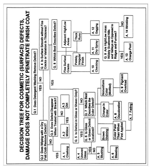
Figure 1
Decision Tree 1: Support for Analysis of Coating Failures
That
Do Not Penetrate the Finish Coat
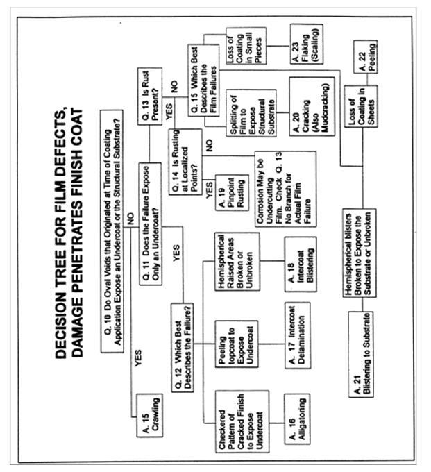
Figure 2
Decision Tree 2: Support for Analysis of Coating Defects
That
Penetrate the Finish Coat
5.
PROGRAMMING MAINTENANCE PAINTING.
5.1
DEFINITIONS OF PROGRAMMED PAINTING AND MAINTENANCE
PAINTING.
Paint programming is a systematic planning process for establishing when
painting is required, what painting should be done, by whom, at what times, and
in what manner. Maintenance painting is a vital adjunct to programmed painting.
It is defined as a field procedure for maintaining existing coatings in an
acceptable condition.
5.2
COMPONENTS OF PROGRAMMED PAINTING. There are three basic components of
successful paint-programming plans: plans for initial design of the facility,
plans for monitoring conditions of structures and coating systems, and plans
for maintenance painting. Each plan must be prepared properly and completely
for the total program to be successful. Programmed painting can best be
implemented as a computer program. This program will contain the initial design
data, data on the conditions of the structures and their coating systems
obtained from an annual inspection report, and recommended maintenance painting
schedules and procedures. The latter should include cost estimates for each
item of work so that funding can be requested well in advance of the time it
will be spent. Cost estimating programs for construction work are available in
the Construction Criteria Base (CCB) (National Institute of Building Sciences, Washington,
DC) and proprietary sources.
5.2.1
INITIAL DESIGN. The design of both new structures and their coating systems
is critical to achieving maximum life of each.
5.2.1.1
STRUCTURAL DESIGN. Structures should be designed so that they are easy to
coat initially and to maintain in an acceptable condition. Common structural
design defects include:
a) Contact of Dissimilar Metals. The more active metal will rapidly be
consumed by galvanic corrosion to protect the less active metal. This includes
contact of steel and stainless steel.
b) Water Traps. Structural components that collect rainwater corrode more
rapidly. These components should either be turned upside down or have weep
holes of sufficient size and correct placement drilled in them. Weep holes
should be as large
as possible and placed at the bottom of the structure.
c) Configurations That Permit Vapors or Liquids to Impinge on Structural
Components. Structures such as steam lines.
d) Configurations Restricting Access. Structures that restrict access for
painting receive poor quality maintenance.
e) Designs Creating Crevices. Crevices are difficult to coat, and the
oxygen deficiencies in them produce a type of galvanic corrosion.
f) Other Difficult to Paint Surfaces. Sharp edges and welds should be
ground, pits should be filled, and corners should be avoided.
5.2.1.2
DESIGN OF COATING SYSTEM. The original coating system must be designed to
be compatible with both the environment in which it is to be located and the
substrate to which it is to be applied. As far as possible, it is desirable to
specify coating systems that are easy to apply and maintain. It is always
preferable to do the surface preparation and the paint application in the
controlled environment of a shop as compared to the field. If this is not possible,
this work should be accomplished at the work site before rather than after
erection.
5.2.2 PLAN
FOR MONITORING CONDITIONS OF STRUCTURES AND THEIR
PROTECTIVE
COATINGS. Annually, each coated structure at each activity should be inspected
for deterioration of both the substrates and their coatings. Both the types and
the extent of deterioration should be noted, and the generic type of the finish
coat should be determined if it not already known. An estimate should also be
made as to when structural and coating repairs should be made to prevent more
serious damage. Other structures at the activity that require the same type of maintenance
should also be noted, since it would be more economical to include as many
structures as appropriate in a single contract. An example of an inspection
form which has been successfully used for routine inspections and could be
modified to meet an installation’s needs is shown in Figure 3.
5.2.2.1
DETERMINING THE TYPE OF COATING FAILURE. The type of coating failure can be
determined by following the procedure described.
5.2.2.2
DETERMINING THE EXTENT OF COATING FAILURE. In maintenance painting, it is
necessary to determine the extent of coating failure to permit realistic
bidding for the repair work. To do this, both the severity of the deterioration
and its distribution must be defined. The level of severity will indicate
whether only the finish coat or other coats are involved in the deterioration
and how it can best be repaired. If the distribution is limited, spot repairing
is likely to be practical; if it is extensive, it is probably best to remove
all the coating and repaint. Standard block diagrams for estimating coating deterioration
on ships for “Overall Extent” and “Extent Within Affected Areas” are generally
also appropriate for shore structures. They are described in ASTM F 1130.
First, draw an imaginary line enclosing all deterioration and select the standard
“Overall Extent” diagram that best matches the imaginary area. Then, select the
standard “Extent Within Affected Area” diagram that best matches the areas
within the imaginary line. The number and letter of the selected diagrams
establish the extent of deterioration. Whatever system is used to determine the
extent of deterioration, it should utilize a standard format so that
evaluations of different structures can be compared and priorities can be
established. It is also important in maintenance painting to determine
precisely the amount of loose and peeling paint to establish the amount of work
to be done. This will eliminate any controversy over a “site variation,” i.e.,
the contractor claiming that there was much more work necessary than described in
the specification. It is a standard practice to define “loose and peeling
paint” as that paint that is easily removed with a dull putty knife.
5.2.2.3
DETERMINING THE GENERIC TYPE OF THE FINISH COAT. Once a painting program is
set up, the identifications of paints being applied will automatically be entered
into the database. If the generic type of the finish coat is not known, it can
be determined by infrared spectrophotometric analysis. The general compatibility
of a coating can be determined by the solvent rub test.
5.2.3 TYPES
OF MAINTENANCE PAINTING. In planning maintenance painting, it is first
necessary to determine the general scope of the work. There are four different
approaches to maintaining an existing coating in an acceptable condition:
a) Cleaning only to restore to an acceptable condition. This may be accomplished
by pressure washing or steam cleaning.
b) Spot repair (priming and topcoating) of areas with localized damage but
otherwise sound paint. This should be done before the damage becomes more
extensive.
c) Localized spot repair plus complete refinishing with topcoat only.
This should be done when localized repair only would produce an unacceptable
patchy finish.
d) Complete removal of existing paint and total repainting. This should
be done when the damage is so extensive that types “b” or “c” are impractical
or uneconomical.
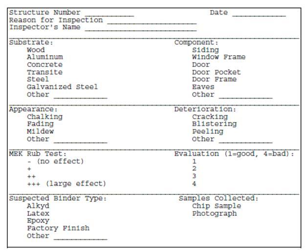
Figure 3
Coating Condition and Identification Form
Repair of
exterior coatings may not be warranted with the first appearance of weathering,
but deterioration should not proceed to the point that damage occurs to the
substrate, or more costly surface preparation or application techniques become necessary.
If lead-containing paint is present, the costs for paint repair or removal will
be much more expensive. If the paint can be maintained in place, a great deal
of savings will result. New restrictions on abrasive blasting and other surface
preparation techniques may also significantly increase total costs. Thus,
scheduling of repairs should be made to avoid such costly operations.
5.2.4 PLAN
FOR MAINTENANCE PAINTING. The plan for maintenance painting includes
selection of the surface preparation, application, and inspection methods and
the materials to be used.
5.2.4.1
SELECTING MATERIALS FOR MAINTENANCE PAINTING. For localized repairs to an
otherwise sound coating system (types “b” and “c”), it is wise to repair a
damaged coating system with the same coating previously used or one of the same
generic type or curing mechanism to avoid incompatibility. If in doubt as to
the compatibility of a paint to be applied to an existing finish, apply a small
patch to it and inspect it after 2 to 3 days for any bleeding, disbanding, or
other sign of incompatibility. For total recoating (type “d”), select the coating
as described for new work.
5.2.4.2
SURFACE PREPARATION FOR MAINTENANCE PAINTING. For making localized repairs,
it is best to use the surface preparation methods for different substrates described.
It may be more practical or necessary, however, to use hand or power tools
rather than abrasive blasting where the amount of work to be done is small, or
where abrasive blasting would contaminate an area. Loose and peeling coating
should be removed, and the adjacent intact coating should be sanded to produce
a feathered edge and roughened paint surface extending 2 inches beyond the repair
area. The feathered edge will produce a smoother transition between the old and
new paint and roughening the adjacent intact paint will permit good adhesion of
the new primer. Feather edging of steel may be accomplished by blasting with a
fine abrasive (e.g., 60 mesh grit or finer) with the nozzle held at a low angle
about 3 or 4 feet from the surface.
However, even fine
abrasive may damage adjacent coating. Thus, it is best to determine if there
are any adverse effects with a surface preparation procedure before proceeding
will it.
5.2.4.3
APPLICATION FOR MAINTENANCE PAINTING. Spot application of paint in maintenance
painting is usually done by brush or spray, as the painter determines to be
most efficient. Brushing of the primer is usually preferred where the surface
is rough or otherwise difficult to paint. Patches should be extended 2 inches
beyond the areas of damaged coatings where the adjacent intact paint has been
previously roughened.
5.2.4.4
INSPECTION OF MAINTENANCE PAINTING. Inspection of maintenance painting
usually consists of visual inspection for workmanship, dry film thickness, and
adhesion. Fuel tanks and lines, waterfront structures, and other critical
structures should also be tested for holidays Imperfections in the coating).
5.2.5
SCHEDULING THE WORK. By planning work well in advance, it is possible to
schedule it at a time when minimum inclement weather is expected. It may also
be possible to schedule it when there will be less interference with other
trades doing construction work or personnel utilizing the structures.
CHAPTER
4
INSPECTION
OF PAINTING OPERATIONS
1.
INSPECTION OF PAINTING OPERATIONS
1.1 SCOPE.
This section describes the duties of an inspector, general inspection
procedures, and specific inspection methods used in inspecting painting
operations. Depending upon the job and the contract requirements, quality control
inspectors may be contractor-supplied (that is, contractor quality control -
CQC) or Owner personnel. In either case, the contracting officer
NOTE:
Construction contract terminology is variable. In this publication the term
“contracting officer” refers to the Owner’s representative for the project who
has contractual authority over execution of the construction contract.
is responsible
for ensuring the quality of the job. The intent of this section is to describe
proper inspection procedures so that Owner personnel will know either how to
inspect a painting operation or to ensure that someone else has done it
correctly.
1.2
IMPORTANCE OF INSPECTION. The success of a painting job depends upon the
specification requirements being met for surface preparation, application and
materials. Most coating failures are the result of contract requirements not
being met. Inspection procedures are designed to detect situations when the requirements
of the contract are not being met. Thus, inspection is a key factor in
obtaining the performance and durability built into the specification.
1.3
CONTRACTOR QUALITY CONTROL INSPECTION. In Owner painting, quality control
inspection is often provided by the contractor. For large jobs, a contractor
usually hires an inspector. For smaller jobs (less than $200,000), a
contractor's superintendent may carry out the quality control inspection. If deemed
necessary because of the size or difficulty of a job, or because of the crucial
function of a structure, the contract specification can require the contractor
to hire a certified inspector (e.g., NACE has a certification program). In this
way, the contractor's inspector may be more independent of the contractor and
may have better inspection skills. Although this requirement may increase
inspection costs, the increased cost of proper inspection as opposed to none or
poor inspection has been found by the private sector to be cost effective.
Quality control inspectors should report deviances from the contract specification
in writing to the contracting officer. Appropriate Owner action in response to
these reports is essential in obtaining the quality of the job built into the
specification.
1.4 DUTIES
OF AN INSPECTOR. The duties of an inspector include understanding the
contract specification requirements, making sure that the specification
requirements are met by the contractor, and keeping good records. Record
keeping is a very important part of inspection. It should occur during all
phases of the job. Records form an important part of the permanent record on
each building, and provide key information in the case of contract disputes.
1.4.1 RECORD
KEEPING. Inspectors should keep records in a bound book (logbook). Each
page should be initialed by the inspector and dated. The record book should
contain:
·
Written records of verbal agreements made between the contracting
officer or the inspector and the contractor.
·
Daily descriptions of the type of equipment and number of workers
on the job site.
·
Descriptions of the coating materials that are on site.
·
Records of the rate of work progression. e) Measurements of
ambient conditions.
·
Results and observations of the surface preparation inspection.
·
Measurements and observations of coating application, including
time between surface preparation and coating application, and times between
coats.
·
Results of the final and warranty acceptance inspections.
It is
especially important that agreements between the contracting officer (or
designee) and the contractor that modify the contract specification be in
writing and be signed to minimize future disputes.
1.5
INSPECTION EQUIPMENT. A description of equipment used in typical
inspections is summarized in Table 1. Instructions on its use are provided in
the equipment manufacturer's literature. Some of the equipment is readily available
from local hardware or variety stores but some is specialized equipment for
painting operations. Suppliers of specialized equipment are listed in:
·
ASTM, 1916 Race Street, Philadelphia, PA 19103.
·
NACE, P.O. Box 218340, Houston, TX 77218.
·
SSPC, 516 Henry Street, Suit 301, Pittsburgh, PA 15213-3738.
·
Paul N. Gardner Company, Inc., Gardner Building, P.O. Box 10688,
Pompano Beach, FL 33060-6688.
·
KTA-TATOR, Inc., 115 Technology Drive, Pittsburgh, PA 15275.
·
ZORELCO, P.O. Box 25500, Cleveland, OH 44125.
·
Pacific Scientific, 2431 Linden Lane, Silver Spring, MD 20910.
·
S. G. Pinney & Associates, 2500 S.E. Midport Road, P.O. Box
9220, Port St. Luice, FL 34952.
1.6
INSPECTION STEPS. The inspector's tasks can be divided into eight general
steps, which are summarized in Table 2 and discussed in more detail below.
Special equipment required in each of these steps is also listed in the table.
A form that may be useful in reviewing the contract is provided in Figure 1, and
one for organizing inspection data is provided in Figure 2.
1.6.1 REVIEW
SPECIFICATION AND CORRECT DEFICIENCIES, If Any. The first part of any
inspector's job is to read and understand the contract specification. If
deficiencies are found, resolution of the deficiencies between the contracting
officer and the contractor is needed prior to start of work. Any changes in the
contract specification must be documented in writing and signed by the two
parties or their representatives. Copies of these agreements should be kept in
the inspector's records. In addition to reviewing the specification, the
inspector must also review the contract submittal. The form shown in Figure 1
may help an inspector to identify key specification requirements and essential
information from the submittals, and to prepare for the preconstruction
conference. Note that at this time, all the information needed to complete the
form may not be available. However, the information should be available before
the start of the job.
1.6.2 VISIT
JOB SITE. It is important for the contractor to visit the job site with an
inspector prior to the preconstruction conference so that the scope of the job and
any constraints are understood. Potential problems that are found, such as difficulty
with access to the job site, can then be resolved at the preconstruction
conference. Such visits have been shown to be effective in reducing problems
during the job.
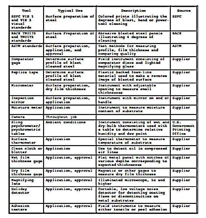
Table 1
Equipment for inspecting painting operations
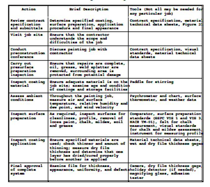
Table 2
Inspection steps

Figure 1
Sample inspector’s contract summary form
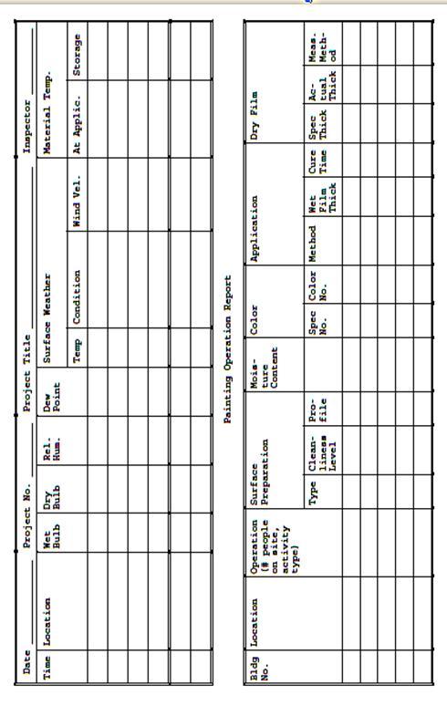
Figure 2
Sample daily project reports for painting inspectors
1.6.3
CONDUCT PRE-CONSTRUCTION CONFERENCE. At the beginning of each new contract
or work order before the start of any surface preparation or coating
application, a meeting should be held with the contractor, contracting officer,
inspector, and
other key
people. Figure 1 may be helpful in this discussion. During this conference,
agreement should be reached on details of the specification and the procedures
and expectations of the inspector. For example, the number and locations for
inspecting surface preparation and coating thickness should be determined. Scheduling,
job sequencing, job stops for inspection, and other job-related issues should
be discussed. Differences between contractor and contracting officer should be
resolved at this time to avoid future misunderstandings and job delays. Agreements
that result in a change of the contract should be made in writing, signed and
included in the record book.
1.6.4
INSPECT JOB SITE AFTER PRE-SURFACE PREPARATION. Prior to surface
preparation or coating application, it is necessary to be certain that requirements
in the specification relating to readying a surface or area for painting are
carried out. These may include protecting adjoining surfaces, removing weld splatter,
ensuring that surfaces are free of oil and grease, grinding sharp metal edges,
protecting plants and other shrubbery, replacing rotted wood, caulking joints,
and the like.
1.6.5
INSPECT COATING MATERIALS. Coating materials must be inspected at the job
site to identify deficiencies that could result in failure of the paint film.
The following checklist can be used:
·
Read labels on the coatings to verify that the coatings are the
ones specified or approved.
·
Take one representative 1-quart sample in accordance with the
specification. Retain the sample for a period of 1 year from the date of final
approval of the contract work in case of coating film failures or contract
disputes.
·
Ensure that coating materials are in sealed, unbroken containers
that plainly show that the date of manufacture is within 1 year. The label
should display the manufacturer's name, specification number/or designated
name, batch number, and FED-STD-595 color.
·
Inspect the paint after stirring for homogeneity, weight,
viscosity, color, and smell. If deficiencies are suspected from these tests,
the paint should be sent to a laboratory for testing.
·
Count the cans of paint on the job site to determine that a
sufficient quantity is available to complete the job as specified. For
multi-component paints, confirm that the proper ratio of materials for each
specific coating is present. To estimate the paint required for a job, use the
nomograph shown in Figure 3.
·
Ensure that the paint is stored on site in an approved building
or area.
·
Record number of cans and paint condition in record book.
1.6.6
MEASURE AMBIENT CONDITIONS. Most coating systems will not dry or cure
properly under extremes of temperature or humidity, nor will they adhere well
if applied over damp surfaces. For example, specifications often require that
the substrate surface temperature be 5 degrees F above the dew point and
rising. For these reasons painting contracts have requirements for air and
surface temperature, dew point, and, perhaps, additional environmental
conditions. The paint manufacturer's technical data sheet will also have limits
for acceptable environmental conditions. (If the limits are in conflict,
agreement on the limits should be reached during the preconstruction
conference.) Because temperature and dew point may vary considerably within a
small area, temperature and dew point should be measured in the immediate
vicinity of the work being done. Surfaces being painted may be colder than the atmospheric
temperature and their temperatures should be measured in addition to
atmospheric temperatures. Dew point at the surface being painted may also be different
from that in the air away from the surface. Thus, dew point should be measured
near the surface. Ambient condition measurements should be made about every 4
hours. These times should include before start of job, after breaks, and after
sudden changes in environmental conditions. Sudden changes in environmental
conditions should also be recorded in the logbook. In addition, do not paint in
rain, snow, fog, or mist, or when the surface is covered with frost.
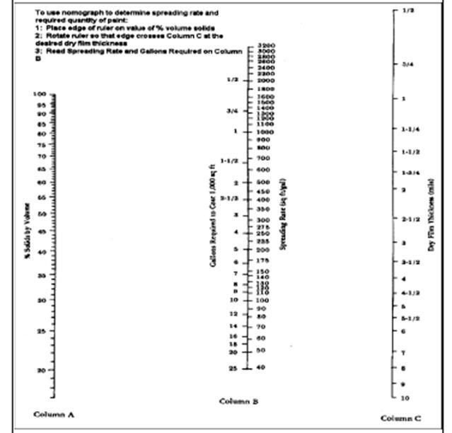
Figure 3
Nomograph for
estimating quantities of paint required for a job
1.6.6.1
RELATIVE HUMIDITY AND DEW POINT. These conditions are measured using a
psychrometer. Most psychrometers consist of a wet bulb thermometer, a dry bulb
thermometer, and a standard psychometric table. Using the table, the relative
humidity is obtained from the two temperature readings.
1.6.6.2
SURFACE TEMPERATURE. Surface temperature is measured using a special
thermometer in which the temperature sensing element is designed to come into
intimate contact with the surface and to be shielded from the surrounding air.
The surface temperature of the coldest and warmest surfaces should be within the
limits of the specification. The location, temperature and time of the
measurement should be recorded in the record book.
1.6.7
INSPECT SURFACE PREPARATION. Surface preparation inspection procedures
include inspecting equipment, and associated materials (e.g., blasting medium
and chemicals), as well as the cleaned surface itself. Proper surface
preparation, as described in the specification, must be completed to obtain a durable
coating film.. Many of the surface preparation requirements involve visual
inspection of the surface, and some are subjective. For example, the
specification may require removal of loose paint (for example, paint that can be
removed by a dull putty knife), removal of surface chalk to some specified
level and feathering of edges on the remaining paint film. To help avoid
conflicts between the contractor and the inspector, it may be useful to have
the contractor prepare a test surface about 4 by 4 feet that can then be used
as a standard for surface preparation. Photographs of the test surface could be
part of the inspection record. For steel, the test surface should be protected
by a clear coating. When blast cleaning is part of the surface preparation, it
should be performed in a manner so that no damage is done to partially or
entirely completed portions of the work, adjacent surfaces, or equipment.
Usually blast cleaning should progress from the top towards the bottom of a
structure, should be carried on downwind from any recently painted structures,
and should not scatter abrasive on or into surrounding buildings or equipment. All
dust from blasting operations must be removed by brushing, blowing, or vacuuming
before painting.
1.6.7.1
ABRASIVE-BLASTING SURFACE PREPARATION EQUIPMENT AND SUPPLIES
1.6.7.1.1
AIR CLEANLINESS. Routinely (at least two times a day or every 4 hours)
inspect air supply lines for both blast cleaning or paint spray application to ensure
that the air supply is clean and dry. A blotter test as described in ASTM D
4285 can be used to determine whether the air supply is free of oil and moisture.
In this test, a clean white blotter is held downstream about 19 inches from the
nozzle for 2 minutes. It should remain clean and dry.
1.6.7.1.2
ABRASIVE. Each batch or shipment of abrasive should be checked for oil
contamination and, if required, soluble salts. Either can contaminate a cleaned
surface and reduce the service life of the coating. A commonly used test to
check for oil contamination is to take a small random sample of the abrasive,
place it together with clean water in a small bottle or vial, shake the bottle
for a minute and examine the surface of the water. There should be no sheen of
oil on the surface of the water. Soluble ionic contaminants can be detected
using the electrical conductivity test described in ASTM D 4940. In addition,
the abrasive should feel dry to the touch when it is placed in the abrasive
blasting machine. Recycled abrasives break down after several cycles, and the
number of cycles depend upon the type of the abrasive. The abrasive should be
replaced when it no longer meets the requirements of the specification.
1.6.7.1.3
BLAST HOSES AND NOZZLES. Blast hoses should be in good condition and kept
as short as possible. The nozzle pressure and diameter of the nozzle orifice
both affect the cleaning rate. A nozzle orifice gage is used to determine the orifice
size. Air pressure at the nozzle is measured using a hypodermic needle air
pressure gage and should be from 90 to 100 psi for optimum efficiency. Usually
these parameters are measured at the start of a job and when production rates
are decreasing. An increase of nozzle size of more than 1/8-inch causes loss of
cleaning efficiency because of the increased pressure drop. Increased nozzle
size also causes increased use of abrasive. Profile should be inspected when
major changes in cleaning efficiency are noted.
1.6.7.1.4
SAFETY. Special safety precautions are required during abrasive blasting.
Refer to Section 13 for more information. These precautions include use of
external couplings on blast hoses and dead man controls, and electrical
grounding of equipment.
1.6.7.2
WATER BLASTING. Since contaminants, such as salts and oils, in the blasting
water will be left behind on the blast cleaned surface and may adversely affect
the adhesion of the coating to be applied, water should be essentially free of contaminants.
If cleaning agents are added to the water used for blasting and cleaning, the
surfaces must be thoroughly rinsed with clear water. An exception is the use of
flash-rusting control agents when cleaning steel. These agents should only be used
in accordance with the contract specification and the coating manufacturer's
recommendations. As for abrasive blasting, hoses should be in good condition
and kept as short as possible. Special safety precautions, similar to those
used in abrasive-blast cleaning, also need to be taken. In addition, consideration
should be given to the slipperiness of wet
surfaces.
1.6.7.3
FREQUENCY OF INSPECTING CLEANED SURFACES. The objective of the inspection
is to ensure that the entire surface was prepared in accordance with the
specification. The inspection report should provide a representative
description of the cleaned surface. The specific number and location of places at
which surfaces should be inspected must be in accordance with the contract
specification. If not detailed in the specification, SSPC PA 2 can be used as a
guide. Additional inspection sites that should be considered include those
where the existing paint was failing, in hard-to-reach areas where surface
preparation is difficult, and where major changes in equipment were made.
1.6.7.4
INSPECTING PREPARED STEEL SURFACES.
1.6.7.4.1
CLEANLINESS. If a small representative sample of surface was not prepared
to use as the standard for surface preparation, the degree of blast or tool
cleaning should be compared to the description given in the SSPC or NACE specification
referred to in the contract specification. The appearance should correspond
with the specified pictorial standards of SSPC VIS 1, SSPC VIS 3, or a NACE
panel. After blasting, blast-cleaned surfaces must be cleaned (e.g., vacuum,
air blast, or brushing) to remove traces of blast products from the surface or
pitted areas. One of two tests for cleanliness can be used. In one, a white
glove or other clean cloth is rubbed over the surface and examined for soiling
or debris, and in the other, a piece of clear adhesive tape is applied to the
surface, removed and the adhesive side examined for debris.
1.6.7.4.2
PROFILE. Profile is measured using one of three pieces of equipment:
comparator, depth micrometer, or replica tape. It should be noted that the
three techniques may give slightly different results. Complete descriptions of
standard methods for each of these techniques are described in ASTM D 4417,
Field Measurement of Surface Profile of Blast Cleaned Steel.
1.6.7.5
INSPECTING CONCRETE, MASONRY, WOOD, PLASTER, WALLBOARD, OLD PAINT. On these
surfaces, specifications may have requirements for measurements of moisture
content and residual chalk, as well as visual condition. The specification
should state how moisture is to be measured, since the different methods provide
different types of data. Moisture content can be measured either using a
plastic sheet test (ASTM D 4263) or an electric moisture meter. In the plastic
sheet test, a piece of plastic film is taped (all edges) to the surface. After
24 hours, the film is removed and the underside is examined for the presence of
condensed water. Prior to application of most coatings, the sheet should be
free of condensed water. This is because accumulation of water at the
concrete/primer interface will usually lead to delamination of the primer. To
use a moisture meter on hard surfaces, small holes must drilled for the electrodes.
These holes should be repaired after the measurements are completed. The
contract should state a moisture requirement. Residual chalk is usually
measured using a piece of cloth of contrasting color, in accordance with ASTM D
4214. Other procedures are also described in ASTM D 4214. In the cloth method,
a piece of cloth is wrapped around the index finger, placed against the surface
and then rotated 180 degrees. The spot of chalk on the fabric is compared with
a photographic reference standard. Chalk readings of 8 or more indicate adequate
chalk removal providing reasonable assurance that the new coating should not
fail because of application to a chalky surface.
1.6.8
INSPECT COATING APPLICATION. Proper application is another essential factor
in determining paint performance, and the requirements of the specification
must be followed. General guidance on paint application is presented in Section
7 and SSPC PA-1. Inspectors should assess ambient conditions, application equipment,
ventilation, mixing, film thickness, and drying and curing conditions to ensure
that they are within the limits of the specification and the technical data
sheets for the paints. It is especially important that the paints be applied
and cure within the temperature and relative humidity limits of the specification,
since these conditions affect film formation. A properly dried and cured film
is essential for satisfactory paint performance, and deviations from these
limits may prevent proper film formation. For two-component systems, the
inspector should ensure that the materials were mixed together and in the
proper ratio. For all materials, thinning should only be allowed in accordance
with the manufacturer's data sheet.
1.6.8.1
APPLICATION EQUIPMENT. Equipment to apply the coating must be in acceptable
working condition. When spraying, the spray pattern should be oval and uniform,
the gun should be held at the proper angle and distance from the surface, and
each spray pass should overlap the previous one by 50 percent. Proper techniques
should also be used for brushing, rolling, or other application procedures.
Refer to Section 6.
1.6.8.2
VENTILATION. The ventilation of tanks and other enclosed areas where paint
is to be applied and cured must meet the requirements of OSHA's Confined Space
Regulation, and the contractor's safety plan required by contract
specification. Good ventilation is also necessary for proper coating cure.
1.6.8.3
MIXING/THINNING. Paints must be properly mixed. Paint solids often settle
out during storage and must be completely blended into the paint vehicle, resulting
in homogeneous mixture. For multi-component paints, the inspector should ensure
that all components have been mixed in the proper proportion, that the mixing
is thorough and that the resulting paint is uniform in appearance. Required
induction times must also be met to obtain satisfactory application and film
properties. Although the paint manufacturer prepares paint to produce a
consistency for brushing, rolling, or spraying, sometimes additional thinning
is permitted in the specification. Thinning of the paint must follow
manufacturer's instructions for both type and amount of solvent. A thinned
paint will cover more surface area but the dry film thickness will be less and
may not
meet the
requirements of the specification.
1.6.8.4 FILM
THICKNESS. Contract specifications may require a minimum and/or a maximum
dry film thickness for each coating application. Wet film thickness
measurements made at the time of paint application are used to estimate dry
film thickness so that appropriate adjustments in the application procedure can
be made
to meet the
specification. Wet film thicknesses are not used in meeting contract
requirements because of the many factors (solvent evaporation, wetting
energies) that affect the measurement. Procedures for making wet film thickness
are described in ASTM D 4414, Wet Film Thickness by Notch Gages. The dry film
thickness is estimated from the wet film thickness according to:
·
Dry Film Thickness = Wet Film Thickness x Percent Volume Solids
The percent
volume solids is available from the coating manufacturer's data and should be
part of the inspector's records. Dry film measurements are made after the
coating has hardened. For steel surfaces, thickness measurements can be made according
to SSPC PA 2 or ASTM D 1186 or ASTM D 1400, Nondestructive Measurement of Dry
Film Thickness of Nonconductive Coatings Applied to a Nonferrous Metal Base.
(There are some differences in calibration procedures between SSPC PA 2 and the
ASTM standards. If the contract specification does not specify the exact
procedures to be used, the procedures should be agreed upon, and the agreement
documented, during the preconstruction conference.) ASTM D 4128, Identification
of Organic Compounds in Water by Combined Gas Chromatography and Electron
Impact Mass Spectrometry describes a destructive procedure for measuring coating
thickness on non-metallic substrates using a Tooke gage. If the contract
specification requires minimum film thicknesses for each layer, the
measurements must be made after each layer has cured, taking care not to
depress soft coatings during measurements.
1.6.8.5
DRYING. The inspector should ensure that a previous coat has dried or cured
as required by the contract specification before another coat is applied. For
most thermosetting coatings, manufacturers specify a maximum, as well as a minimum,
curing time before application of the next coat. In some situations, a coating
manufacturer may require use of a methyl ethyl ketone (MEK) rub test to assess
curing prior to application of another layer. The inspector's record should
provide information so that the dry/cure time for each layer can be determined.
1.6.9 FINAL
APPROVAL PROCEDURES. The final approval inspection is very important since
it determines whether the contract requirements have been met, and whether
identified deficiencies have been corrected. Since most coatings function as a
barrier and since the protection of a surface is usually directly related to
coating thickness and continuity, inspection of coating thickness and film
continuity are essential. The following checklist can be used to inspect the
final job:
1.6.9.1
EXAMINE, as required by the specification, the cured coating system for
visual defects, such as runs, sags, blistering, orange peel, spray
contaminants, mechanical damage, color and gloss uniformity, and incomplete
coverage. Note any areas of rusting, or other evidence of premature failure of
the coating system.
1.6.9.2 IF
DEFECTS ARE OBSERVED, bring them to the attention of the contractor for
correction. If resolution of the corrective action cannot be reached with the
contractor, bring the matter to the attention of the contracting officer. Dated
photographs of the defects could become part of the inspector's records, if
deemed appropriate.
1.6.9.3
MEASURE AND RECORD the total dry film thickness using appropriate gages. Wh
en the Tooke gage is used, the coating must later be repaired.
1.6.9.4
MEASURE ADHESION as required in the contract specification. Adhesion
measurements vary from those made with a knife (ASTM D 3359, Measuring Adhesion
by Tape) to those that determine the amount of force needed to remove a dolly
(ASTM D 4541, Pull-Off Strength of Coatings Using Portable Adhesion Testers)
that has been cemented to the surface.
1.6.9.5
EXAMINE THE COATINGS on steel structures for pinholes using a holiday
detector as described in NACE RP0188, if required in the contract
specification.
1.6.9.6
RECORD THE RESULTS of observations in the record book. Document photographs
taken and retain in the record book.
1.6.10 YEAR
WARRANTY INSPECTION. The warranty inspection includes a visual inspection
of the film, and may involve a chalk, film thickness, and adhesion
measurements. Since the film was found to be essentially free of defects upon
completion of the job, a goal of the inspection is to identify contractually unacceptable
defects that have formed during the course of the year. Resolution of film
deficiencies should follow the same steps as for the final inspection.
Deficiencies should be recorded in the logbook. Documented photographs (date,
location, and photographer) should be included if deemed necessary to resolve
contract disputes.
2. FIELD
INSPECTION INSTRUMENTS
2.1
INTRODUCTION. This section describes field instruments commonly used in
inspection of field painting. For equipment descriptions having no referenced
standards, no standards are available. Typical suppliers include:
·
Paul N. Gardner Company, Inc., Gardner Building, P.O. Box 10688,
Pompano Beach, FL 33060-6688.
·
KTA-TATOR, Inc., 115 Technology Drive, Pittsburgh, PA 15275.
·
ZORELCO, P.O. Box 25500, Cleveland, OH 44125.
·
Pacific Scientific, 2431 Linden Lane, Silver Spring, MD 20910.
·
S. G. Pinney & Associates, 2500 S.E. Midport Road, P.O. Box
9220, Port St. Luice, FL 34952.
2.2
ILLUMINATED MICROSCOPE. A pocket-sized illuminated microscope is frequently
used to detect mill scale, other surface contamination, pinholes, fine
blisters, and other microscopic conditions during painting operations. These
microscopes are available with magnifications of 5 and higher.
2.3
INSTRUMENTS FOR USE WITH ABRASIVE BLASTING. A few instruments are available
for testing the operational readiness of equipment for abrasive blasting of
metals for painting.
2.3.1 GAGE
FOR DETERMINING NOZZLE PRESSURE. A pocket-sized pressure gage with a
hypodermic needle is used to determine the blasting pressure at the nozzle. The
needle is inserted in the blasting hose just before the nozzle in the direction
of the flow. Instant readings can be made up to 160 pounds per square inch
(gage) (psig).
2.3.2 WEDGE
FOR DETERMINING DIAMETER OF NOZZLE ORIFICE. A hand-held calibrated wedge is
inserted in the direction of flow into the nozzle orifice to determine its size
(inches) and airflow (cfm at 100 psig). The orifice measuring range is 1/4 to 5/8
inch, and the airflow range is 81 to 548 cfm.
2.3.3
SURFACE CONTAMINATION DETECTION KIT. The level of cleanliness of abrasive
blast cleaned steel can be determined by comparing it with SSPC VIS 1
photographic standards. SSPC VIS 3 photographic standards are used for
determining level of cleanliness of hand-cleaned steel and power-tool cleaned
steel. Standard coupons of steel blasted to different levels of cleanliness are
also available for comparison from NACE, and procedures for their use are given
in NACE TM0170. Test kits for detection of chloride, sulfate, and ferrous ions,
as well as pH, are commercially available. They contain strips, swabs, papers, and
operating instructions for simple chemical testing.
2.3.4
PROFILE OF BLASTED STEEL. There are three methods for determining the profile
(maximum peak-to-valley height) of blasted steel surfaces described in ASTM D
4417.
2.3.4.1
COMPARATORS. Several types of comparators are available for determining
surface profile. These include ISO, Clemtex, and Keene-Tator comparators.
Basically, they use a 5-power illuminated magnifier to permit visual comparison
of the blast-cleaned surface to standard profile depths. Standards are available
for sand, grit, and shot-blasted steel.
2.3.4.2
SURFACE PROFILE GAGES. A surface profile gage is an easy instrument to use
to determine surface profile, but 10 to 20 measurements must be averaged to
obtain reliable results. The gage consists of an instrument with a flat base
that rests on the profile peaks and a tip that projects into the valleys. The
tip can be blunted by dragging it across steel surfaces. This prevents the tip
from reaching the bottom of the valleys in the profile, resulting in a profile
value that is less than the correct value.
2.3.4.3
TESTEX PRESS-O-FILM REPLICATE TAPE. Testex Press-O-Film replicate tape
produces the most precise profile measurements, according to the precision
statement of ASTM D 4417. The tape consists of a layer of deformable plastic
bonded to a polyester backing. The tape is rubbed onto the blast-cleaned surface
with a plastic swizzle stick to produce a reverse replicate of the profile. The
tape profile is then measured with a spring micrometer. The micrometer can be
set to automatically subtract the 2-mil non-deformable polyester backing. After
measurements, the tapes can be stored as records of profile heights.
2.3.5
THERMOMETERS. Several different types of thermometer and temperature
recorders are available for field use. They are used to measure ambient
temperatures, surface temperatures of steel, and temperatures of wet paints.
2.3.6
PSYCHROMETERS. Several different manual or battery-powered psychrometers
are available for measuring air temperatures, relative humidity, and dew point.
In most cases, two glass thermometers are used with the instrument, as
described in ASTM E 667, Clinical Thermometers (Maximum Self-Registering, Mercury-in-Glass).
One thermometer has a clean "sock" or "wick" on it that is
wetted with water. Air is circulated around the thermometers by the motorized
fan or by whirling the hand-held sling psychrometer. Whirling should be with a
steady, medium speed. Both thermometers should be read periodically and the airflow
(whirling) continued until the reading becomes constant. The "wet"
bulb thermometer temperature will be lowered by evaporation of the water on the
sock. The evaporation rate is related to the relative humidity and barometric
pressure. Psychrometric tables relate temperature depression (difference between
"dry" and "wet" bulb readings) to relative humidity and dew
point. These standard tables, available from suppliers of psychrometers, cover
the range from 23.0 to 30.0 inches barometric pressure. The effect of
barometric pressure is relatively small; if it is unknown, use the 30.0-inch
pressure table near sea level and the 29.0-inch pressure table at high elevations.
2.3.7 WIND
METER. A pocket-size wind meter is available for determining wind speed in
miles per hour and velocity of air moving across a spray booth. Spraying on
days with excessive winds can cause overspray or dry spray problems.
2.3.8
MOISTURE METER. Meters are available for determining the moisture content
of wood, plaster, concrete, or other materials. Some are nondestructive, while
others require contact pins to be driven into the surface. An alternate
non-destructive procedure for determining if too much moisture is present in cementitious
surfaces is described in ASTM D 4263.
2.3.9 WET
FILM GAGE. Gages for determining paint wet film thickness are available in
different types, two of which are described in ASTM D 1212 and one in ASTM D
4414. All are destructive in that they disturb the paint and require touching up
the film.
2.3.9.1
NOTCHED METAL GAGE. The most widely used type of wet film thickness gage,
described in ASTM D 4414, consists of a thin rigid metal notched gage, usually
with four working faces. Each of the notches in each working face is cut
progressively deeper in graduated steps. The gage with the scale that
encompasses the specified thickness is selected for use. To conduct the measurement,
the face is pressed firmly and squarely into the wet paint immediately after
its application. The face is then carefully removed and examined visually. The
wet film thickness is the highest scale reading of the notches with paint
adhering to it. Measurements should be made in triplicate. Faces of gages
should be kept clean by removing the wet paint immediately after each
measurement. An alternative circularly notched gage ("hot cake") is
rolled perpendicularly through the wet film and the clearance of the deepest face
wetted is noted.
2.3.9.2
CYLINDRICAL GAGE. A cylindrical wet film thickness gage is described in
ASTM D 1212. These gages are also rolled through the paint rather than being
pressed into it. They have an eccentric center wheel with constantly changing clearance
supported by two outer wheels. The position on the exterior scale corresponding
to the point that the wet paint first touches the eccentric wheel indicates the
wet film thickness.
2.3.10 DRY
FILM THICKNESS GAGES FOR COATINGS ON ALUMINUM, COPPER, AND STAINLESS STEEL.
Gages are available to determine the dry film thickness of organic
coatings on aluminum, copper, and stainless steel. Alternating current
from the instrument probe coil induces eddy currents in the metal that
in turn induce magnetic fields that modify the electrical
characteristics of the coil. ASTM D 1400 fully describes the instrument
and its operating procedure.
2.3.11
MAGNETIC DRY FILM THICKNESS GAGES FOR COATINGS ON STEEL. There are many
different types of gages available for nondestructively determining the
film thickness of cured organic coatings on metal surfaces. Most rely on
the ferromagnetic properties of steel. Their use is described in detail
in ASTM D 1186 and SSPC PA 2. They are available in different thickness
ranges to provide the best accuracy with different coating thicknesses.
Each has a probe or tip that is placed directly on the coating during
measurement.
2.3.11.1
MAGNETIC THICKNESS gages should be calibrated before use. It is also a good
practice to check the calibration during and after use. Gage suppliers provide
a set of standard thickness nonmagnetic (plastic or nonferrous metal) shims to cover
their working ranges. The shim for instrument calibration should be selected to
match the expected coating thickness. It is placed on a bare steel surface and
the gage probe placed on it for calibration. If the instrument scale does not
agree with the shim, it should be properly adjusted. If adjustment is difficult,
the reading for bare steel can be added or subtracted from field readings to
determine actual thicknesses.
2.3.11.1.1
THE STEEL SURFACE USED FOR CALIBRATION should be a masked-off area of the
steel being painted or an unpainted reference panel of similar steel, if
possible. Pull-off gages are best calibrated using small chrome-plated steel
panels of precise thickness (Standard Reference Material No. 1358, Certified
Coating Thickness Calibration Standard) available from the National Institute
of Standards and Technology (formerly the National Bureau of Standards),
Gaithersburg, MD 20899. These panels should not be used on magnetic flux gages,
because the mass of steel is insufficient for their proper operation. Shims from
pull-off gages should not be interchanged with those from magnetic flux gages.
2.3.11.1.2
ABOUT FIVE FIELD MEASUREMENTS should be made for every 100 square feet of
painted surface. Each of these five measurements should be an average of three
separate gage readings taken within an inch or two of each other. Measurements
should be made at least 1 inch away from edges and corners.
2.3.11.1.3
PULL-OFF GAGES. Pull-off gages measure film thickness by stretching a
calibrated spring to determine the force required to pull an attached permanent
magnet from a coated steel surface. The simplest type of pull-off instrument is
the pencil gage with a coil spring attached to the magnet. It is held in a
vertical position on the coated steel and lifted away slowly until the magnet
pops off the surface. The paint thickness is indicated by the position of the
indicator on the calibrated scale. The attractive force of the magnet varies
inversely with the paint thickness. Banana gages (long, narrow instruments)
represent another form of pull-off gage. They are more versatile and precise
than pencil gages. A helical spring is stretched by manually turning a
graduated dial, and a pin pops up when the magnet is lifted. At least one
company sells an automatic gage with a dial that turns and stops automatically.
Cheaper models have a rubber foot contact for the painted surface. More expensive
models have a more durable tungsten carbide foot for greater durability and
precision. “V” grooves are cut in the probe housing of these gages and the
electrically operated flux gages described below to permit more accurate measurement
of paint dry film thicknesses on cylindrical surfaces.
2.3.11.2
FLUX GAGES. Magnetic flux gages measure changes in the magnetic flux within
the probe or the instrument itself. Flux changes vary inversely with distance
between the probe and the steel. Mechanically operated instruments of this type
have a horseshoe magnet that is placed directly on the coating, and readings
are made from the position of a needle on a calibrated scale. Electrically
operated magnetic flux instruments have a separate instrument probe that houses
the magnet. Thickness measurements are presented in a digital read-out. Some of
these gages have a probe attached to the instrument to permit greater accessibility,
especially in laboratory work. They may also have attachments for strip
recorders for repetitive work or alarms to produce sounds if minimum
thicknesses are not met. For the paint inspector, these more sophisticated
attachments are normally unnecessary.
2.3.12
DESTRUCTIVE (NONMAGNETIC) DRY FILM THICKNESS GAGE. There are several models
of Tooke gage described in ASTM D 4138, Measurement of Dry Film Thickness of
Protective Coating Systems by Destructive Means that measure paint dry film
thickness on any surface by microscopic observations of precision-cut angular grooves
in the film. The gage is not recommended with very soft or brittle films which
distort or crumble, respectively, when cut. A dark, thick line is first drawn
on the painted surface for later reference under the magnifier. A groove is then
firmly cut perpendicular across the line with a tungsten carbide cutter tip as
it forms a tripod with two support legs. The width of the cut is determined
visually using the illuminated magnifier portion of the instrument. Tips with
three different cutting angles are available for use with films of thickness up
to 50 mils. Visual observations are multiplied by 1, 2, or 10, depending upon
the cutting angle of the tip, to determine the actual film thickness.
Thicknesses of individual coats of a multi-coat system can be determined, if
they are differently colored.
2.3.13
HOLIDAY DETECTOR. Instruments for detecting pinholes and other flaws in
coatings on metal surfaces are used mostly on waterfront and fuel storage and
distribution facilities but should be used on freshly coated critical metal
structures. Holiday detectors are available in two types: low and high voltage,
as described in NACE RP0188.
2.3.13.1 LOW
VOLTAGE HOLIDAY DETECTORS. Low voltage (30 to 90 volts) detectors are used
on coatings up to 20 mils in thickness. These portable devices have a power
source (a battery), an exploring electrode (a dampened cellulose sponge), an
alarm, and a lead wire with connections to join the instrument to bare metal on
the coated structure. A wetting agent that evaporates upon drying should be
used to wet the sponge for coatings greater than 10 mils in thickness. The
wetted sponge is slowly moved across the coated surface so that the response
time is not exceeded. When a holiday is touched, an electric circuit is
completed through the coated metal and connected wire back to the instrument to
sound the alarm. Holidays should be marked after detection for repair and
subsequent retesting.
2.3.13.2
HIGH VOLTAGE HOLIDAY DETECTORS. High voltage (up to 30,000 volts or more)
holiday detectors are normally used on coatings greater than 20 mils in
thickness. The rule of thumb is to use 100 volts per mil of coating. The
exploring electrode may consist of a conductive brush or coil spring. It should
be moved at a rate not to exceed the pulse rate of the detector. If a holiday
or thin spot in the coating is detected, a spark will jump from the electrode
through the air space or a thin area of the coating to the metal. The resultant
hole in the coating will locate the holiday or thin spot that requires
corrective action.
2.3.14
ADHESION TESTER. There are two basic types of testing for determining
adhesion of coatings: the tape and the pull-off test. The tape test is mostly
used in the field, and the pulloff test, in the laboratory. The tape test is
most useful when adhesion is low. Thus, it is often used to determine whether
an old coating has adequate adhesion to support another layer of paint, or
whether there is compatibility between coating layers. This test cannot
distinguish among good adhesion levels. The pull-off test is more time
consuming to perform since a “dolly” or fixture must be glued to the surface of
the coating. The test measures the tensile force needed to remove the fixture.
Pulloff forces up to several thousand pounds per square inch can be measured.
2.3.14.1
TAPE ADHESION TEST. In the tape test, ASTM D 3359, an X or a lattice
pattern is cut through the coating to the substrate. Special pressure-sensitive
tape is applied over the cut and rapidly pulled off at an angle of 180 degrees.
The cut area is then examined for extent of deterioration. A kit is available
with a knife, chrome-plated steel template and tape for performing the test.
2.3.14.2
PULL-OFF ADHESION TEST. In the pull-off test, ASTM D 4541, a metal dolly is
bonded to a coated surface at a perpendicular angle with an adhesive, usually a
two-component epoxy. After the adhesive has fully cured, a force is gradually and
uniformly applied to the dolly until it is detached from the coating (or until
the desired pull-off level is reached). One type of pull-off tester has a hand
wheel that is turned to apply the force. The hand wheel/ratchet spanner is
tightened until the dolly is detached or a prescribed force is applied. Another
type applies the pull force pneumatically with compressed gas. Machine
application of pull produces more accurate results than manual application. In
both cases, care must be taken to make sure the dolly and instrument are both
aligned perpendicular to the coated surface. A horizontal surface is preferred.
2.3.15
PORTABLE GLOSSMETER. Battery-powered, pocket-size gloss meters can provide
accurate measurements in the laboratory or field. ASTM D 523, Specular Gloss,
describes a method for measuring gloss in the laboratory which could be adapted
for use with a portable device. Measurements can be made on any plane surfaces.
2.3.16
HARDNESS TESTER. A series of hardness pencils (drawing leads) are available
for determining rigidity or hardness of organic coatings on rigid substrates.
The film hardness is that of the hardest lead that does not cause damage, as
described in ASTM D 3363, Film Hardness by Pencil Test. The procedure is used to
establish degree of cure, adverse effects of solvents from a wet layer upon a
dry film, and softening effects caused by environmental exposure.