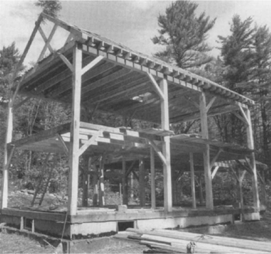
The foundation for the project house need not be substantially different from a conventional house foundation, and a 10- or 12-inch thick concrete wall is fine. It can be a poured, reinforced concrete foundation or it can be laid up with concrete blocks. You also have a choice of either a full basement or a crawl space with a frost wall and insulated flooring and plumbing (I recommend against using a pier foundation except for unheated buildings). I prefer a full basement for routing utilities, a root cellar, and to ensure that the first floor won’t be exposed to winter winds from below—see Huff (1976) for more information. If you have the masonry skills, time, and desire—and the local building codes permit—you could even build a traditional stone foundation. However, in lieu of a full stone wall, you may choose to add a 4-inch wide shelf in the wall above grade to support a stone facing to cover the concrete and give the house a more solid, traditional appearance. The stone foundation walls of more expensive old houses were often faced above grade with brick or sawn stone slabs approximately 4 inches thick and several feet long. Investigate the older houses in your area to determine your regional vernacular. The outside dimension of the foundation must be at least 2 inches larger on all sides than the frame, so add 4 inches to the frame size, which gives exterior dimensions of 18 feet 4 inches by 36 feet 4 inches. If you go with a 12-inch thick wall, add 6 inches to the frame size.
Our project house foundation has a shelf for a stone facing that measures 4 inches wide and 16 inches high.
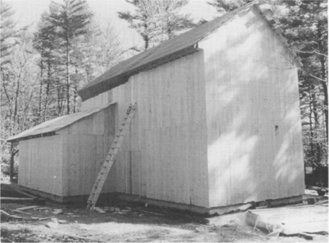
This reconstructed ell is built on a foundation of coursed rubble.
Under all the interior basement posts, place a concrete or stone footing to spread out the load on the soil. This footing should be sized to be adequate for your particular soil capacity. A 3-foot square 12-inch thick footing is usually enough. If the posts will rest on ledge, only a column base of concrete or stone is necessary to keep the post bottom a few inches off the floor and prevent water from wicking up the post from the floor slab.
The frame needs to be anchored to the foundation. In the past, the timber sills merely sat on the stonework. The weight of the house pressing down on continuous sills tied the top of the stonework together. There weren’t any anchors to keep the house from lifting up or blowing off. The substantial weight prevented uplift in all but the fiercest hurricane, tornado, or earthquake. If a house did lift off under such conditions, it might still be intact and able to be put back on the foundation. Had it been rigidly attached as with today’s homes, it would have been destroyed rather than moved. One has to wonder which approach is better! Sill anchors prevent the foundation walls from buckling in under pressure from the earth, which is obviously important; the top of the wall relies upon the floor frame to resist these forces.
There are two effective ways to attach our house to the foundation. The way that is most familiar and appealing to conventional carpenters is to anchor a 2×10 mudsill with anchor bolts. The mudsill lies flush with the timber sills so that the wall planking can be nailed to it at the bottom. Although the timbers of the frame are not anchored directly, the planking should hold the frame to the sill. Another and perhaps easier way is to use flexible steel straps embedded in the wall that can be nailed to the sill timbers. These straps can be bent to conform to the sills and can even wrap around them. Because all the vertical wall planks are nailed to the sills, the house cannot move. The width, gauge, and length of these straps must be sufficient to meet the codes in your area. Check with your code official.
Most codes require that wood touching the foundation be an approved, rot-resistant variety. Although most new houses use pressure-treated lumber, it is environmentally better to use a local, naturally rot-resistant species such as white oak, black locust, black cherry, or cedar. Most of the old timber-framed buildings that I have studied, however, used the same species for sills as for the rest of the frame. Although many old sills have rotted, many also survive that are not of rot-resistant species. I believe that a stone foundation does not draw up as much water to the sills as concrete, so the sills stay drier.
It is easiest to install the floor framing if the foundation is backfilled first. Bear in mind, however, that a concrete wall doesn’t reach its full strength for nearly a month and cannot take a lot of soil pressure; backfill with care. Because concrete is a good conductor of heat, it is probably wise to insulate the wall, and rigid insulation is often applied against the foundation wall before it is backfilled to prevent heat loss. However, consider insulating on the inside rather than the outside. When installed on the exterior, rigid insulation needs some protection where it is exposed above grade, whether covered with stucco or some form of cement board. The insulation won’t be durable like the concrete wall itself and can form a great hideaway for carpenter ants.
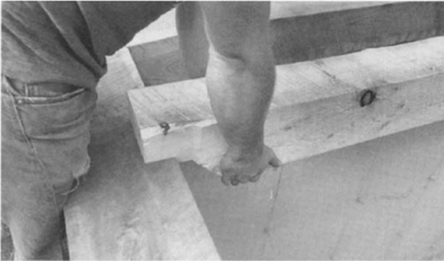
Before the actual raising, the sill timbers and first-floor joists should be set, leveled, and squared. The most convenient way to set the sills is to put them up on blocks from 2 to 4 inches high. This allows you to drive the pins from the top (reference face) and saw them off below. It also allows clearance for planks to roll or slide the sills up if the foundation is not backfilled. Use rot-resistant species for the pegs into the sills. Assemble one of the long sills first on the wall, plug the cross sills into it, and then put pegs loosely in the joints. The two sill girders will need temporary support at their free ends. Forget the basement posts for now. Starting in the middle bay, insert only the tenoned joists into their mortises. You can spread the free end of the cross sills to accomplish this. Put pegs in these holes loosely. Insert the end sills and their tying joists. Assemble the other long sill next to its position on blocks or planks, and then slide it onto the four cross sill tenons, starting at one end of the sill. Insert and drive all pegs until joints are tight and the pegs are resisting. Square up the assembly and at the same time position it equidistant from the outside of the foundation wall on all four sides. Make sure the long walls with the scarfs are straight, too. The assembly can be levered into position with a long pry bar or tapped with a heavy commander (a large wooden mallet). Check for squareness by measuring the frame’s diagonals; when the frame is square, the diagonals will be equal. Nail a long diagonal (a 20-foot long 2×6 is good) on the top of the assembly to keep it square until the sills are lowered onto the foundation wall.
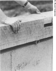
Timbers can be rolled on the wall using pipe rollers.
Starting at one end, pry up and remove the blocks, being careful not to move the assembly sideways. If you are using 4-inch high or higher blocks, lower the frame first onto 2-inch blocks all around before repeating the procedure to lower the frame onto the foundation. Now the top surface of the sills must be leveled. Using a transit or water level, find any high spots (don’t worry about the two sill girders yet). All of the assembly must be shimmed up with cedar shingles to the elevation of the highest spot, and place the shims at post locations, under scarfs, and in the middle of end walls. If there is a crown in these end wall sills, allow enough space for them to settle straight when the floor weight is applied. Fiberglass batt insulation can be stuffed under these sills later. Check the diagonals again for squareness and look over overall positioning and adjust if necessary. Bend the sill anchors up (if appropriate) and nail them into the sides of the sills.
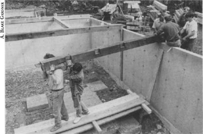
Walk the center sill girders across the basement on a scaffolding of sawhorses. The free end needs temporary support until the other longitudinal sill is in place.
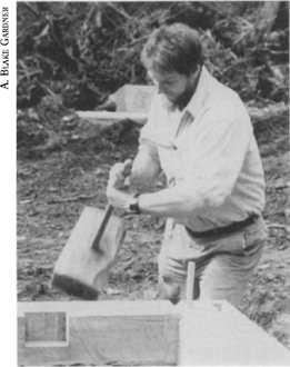
Make minor adjustments to the sill framing using the commander.
The basement posts go in now. You want the post bottom off the finished basement slab by at least a couple of inches to prevent moisture wicking. The simplest support is a squarish stone, at least 6 inches high, on the footing under the post that is wedged up tight to the post bottom until the sill girder is level. Later, when the slab is poured around it, the stone will be anchored in place. With the weight of the house on it, the post bottom will conform to the irregular surface of the stone and be unmovable. If you live in earthquake- or hurricane-prone areas, you might use an anchor strap here also.
The remainder of the floor joists can now be inserted into their pockets. Start both ends in at the same time. You now need some sort of temporary floor to work on. You could apply the subfloor now, but if it is dry, seasoned material you are taking a chance. A good soaking rain can cause subflooring to heave and buckle. I prefer to use loose boards or planks as a temporary floor. After the roof and walls are on, a good subfloor can be installed without risk. If you use 1-inch thick boards, use a double layer for extra strength during the raising. The future roof and attic floorboards or wall planking could be used. Be sure the openings in the floor have good solid coverage.
If the house site is muddy, pick up some hay bales from a local farmer and spread the hay around the foundation and work area. Hay does wonders in keeping muddy footprints off your house frame.
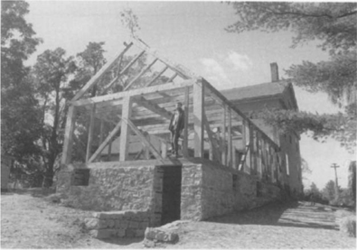
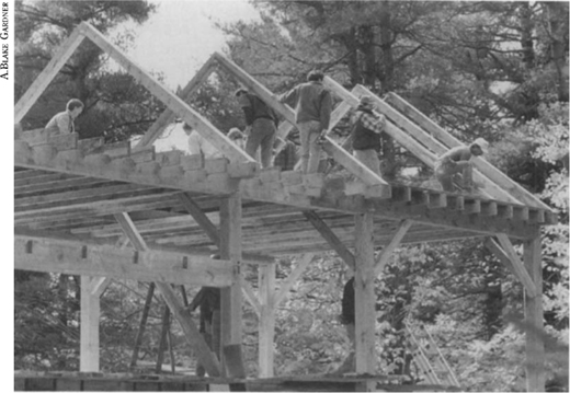
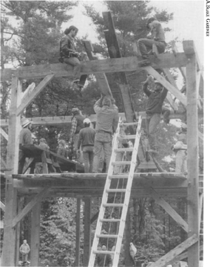
I like to have as much of the frame preassembled before the raising as possible. Preassembly makes the house raising go faster and that keeps everyone interested. The four bents or crossframes can be assembled on the deck in reverse order of their raising. The last bent to go up is assembled first. Because the bents are taller than the space between them, they cannot all be preassembled on the deck with post tenons next to their respective mortises. If the site permits, it may be easiest to assemble the two end bents on blocks or sawhorses on the adjacent ground. Since the reference face would be down, the pegs should be driven from below. If the land slopes off too much, raising bents this way isn’t feasible. In the photos of the house raising, the height of the deck off-grade made it necessary to assemble all bents on the deck. Two of the bents had to be moved along the deck as they were raised.
When assembling bents, first put the girding beam up on blocks, which allows pegs to be driven through and keeps the bents cleaner. Then put braces into the girding beam and slide the posts on their tenons. Peg all connections. Drive pegs from the reference side until they are tight. They can be driven more later so don’t saw the ends off. Position the post bottom tenons next to their respective mortises where possible.
Once the sills are squared and leveled, the remainder of the joists can be inserted.
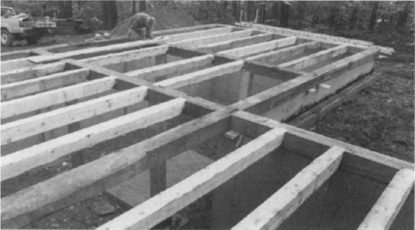
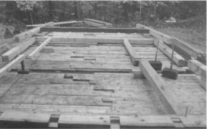
The floor frame is complete.

Install a temporary floor to provide a footing during the raising.
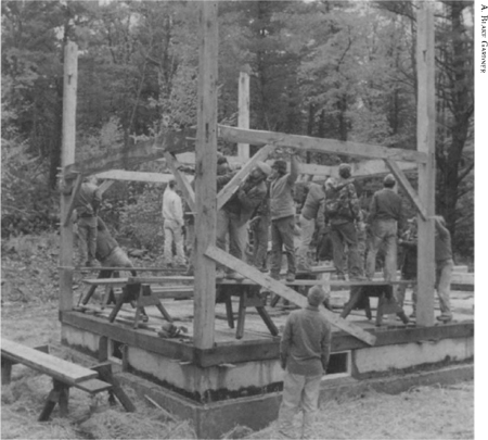
The bents are assembled and ready for the raising.
Organize the remainder of the timbers so they are readily available when needed. Identification numbers should be up. For raising day, you need a pair of heavy pry bars, six sawhorses, staging planks (at least six 2×10s that are 8 to 12 feet long), two 2×6s at least 10 feet long, two 50-foot lengths of ½-inch manila rope, a commander, and possibly a come-along if joints are going together tightly. You can make your own commander from timber cut-offs (lots of knots are fine) and a tapered replacement shovel handle. Drill a hole through the head — usually about 1½ inches wide — and insert the thinnest end of the handle first. The thick end will wedge itself in the head and tighten with use, much like the handle of a pick ax.
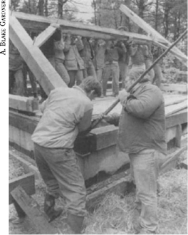
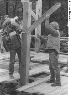
The post bottom is guided into its mortise; a long bar prevents the bent from sliding off the deck.
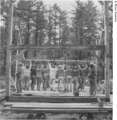
I usually schedule a raising for a Saturday with the following Sunday as a rain date. As soon as enough helpers arrive, the raising begins and moves quickly. Before lifting the first bent, a short speech on safety is imperative. You don’t want this momentous occasion to be marred by an accident or injury. One person must take command and orchestrate the raising, and others must listen for this person’s directions. Individual responsibilities should be given to specific individuals. Dogs, children, and others not directly involved should be well back from the work area. Remove any clutter from the deck. Have a first aid kit handy and know where the nearest phone is in case of emergencies. Don’t forget to not serve alcoholic beverages until the raising is over. Finally, you may wish to invite any experienced framers in your area to lend their raising expertise.
On top of the two tall posts, loop a rope to use as a tag line to keep the bents from going over. One person should be positioned at the foot of each post to help hold the post bottoms and to guide the tenons into their respective mortises. Those at the main posts should have a long (at least 4 feet) pry bar in the mortise to keep the post from sliding. Those lifting the bent should be lifting straight up and walking forward as they do but there is invariably a tendency to push the bent horizontally as well. The person using the pry bar resists this force. It would be disastrous if the end bent was to slide off the deck as it was lifted. The pry bars also guide the tenon into the mortise but the bar is withdrawn before it becomes pinched in the joint. Occasionally the post tenons do not engage as the bent is lifted, but as long as the posts are not off the deck, the bent should be raised vertically. With a few taps of the commander, you can align the tenons with their mortises and the post will drop 2 inches with a resounding thud. Start at one end and work toward the other, keeping toes and fingers out from underneath posts. Working one end at a time, plumb the post on the reference face with a 4-foot level and securely nail at a minimum a 10-foot 2×6 diagonal brace from the post down to the deck at about a 45-degree angle. Avoid covering any joints or peg holes. These braces should be left on until the plates with their braces are on.
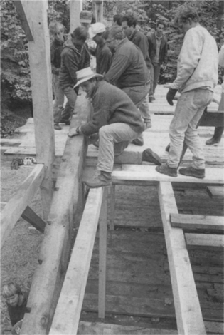
The second bent follows. When it is vertical, the tying joist and the two girts with their braces need to be inserted. Set up a pair of sawhorses with planks across them under each of the members. Then three or four helpers standing on the planks can insert the members. When all are engaged, push the bents together—assisting with the commander as necessary—and peg all connections. The other joists can be dropped in at this time.
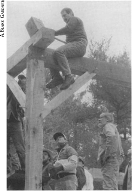
Continue with the other two bents until the second-floor framing is complete. The second floor should be covered with loosely laid planks or two layers of boards. The future wall planks are fine for this. Leave a sufficient hole in the middle of the floor to pass up long timbers. The plates are next. Set up a continuous scaffold on sawhorses along the front posts. The plate sections are first carried onto the first-floor deck, then passed up through to the second-floor deck and set on the staging on blocks. The plate section with the lower half of the scarf is, of course, put on first. The bridled scarf was chosen to allow the plate sections to be inserted separately. With some other scarfs, such as a bladed scarf, the plate would be assembled first and then lowered on the posts. With as many hands as room allows, lift the plate onto the posts and engage each tenon as it is lowered. Should the posts have bows, a smaller bar can be used to align the joints or try a couple taps with the commander. Repeat for the other plate half and then set up your equipment again and do the opposite side’s plate. Peg all these joints.
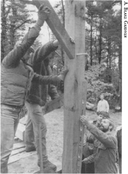
Each post is plumbed and a temporary diagonal brace is nailed on to secure it.
The second bent is raised. Note the two pike poles.
The girts with braces and the tying joists must be inserted between the bents. Planks set on saw-horses make convenient staging.

All the remaining floor joists are fitted.
A temporary flooring of planks is laid to make work above the second floor easier.
In preparation for raising the plates, braces are installed and pegged to hold them in position.
The plates are passed up through the floor.
Each plate is lifted onto post and brace tenons. Planks over sawhorses are again used for staging.
The tie beams follow the plates. The commander can be used to seat them.
The attic level framing is next. Set up the sawhorses and planks to provide a staging to lift each tie beam starting with end tie beam 1. The plates may have to be spread or pulled together to align the dovetailed lap joint. Keep moving the staging east and insert the attic floor joists as you go. The chimney opening framing is easily installed by spreading the joists. I suggest that you add a few 20d (or “20 penny”) spikes to keep these joints tight. For convenience, put on the last tie beam before the last three joists. It can be set on the plates and can slide along until it drops into its dovetail.
With the attic framing complete, boards can be laid to provide a working platform for the roof structure. First, insert the rafters with the tenoned bottoms and peg them, remembering that the mortised rafters are on the north side. The raising planks are cut to length and fitted between them. Align a straight, nonwaney edge so that it just touches the top plane of the rafters and spike it to each joist and the tie beams with two 20d (4-inch) common nails. Once the raising plates are fastened, all the rafters can be added. The common rafters are centered above every other attic floor joist and each one is spiked to the raising plate with three 20d common nails. The center opening between the rafters must be 32 inches wide to allow for the chimney. To achieve the straightest roof plane, stretch a string across the truss rafters near their lower end and slide the common rafters until they just touch this string. Check to see if the peaks are also in line. When all rafters are up, they need to be plumbed and spaced properly. Plumb the first rafter with a long level or plumb bob and nail a board brace on its top side to the lower end of another rafter at about a 45-degree angle. Then, measure from the outside of the building to each rafter’s reference side at its foot and make the distance the same at the peak. Nail a board parallel with the ridge across the rafters to secure the spacing. Add another opposing diagonal brace at the opposite end. These braces and spacing boards stiffen the roof until the board sheathing is applied. Once one side is sheathed, the braces are removed and the other side is sheathed. Nail a small evergreen tree to the peak at one end to give thanks to the forest for providing such a wonderful, useful material as wood, and let the celebration begin.
Pike Poles. When tall barn frames were raised in the past, helpers would use pike poles, which are 2- to 3-inch diameter poles up to 16 feet long with a spiked point. As the bent was raised and passed from reach, those with pikes jabbed them into the upper timbers to help push the bent up. Our house frame can be raised without pikes because the bents are not out of reach. If you have pikes available, it would be helpful to have one on each of the tall posts. Those holding the pikes should have enough control so that if the bent jerked and a pike dropped down, the pike can be kept from hitting someone below.
Work from one end of the building to the other when installing the joists and tie beams.
The principal rafters are inserted first and pegged. The raising plates are then cut to fit and securely fastened. Common rafters are then nailed to the raising plate. Allow enough clearance between the central rafter pairs for the chimney.
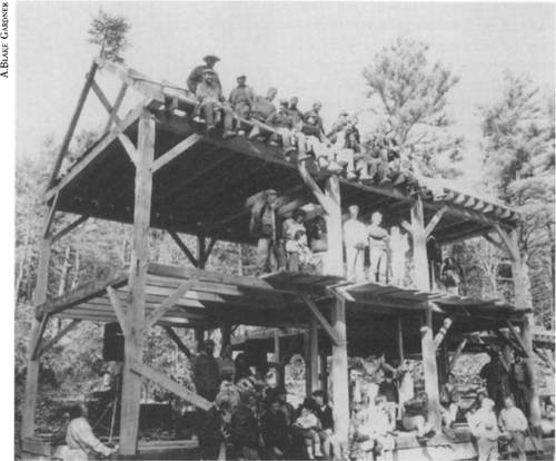
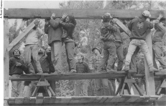
After attaching the traditional evergreen bough to the peak, helpers pose for a picture on the finished house frame.
Using a Gin Pole. This house can be raised safely without the benefit of a big crew in a manner that is as old as the art of building itself. The gin pole (gin is the root of engine) is a simple but ingenious method of lifting loads vertically. You need a strong, straight, relatively knot-free pole about 10 feet longer than the highest lift. On our frame, a 32-foot pole should do. The tip should be at least 5 inches in diameter and the butt perhaps 8 inches. The pole is guyed nearly vertical by three guy lines anchored to immovable objects. The top of the pole should lean so it lies almost directly above the object to be lifted. I say almost because the guy lines will stretch some and cause the pole to lean more as the object is raised. Two guy lines should angle back to hold up the pole while the third acts as a stay to keep the pole from tipping over backward should the load swing toward it. At the top of the pole, leave a branch stub to keep the lines from slipping down the pole. If there is no stub, bore a hole and insert a peg with a 1-inch or larger diameter. The rope that the tackles are hung from is looped around the pole a few times above the branch stub. All lines that attach to the pole should be looped around the pole in such a manner that they tighten as the load is applied. The butt of the pole can sit in a shallow hole in the ground or can rest on the floor decking. If the pole rests on the deck, be sure there is adequate support below and enough anchorage to the deck to keep the pole from sliding, although most of the force is straight down.
The block and tackle provides the mechanical advantage necessary for limited muscle power to lift heavy loads. The more pulleys in each block, the easier the lift will be. For instance, using two double-pulley blocks with one block having a shackle to attach the end of the rope to gives you nearly a 4-to-l advantage (some energy is lost to friction). With two triple-pulley blocks, you have nearly a 6-to-l advantage. Of course, the more pulleys involved, the longer the rope must be. To determine the mechanical advantage of the setup, count the number of lines supporting the lower block. Five lines means about a 5-to-l ratio. The line coming out of the upper block that you pull on should be passed through another pulley anchored at the base of the gin pole. This pulley doesn’t change the mechanical advantage, only the direction of the pull. On a downward pull, two or maybe three people can effectively pull. With a horizontal pull, numerous people can pull in line.
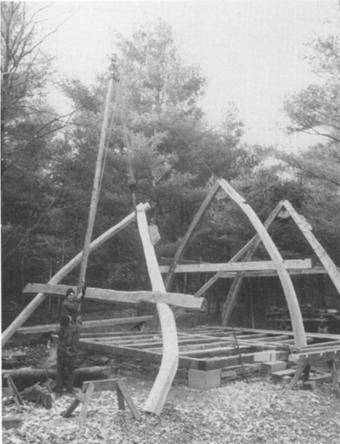
The gin pole is a marvelous device for lifting heavy objects safely and without strain. This 30-foot long spruce gin pole allowed only three men to raise this cruck frame.
The main drawback to the gin pole is that it has to be moved for each lift. Because of this and the extra setup time, I only use a gin pole if a hand raising won’t work, such as when lifting trusses or very tall bents.
As soon as the frame is topped off, tackle the roof. Completing the roof protects the frame from rain and from drying too quickly, keeps water out of the basement, and gives you a dry place to work in the rain. One of the advantages of having an unheated attic below the roof is that the house can be roofed more quickly and with less expense than insulating on top of a timber-framed roof.
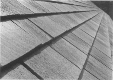
I suggest a roof sheathing of 1-inch rough-sawn boards. They can be waney, green, low-grade boards of virtually any species. They can even be random widths and lengths. They should, however, be at least 6 inches wide and 8 inches is better. Start on the side of the roof without the temporary bracing and lay them as tightly as you can without being fussy. If the boards are laid green, gaps will widen as they dry and shrink. The gaps are good for ventilation. Allow the proper overhangs on both the eaves and gable ends. To avoid setting up a scaffold to board the roof, work from the inside. The chimney opening allows even the last boards to be installed that way. For the roof, sawn wood shingles are recommended.
If you must buy your shingles, western red cedar is the best choice. Use 18-inch shingles with 5½ inches to the weather, which is triple coverage. However, they can also be sawn from your own trees with little impact on the environment. The traditional choice in much of New England is eastern white pine. These pines grow with a whorl of branches added each year, and healthy trees grow between 6 inches and 4 feet in height annually. You want to cut your shingles in the clear wood between these whorls. If you are selecting trees for shingles, pick larger specimens with whorls spaced about 2 feet apart. Since most shingle sawmills need squared balks to work with, first saw logs into the largest timber that has mostly heartwood. Then saw the logs in half right through the pith, which provides mostly radially sawn shingles, and radially sawn shingles are less likely to warp. Next, measure out 18-inch clear wood billets between the whorls. If some whorls are less than 18 inches apart, saw the billets at 18 inches anyway and keep the knots at one end. These billets will still provide some usable shingles.
Traditional wall sheathing for a plank house is full-height planks that are 12 to 20 inches wide and at least 1¼ inches thick or, more often, 1½ inches thick. In my area, spruce, hemlock, and pine were the common choices. They were roughsawn and probably unseasoned. Because of their great width, the nails wouldn’t let them cup. They might split, but that would hardly affect their performance. Today, full-height planks of such width are hard to procure and expensive. You could use wide planks that are only one story in height or 2×6 or 2×8 tongue-and-groove planks, which can be milled locally or purchased from the lumber yard. If you purchase the planks from the lumberyard, use a commercial grade for economy—the planking will not be seen anyway. The tongue-and-groove joints keep the planks acting as a unit.
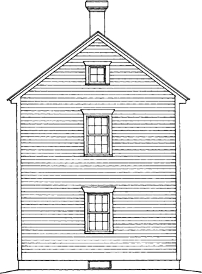
After the planks are up, you can mark your rough window and door openings using a level. Locate rough openings the proper distance off your floor so that the finish height inside the jamb is 6 feet 8 inches. Rough openings are usually 6 feet 10½ inches off the subfloor. The fenestration (window and door arrangement) seen in the photos and drawings is very traditional, but you may opt for something more contemporary. Keep the corners of the windows tight to the braces. To stiffen an opening and provide nailing on the outside for the furring strips, nail a flat, full-sized (rough-sawn) 2×4 around the exterior of the opening.
The wall planking can be installed with or without first framing window and door openings. You will save lumber, however, if you frame them initially.
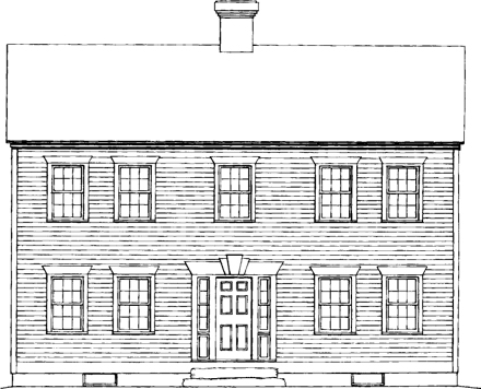
These front and side elevations show traditional fenestration for a hall-and-parlor house.
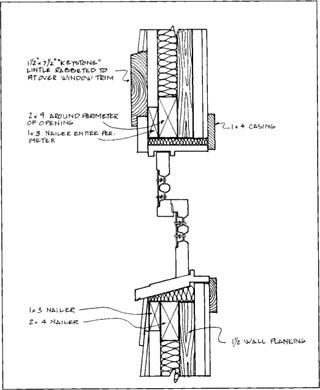
A VERTICAL SECTION THROUGH A WINDOW
You can build your own plank door with battens. Use a rot-resistant species for the sill, frame, and door. You could install a used door if you like. Plan your rough opening appropriately. Some old houses had very extravagant entries, and if you have woodworking skills you might want to try one. If you choose a new door, choose a solid-wood one. Solid wood wears more gracefully than metal or plastic. Add a storm door (with divided lights, of course) to protect the door.
Over the wall planks we must install a vapor barrier or retarder because the building codes require it. I’m not sure if we really do need one—warm, cozy buildings have been built without them for thousands of years. There is also some debate on how long they actually last inside the wall. Are they permanent enough for as permanent a dwelling as ours? These sorts of products are constantly changing, so do your homework before deciding on one.
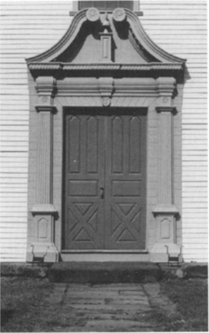
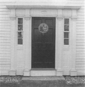
These fancy entrances are found at Old Deerfield, Massachusetts.
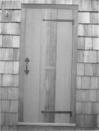
Simple and strong plank doors are often the most economical entryway choice.
Over the vapor barrier, put your rigid insulation. The furring strips that the siding is nailed to hold the insulation in place. The practical thickness for the insulation is 2 inches as the nails holding the furring strips must penetrate it. I use 16d box nails. If you must use more insulation, add some nailers—2×3s on edge (if rough-sawn) would allow 3 inches of insulation. The insulation used in our project house was rigid fiberglass. It wasn’t chosen because it is highly efficient (its R-value is 8.7 for a 2-inch thickness) or because it is cost-effective. Rigid fiberglass breathes, doesn’t use CFCs, isn’t prone to attack by carpenter ants, and isn’t made from fossil fuels. Carefully consider your choices of insulation—it may be one of the more important building material decisions that you make. You must weigh such factors as efficiency, durability, economics, and environmental friendliness. By the time this book is printed, there may be some new (or old) insulation solutions developed that answer all the criteria superbly.
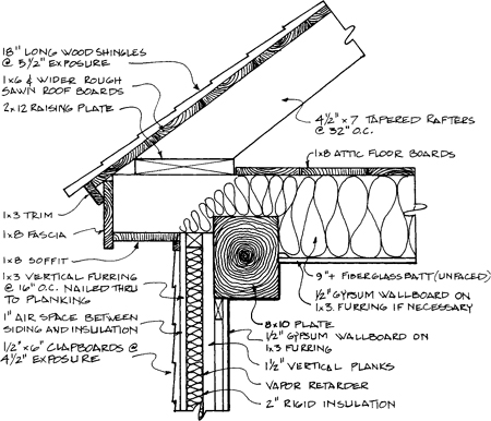
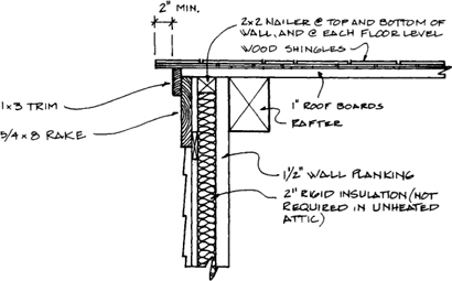
A WALL SECTION AT THE CORNICE
There is an alternative to insulated walls. First, you could build the house without the vapor barrier, furring, and insulation. With lath and plaster on the inside to keep out drafts, a 1½-inch plank wall with clapboards will have an R-value of less than 5. If you don’t keep the house above 60 degrees in the winter and if you burn your own wood for fuel, you can probably get by. Many older plank houses had thicker planks—up to 4 inches thick—which gave an R-value of about 8. That’s still not great, but the walls do begin to function more like a log house, becoming a heat reservoir that stores the sun’s heat during the day and slowly releases it at night. A massive plank wall performs better than its R-value might suggest. For ease of handling, I propose using two layers of planks with the joints staggered.
There are several options for the siding: shingles, clapboards, vertical shiplap boards, board and batten, diagonal boards, and even stucco. The exterior finish you choose should be based on those materials available in your locale and what is or was common there historically. If you are building on Cape Cod, for instance, white cedar shingles are probably the most appropriate. In the hill towns of western Massachusetts where I live and work, native red spruce or white pine clapboards are the traditional choice. A few houses from the 1700s still have the original clapboards fastened with wrought nails, and some haven’t seen a coat of paint for at least one hundred years. These aren’t the clapboards that we find at the lumberyard today—they were not sawn with a taper. A common size was a rough-sawn ½×6. Occasionally, opposite corners might be tapered back a few inches with a plane to lay flatter. Because they were cut from the primeval forests where trees grew slowly, there was little if any sapwood on them, and heartwood will not rot if given adequate light and ventilation. Instead, these old-style clapboards wore away gradually and produced those wonderful furrows and colors that we treasure.
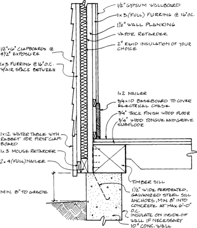
A WALL SECTION AT THE FOUNDATION
A SECTION THROUGH THE RAKE
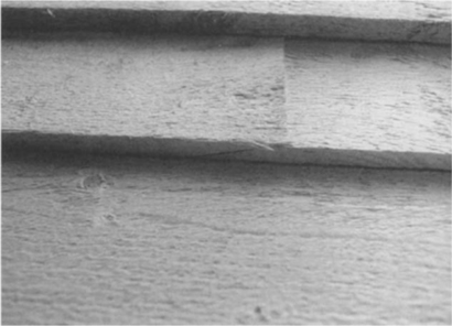
Traditionally, clapboards were scarfed at their ends where they join.
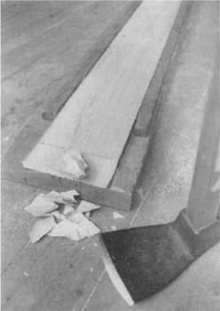
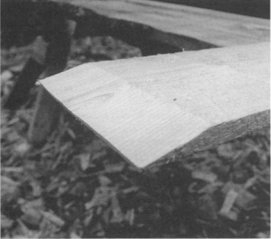
This scarf was cut with the adz in about 15 seconds while the jig held it in place. One foot is placed on the clapboard to keep it from sliding.
Installing Clapboards. Clapboards are nailed over vertical furring strips every 16 inches on center. Nailers are also provided around windows and doors or wherever the ends need support. At the bottom of the wall, a wide board called a water table could be installed and the first clapboard fitted over it, although in the house photographed here the owner didn’t use one. If you omit the water table, install a continuous strip of wood to cant out the first clapboard. This strip or the water table also serves to keep mice and bats from inhabiting the air space behind the siding. Six-inch clapboards are typically exposed 4½ inches, but this can be changed slightly to end up with a whole clapboard below a window instead of one nearly cut through.
Today, carpenters merely butt clapboards at their ends and waterproof the joint with a piece of asphalt-coated paper below. On houses from the eighteenth and early nineteenth centuries in my area, clapboards were adzed to create a scarf where they join. The scarf was typically 2 inches long, which is the width of the blade of the framing square. In this way, the clapboards truly shed the water. This scarfing sounds like a painstaking detail but it actually goes quite quickly. On the spruce clapboards for my workshop, each end was adzed in about fifteen seconds. Be sure that you locate the scarf in clear grain. One reason why today’s carpenters use the square butt joint is that a scarf of the type described is not easy to cut with power tools, a problem compounded by the tapered clapboards common today.
When I was planning my house some years ago, I fully intended to live there without electric power. I thought that if I did eventually want power, it would be produced on-site. I have softened a bit over the years and the house is completely wired and connected to the grid, but I am not a big user of the stuff. In addition to the lights, water heater, and pump, I have backup electric heat to keep my pipes from freezing when I leave town in winter for a few days. Because I hadn’t planned on getting electrical service, the meter and drop ended up being right next to my front door. Although I don’t like the looks of it, at least I take notice of how much power I am using when I pass it.
Before you automatically install your electric service, give it some consideration. Do a little research into the effects of electromagnetic fields on health. Decide if you really need and want power. If you do, maybe it can be produced on-site (from wind, solar panels, water). By making intelligent siting choices and a few life-style changes, you can eliminate many of the items that require power. If there is a water source uphill of the house, a gravity-fed water system can replace the water pump. If you can your produce and have a cold cellar, you won’t need a refrigerator/freezer. If sited to take advantage of solar heat gain, you can heat your house and hot water with the sun. If you do all you can to replace electric-powered devices but you still need electricity, at least you won’t be using as much. The smaller the load, the easier it will be to produce it on-site.
If you tie into the grid, use the smallest amperage service that you can. As the cost of electricity skyrockets, it’s likely our need for it will diminish rather than increase. Finally, don’t repeat my mistake—plan where the service will come in!
Wiring a timber-framed house is a bit different than a conventional one. For each different exterior-wall enclosure system, there is at least one different preferred wiring system. For our plank-walled house, exterior walls have the wiring on the inside to keep the wiring from piercing the insulation/vapor barrier envelope. The easiest system provides an electrical chase behind a baseboard or wainscoting. Since the interior walls are conventional 2×4 stud-framed walls, try to locate most of the wiring there. If possible, put wall switches and wall-mounted lights there. Use surface-mounted wiring (Wiremold) for fixtures on exterior walls. If used sparingly, it is unobtrusive.
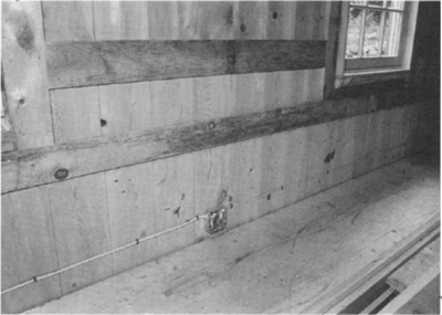
In this house, the wiring in the kitchen/dining area will be covered by wainscoting. In the rest of the house, the wiring runs behind a baseboard. The 1-inch furring strips that span the planks can support wallboard.
If you locate the clapboard scarf in a clear section of wood, your work will be easier.
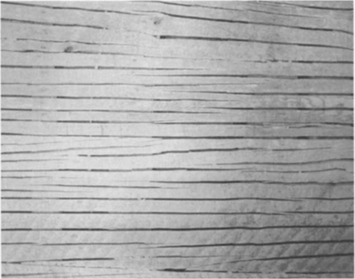
Accordion lath was made from thin boards that were split and stretched out over a wall. The riven edges provided good keying for plaster.
In traditional plank houses, lath and plaster were applied over the interior of the planks. Lath was made up of wide boards approximately ½-inch thick that often spanned the length of the room. Originally, lath was riven and expanded to cover the wall. Because of the way in which the laths were riven, it was called accordion lath. The riven edges formed great keys for holding plaster. This horizontal lath nailed across the planks stiffened the wall, as did the clapboards on the opposite side. Thus, the wall plane acted as a unit rather than as lots of individual planks, forming an eighteenth-century version of plywood sheathing. Builders applied a three-coat plaster finish made from lime, sand, and hair over the lath. Later, gypsum plaster became standard. Lath and plaster were a wonderful system. The lath was sawn from local timber, the plaster was often produced locally, and area craftsmen did the work. This lath-and-plaster system can certainly be used on your house. It is, of course, labor intensive compared to gypsum wallboard, and plastering is perhaps best accomplished by professionals. However, should you choose to do it yourself, you need not achieve a perfectly flat surface. The resulting textured wall is actually more appropriate to a timber frame. However, most will probably opt for gypsum wallboard as it is indeed faster. For wallboard, run horizontal 1×3 furring strips every 16 inches on center over the planks and around all edges and at timbers. In lieu of the traditional lath, furring strips will stiffen the planks. The finish wall will extend out 1½ inches, concealing some of the timber framing. Some concealment is actually more authentic looking for old-style houses. Where the wallboard butts the timbers, you can either run taping compound right up to the timbers or tape to ½-inch L-bead. The L-bead is a metal strip nailed over the wallboard, much like corner bead, that is taped over and concealed, making a clean, straight edge when the timber shrinks away from the wallboard. Leave off the wallboard at the base of the wall for the baseboard electrical chase.
For the interior partitions of our house, conventional 2×4 stud walls were used to facilitate wiring and plumbing and gypsum wallboard covered both sides. In old plank-on-timber frame houses, interior partitions were composed of wide planks nailed to the sides of floor and ceiling timbers. These were lathed and plastered on both sides creating a wall about 3 inches thick. The disadvantage of this old system is that there is no cavity to conceal pipes and wires. Since the timber frame is designed to carry the floor loads, these interior partitions are not load-bearing.
If the attic floor joists are rough sawn, they will likely vary in depth. If you install a traditional lath-and-plaster ceiling, you probably won’t have to do any shimming. If you use gypsum wallboard, however, you may wish to furr the ceiling with 1×3s shimmed level. Although wallboard over furring lowers the ceiling a little, it provides more space for insulation. If the joists are consistent in size, furring may not be necessary.
Some building codes allow you to omit the vapor barrier in the ceiling if the attic is ventilated. If we use board decking with wood shingles, the whole roof surface allows air movement. I would opt to omit the vapor barrier here if your codes permit it so that the house will breathe, vent any toxic vapors, and decrease the interior humidity level.
For ceiling insulation, I suggest either loose-fill or batt-type insulation. Mineral wool batts (fiberglass), cellulose, mica pellets (vermiculite), or even something of your own concoction might be appropriate. Your choice depends on local availability, cost, health risks, thermal performance, and building code requirements.
Because of the floor-joist spacing (every 30 inches on center), you must either use two layers of boards or a single plank with tongue-and-grooved edges that is at least 1½ inches thick if softwood or 1¼ inches thick if hardwood. In the well-to-do old houses, builders often installed wide hardwood planks (or yellow or hard pine) with tongue-and-grooved edges. The tongue-and-grooved edges stiffened the floor by spreading the load onto adjacent planks and also kept some of the dust from filtering through the floor. In common houses, a two-layer system without the tongue-and-groove was used. The joints were staggered to add strength and to keep the dirt from filtering through. The boards were face-nailed with wrought or cut nails.
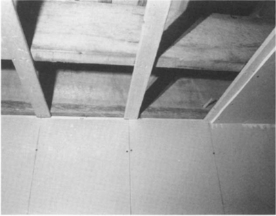
The wallboard ceiling is fastened to 1×3s every 16 inches on center. Use shims if necessary.
Like electricity, plumbing is one of those things we don’t have to have. But doing without plumbing requires a bigger life-style change than electricity. If you have a composting toilet or outhouse and a hand pump in the kitchen, you can live as comfortably as you would have a century ago. You would have to heat the water and fill the bathtub by hand, but it would make bathing a ritual. In summer you could use a solar-heated outdoor shower or swim in a pond or stream. Before you rule these thoughts out, try staying at a country house without electricity or plumbing for a few weeks. A short time ago, it was seen as backward, but now some see it as progressive.
Because timber-framed homes predate the advent of indoor plumbing, they lack the cavities in the floor to hide such amenities. Fixtures on the first floor can have their plumbing exposed in the basement, but unless you want exposed plumbing in the ceiling of the first floor, you must plan carefully to conceal the pipes for second-floor fixtures. The simplest way is to locate all fixtures over a closet, pantry, bath, or other such space that can have a dropped ceiling. Then channel the piping down to the basement in a 2×6 stud partition. If all the plumbing fixtures are vertically in line, then a 2×6 partition can be located under them. If there is an open room below the bath, you could elevate the bathroom floor enough to run all the pipes above the second floor until they can drop down to the basement via the nearest partition. Of course, this requires a step up into the bathroom. In lieu of a raised bathroom floor, you could lower the second-floor timber framing in that bay about 6 inches so that the builtup floor will be flush with the rest of the second floor.
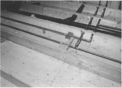
One option for hiding the plumbing in an upstairs bathroom is to raise the floor for a pipe chase. In that case, run 2×6 joists over the subfloor, which will force you to step up into the finished bathroom.
In the areas that supported a northern hardwood forest, beech, yellow birch, and sugar maple were popular choices for the top boards. These species wear extremely well, and rooms seem brighter with their light coloring. Judging by the gaps between boards in some houses, they were laid down only partially seasoned. If you use hardwood flooring use cut-box nails (see Tremont Nail Company in Appendix B) so you won’t have to predrill for each nail. A cut nail, if driven so the shaft is parallel with the grain, will not split hardwood like a wire nail. And, because the nails are visible, the heads on a cut nail are more attractive. The boards need not be clear. Indeed, buying all clear boards would be expensive. For my floor, I purchased rough-sawn mixed maple boards of random width that were “run of the mill” (that is, not sorted or graded). I stacked them to dry outside under cover for at least a year. When I got the roof on the frame, I stacked them inside on the subfloor. Then, just before I was ready to lay the floor, I had them planed on four sides at a local mill. They were ¾ inch thick and ranged from 3½ inches to 11¼ inches wide. Waney edges were placed down, and boards with unsound loose knots were avoided. The floor has a lot of character and I saved a great deal over the typical hardwood floors installed today. With wide boards, the joints between planks open and close depending on the seasonal humidity. Eventually, dirt and grime get packed in these joints and the floor looks like an eighteenth-century floor.
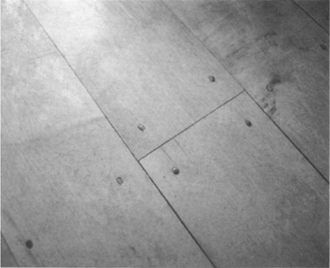
This maple floor is made up of 1-inch thick random-width boards that were planed to ¾ inch after seasoning and face-nailed with cut-box nails. The floor is attractive, durable, and inexpensive.
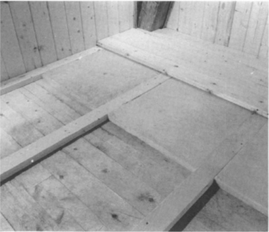
If you lay your floor over an unheated crawlspace, you can insulate between the nailers on top of the subfloor. The finish floor here is 2×6 tongue-and-groove planking.
Some mills that plane boards can also tongue-and-groove edges. Then, if you use the thick stock sizes mentioned above, only one layer will be necessary.
For the second-story flooring, you can use the same system. The second floor’s flooring is also the first-floor ceiling, so you may want to add some sound insulation to make the upstairs more private by installing ½-inch thick structural sound insulation board between the flooring layers. The insulation also helps to prevent dust from filtering through the ceiling. Many prefer softwood floors upstairs because softwoods are softer under shoeless feet and warmer to the touch, though they dent and scratch easier than hardwoods.
The attic floor was a place to use low-grade boards in the past and still is. Builders often laid the flooring quickly using rough-sawn boards with little regard for tight joints. If ever the attic becomes living space, just apply a finished layer of boards over the rough layer.
You will want to apply some sort of finish on your flooring to prevent staining. Though there are some very durable commercially manufactured finishes, I recommend using a natural finish. Many people that have been bombarded with chemicals for years have become sensitive to outgassing from these synthetic finishes. Sources for natural and low-odor synthetic finishes can be found in The Healthy House (Bower 1989).
When choosing finishes for any part of the house, try to select the healthiest, most environment-friendly products available. Remember that your house will last for many generations.