11
Modeling and Evaluating the Environmental Degradation of UHTCs under Hypersonic Flow
Triplicane A. Parthasarathy1, Michael K. Cinibulk2, and Mark Opeka3
1 UES, Inc., Dayton, OH, USA
2 Materials and Manufacturing Directorate, Air Force Research Laboratory, Wright-Patterson AFB, OH, USA
3 Naval Surface Warfare Center, West Bethesda, MD, USA
11.1 Introduction
Over the past decade, a worldwide interest has grown in developing aircraft that can travel at or greater than Mach 6 [1]. Several short-duration flight tests by NASA and the U.S. Air Force have shown that a scramjet engine can be used to achieve aircraft speeds of Mach 5 to Mach 10 [2–4]. Extending these concepts toward the development of a vehicle for reusable or sustained flight now awaits the development of novel materials that can handle the aerothermal conditions imposed on some of the critical parts [5]. The sharp leading edges of the vehicle and cowl at the engine inlet as well as the fuel injection struts in the combustion section of the scramjet engine are considered to be critical components with anticipated material temperatures that could reach as high as 2000°C through aerothermal heating at Mach 8 [6]. These components are required by current design to have a geometrically sharp leading edge (762 μm or 30 mil radius of curvature) that must be retained while bearing the extreme environment resulting from hypersonic flight. Both material development and modeling activities toward such an application were carried out in the 1950s and 1960s.
The conditions experienced by a sharp body under hypersonic flow were initially modeled by scientists at, and/or funded by, NASA [7–12]. Material development and modeling efforts were pursued under Air Force funding by Kauffman et al. [13–17]. Based on the promising results from prior research and the recent worldwide interest for hypersonic aircraft development, a renewed effort has commenced in research and development of ultra-high temperature ceramics (UHTCs), which are typically defined as nonoxide ceramics with chemical and structural stability above 2000°C [18]. Environmental degradation and especially oxidation under hypersonic flow conditions are widely recognized as key life-limiting factors for leading-edge applications [18–21]. Thus, studying the oxidation kinetics and tailoring compositions to improve oxidation resistance have been the focus of the most recent work.
The most studied UHTC compositions are diborides of hafnium and zirconium with additives to control grain growth and/or improve oxidation resistance, the most common being SiC. The environmental response, especially oxidation, has been evaluated using several different methods. The most common has been the measurement of oxidation kinetics in a furnace atmosphere under isothermal conditions [18, 22–31]. Methods that also impose realistically high heating rates include arcjet testing [32, 33], laser-based heating [34], electric heating [35, 36] or oxyacetylene torch testing [37], and exposure inside a direct-connect scramjet engine [38–40]. Among these, arcjet testing is the most widely used historically by the Air Force and NASA for simulating reentry conditions. However, none of the tests used to date, including the arcjet test, reproduce the actual conditions that a leading-edge material will experience during hypersonic flight. Key parameters that represent these conditions with respect to material survivability are heat flux, total or stagnation temperature, total or stagnation pressure, dynamic pressure, fluid velocity at the material surface, fluid composition, degree of dissociation of gaseous elements, and catalytic recombination at the surface of the material. In addition, under realistic conditions, resistance to acoustic and mechanical vibrations and thermal shock will also be important. Most of the oxidation experiments described in the literature are conducted in laboratory furnaces, thus assigning total temperature as the key parameter of interest by default with all other factors ignored. Tests that use a laser as the heating source focus on reproducing the appropriate heat flux and, in some cases, include fluid flow. Arcjet tests generally focus on reproducing the heat flux, a significant fraction of which depends on catalytic recombination of gases, which itself varies with material surface chemistry and morphology. The scramjet rig reproduces several of the aerothermal conditions predicted to be experienced during free flight, but it uses gases that differ in chemistry from air, and the actual gas flow velocities are not sufficient to cause dissociation of gases behind the bow shock.
The lack of an accepted test to evaluate the suitability of a candidate material for hypersonic applications has necessitated the need to develop models to interpret and compare experimental data from the various testing techniques. Such models would then enable the prediction of performance in actual hypersonic environments. Advances toward this objective are presented in this chapter. Figure 11.1 is a schematic that summarizes the approach that has been taken to address this objective. Progress in environmental modeling efforts, their limitations, and possible future directions are discussed.

Figure 11.1. Overview of the approach used to model and evaluate UHTC leading-edge materials under simulated hypersonic flow conditions by Parthasarathy et al. [39, 40, 51–53, 57].
11.2 Oxidation Modeling
The ideal model for oxidation kinetics of UHTCs will be able to include all of the control parameters of the experiments as input and predict any of the various parameters measured as outcomes of the experiments. Further, the model will be able to translate data across different testing techniques and use them to predict performance in an actual application. Thermodynamic modeling of the oxidation process is the natural starting point in the development of such a model, since it will involve the least assumptions and could be considered as modeling from first principles. It also provides information on key chemical species that will clearly guide kinetic modeling. In the literature, relatively simple yet elegant oxidation kinetic models have been identified, such as the classic parabolic scale growth model formulated by Wagner with or without accounting for evaporation of scale at the surface [41, 42]. However, UHTCs have been found to form a complex scale that is heterogeneous and defies the use of simple models. In particular, the complex morphology, chemical composition, and nature of the scale formation require modifications to the Wagner model. Further, parameters that affect the kinetics require material properties that are not readily available or known with certainty. Thus, models for oxidation kinetics of UHTCs can be expected to include approximations. Given these difficulties, it is best to think of the resulting model as a methodology to interpret data rather than one derived from first principles. For this approach, a large database of experimental results is useful. Fortunately, a large body of oxidation results is available in the literature from the 1960s, which is described briefly before modeling concepts are presented.
The oxidation behavior of transition metal diboride-based UHTCs has been characterized using a variety of methods and approaches. The earliest research identified the diborides of zirconium and hafnium as the best performers with respect to oxidation in flowing air at temperatures above 1600°C [13, 15, 16]. Later studies included composition modifications, which resulted in the conclusion that HfB2–20 vol% SiC was the most oxidation-resistant UHTC at the highest temperatures. These studies utilized furnaces, forced flow air heaters, and arc heaters [17, 43]. This early research also included tests on leading-edge geometries of candidate materials using arc heaters [44]. These were followed by more careful studies in air or argon–oxygen mixtures in furnaces as well as thermogravimetric analysis (TGA) [22]. Typically, these evaluations reported scale thicknesses and sometimes recession rates, while TGA studies reported weight gain and weight of oxygen consumed as a function of time and temperature.
Oxidation studies on the most promising diborides were reinitiated in the 1990s [26, 31]. Much of the data reported on oxidation kinetics since then has been on the zirconium and hafnium diborides with SiC and other additions [18, 26, 30, 45–47]. The first modeling efforts were undertaken by Opeka et al. [18] and Fahrenholtz [48, 49]. Opeka et al. derived condensed/vapor-phase equilibrium diagrams for the Zr–O, Si–O, and B–O systems at 2227°C and assembled them to gain a thermodynamics-based description of the oxidation of the ZrB2 + SiC composition, which provided insight into the synergistic benefit of each oxide in the multicomponent scale. While pure SiO2-scale-forming materials (e.g., SiC) are limited to an approximately 1800°C usage due to the onset of active oxidation, the invariant vapor pressure of B2O3 with pO2 was proposed to play a significant role by mitigating the active oxidation of the SiO2-forming component above this temperature. This study was followed by the work of Fahrenholtz who derived the volatility diagrams for ZrB2 at 1000, 1800, and 2500 K [49] with the PO2 calculated for the equilibrium coexistence of ZrB2, ZrO2, and B2O3, in contrast with the unit activities assumed by Opeka et al. His work provided an expanded thermodynamics-based description of the Zr–O and B–O condensed/vapor-phase reactions and associated vapor pressures as a function of the three selected temperatures (1000, 1800, and 2500 K) and showed that B2O3(g) was the favored gaseous species at temperatures and pressures of engineering interest (Fig. 11.2a). He further provided a temperature-dependent, vapor pressure-based description of the B–O system to gain insight into the weight fraction of liquid B2O3 retained in the condensed but porous ZrO2 scale. The retained B2O3 was also experimentally determined by Talmy et al. [50], and their results are shown in Figure 11.2b (graphically) and 11.2c (microstructurally). Fahrenholtz expanded the thermodynamics-based analysis to the ZrB2–SiC UHTC composition and proposed a reaction sequence for the oxidation process, associated scale composition and growth, and formation of a depleted zone of the SiC phase in the base ceramic [20]. These largely thermodynamics-based efforts were followed by the development of an oxidation kinetic model of these refractory diboride UHTCs by Parthasarathy et al. [51–53].
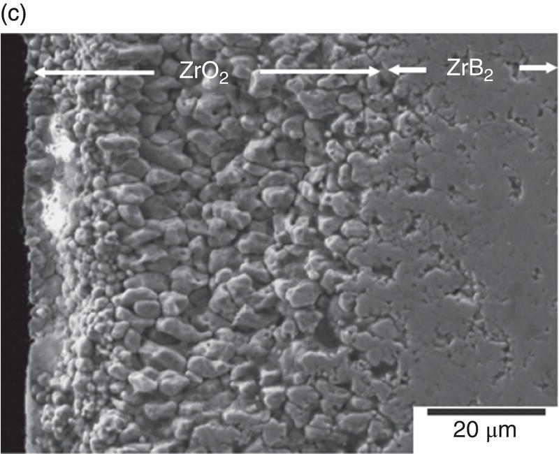
Figure 11.2. (a) Thermodynamic model for the oxidation of ZrB2 by Fahrenholtz [49] plotted in terms of phase stability regions for various stoichiometric compounds. (b) Observation by Talmy et al. of the decrease in retained boria in the scale with temperature shown replotted using data [50] and (c) microstructural cross section of ZrB2 after oxidation at 1500°C in air for 30 min, presented by Fahrenholtz [49].
The initial modeling effort on the pure diborides of Zr and Hf by Parthasarathy et al. was based on a schematic representation of the experimentally observed microstructural observations, as shown in Figure 11.3 [52]. The model assumed that the scale is made of two regions, an external glassy layer of liquid boria and an internal region consisting of two phases, a solid, but porous oxide of zirconia (or hafnia) with the pores filled with liquid boria. The model assumed that the solid oxide phase was impermeable to oxygen based on prior experimental observations of very low electronic conductivity, which would be required to ensure ambipolar diffusion where the transport of positively charged oxygen vacancies are accompanied by an appropriate (neutralizing) current of holes/electrons. The porous channels within the solid oxide were taken to be continuous and open such that oxygen can permeate through these channels to the substrate and oxidizes it. The oxygen permeation will be through a liquid of boria if the pores are filled, which happens at low temperatures. The molar ratio of boria to oxide formed from oxidation was taken to be proportional to the stoichiometry of the substrate diboride. Since the solid oxide was occupying most of the volume of the inner region, excess boria must be expelled as an external glassy layer (Fig. 11.3b). At the surface of this external boria layer, boria could evaporate by diffusion across a gaseous boundary layer whose width is determined by the flow conditions imposed. At intermediate temperatures, the evaporation of boria is sufficiently fast that no external layer forms. In fact, some boria from within the oxide pores evaporates leaving behind a partially porous oxide scale. Thus, in the intermediate temperature regime, oxygen permeates partially through these pores by gaseous diffusion or Knudsen diffusion and then through the remaining depth by permeation in liquid boria, as illustrated in Figure 11.3a. At very high temperatures, the boria is essentially lost by evaporation as rapidly as it forms (Fig. 11.3c). Using literature values for oxygen permeability and vapor pressures for boria, the model was able to capture oxidation data reported in the literature. In particular, the model predicted the temperatures of the transitions as shown in Figure 11.3d, in close agreement with experimental observations.
Figure 11.3. (a) A schematic of the microstructure interpreted from experimental data and used to build the oxidation model for ZrB2. The loss of boria was taken to be limited by diffusion through porous channels in the intermediate temperature regime. (b) At lower temperatures, an external liquid boria forms and remains stable. (c) At very high temperatures, the boria evaporates as fast as it can form leading to rapid oxidation. (d) The transition between the three regimes as a function of temperature as predicted by the model of Parthasarathy et al. [52].
A key complication in both measuring and predicting oxidation kinetics of the refractory diborides is the fact that the oxidation product, boria, is a glass with rapidly decreasing viscosity with increasing temperature. At temperatures of engineering interest, which are 1200–1600°C, the boria viscosity is sufficiently low to cause it to flow under gravity [54]. Thus, oxidized samples show significant variation in glass thickness depending on the orientation of the surface [23]. These effects were included in a modified version of the model for oxidation of diborides [51]. In this model, the effect of fluid flow was taken into account using a model adapted from models of water flooding from rainfall. As liquid boria forms by oxidation, it is added to the surface while gravitational forces tend to drain the glass in inverse proportion to its viscosity. The differential rate determines the actual thickness that is measured at the end of the experiment. This effect dominates in the low temperature regime where boria forms an external layer, but is not a factor once boria recedes into the porous oxide scale due to evaporation.
In the final iteration of the model for diboride oxidation kinetics, two more assumptions of the prior model were relaxed. First, inclusion of the effect of volume change associated with monoclinic to tetragonal phase change of the MeO2 phases is found to rationalize the observations by several investigators of abrupt changes in weight gain, recession, and oxygen consumed, as the temperature is raised through the phase transformation temperatures for ZrO2 and HfO2. Second, the inclusion of oxygen permeability in ZrO2 is found to rationalize the enhancement in oxidation behavior at very high temperatures (>1800°C) of ZrB2, while the effect of oxygen permeability in HfO2 is negligible. An important outcome of this model was that the pore fraction of the HfO2 and ZrO2 selected (0.03 and 0.04, respectively) to rationalize the data was very close to the volumetric shrinkage associated with the phase transformations of HfO2 and ZrO2 from monoclinic to tetragonal. Based on these considerations, the significant advantage of HfB2 over ZrB2 was credited to the higher transformation temperature and lower oxygen permeability of HfO2 compared with ZrO2. As shown in Figure 11.4, the model can rationalize the observed behavior both with respect to recession and with respect to oxygen consumed simultaneously. The inclusion of the effect of dopants (impurities) in ZrO2 or HfO2 can rationalize the enhanced oxidation rates seen at the highest temperatures. This arises from the enhanced electronic conductivity of the oxides by permitting ambipolar oxygen transport [52, 53, 55]. At the highest temperatures of the tests, it is possible that the oxide scales become contaminated by impurities from the furnace itself. Such observations have been made by Carney et al. and reported in recent work, where significant amount of calcium was found in samples oxidized at the highest temperatures [56]. Finally, the model included the effect of oxygen partial pressure through the dependence of permeability in glass and pores on the oxygen partial pressure and was able to rationalize the limited data available reasonably well, as shown in Figure 11.5.
Figure 11.4. The oxidation model of Parthasarathy et al. [53] was able to rationalize the sudden jumps in oxidation kinetics with temperature in the ZrB2 and HfB2 systems, by proposing that the volume change associated with phase transformation from monoclinic to tetragonal oxide (ZrO2 or HfO2) opens the porous channels in the scale. At the highest temperatures, the possible effect of unintentional dopant on the electronic conductivity of the oxide and thus the oxidation kinetics was estimated and was found to correlate with experimental data.
Figure 11.5. The proposed oxidation model [52] appears to capture the effect of oxygen partial pressure, but data in the literature are rather limited.
The model for pure diboride oxidation was later extended to include SiC-containing compositions [57]. In this work, once again, modeling started with recognition of the oxidation product morphology and chemistry as shown in Figure 11.6. Opila et al. first reported on the observation of a SiC-depleted zone beneath the substrate/oxide interface, during oxidation of ZrB2–SiC [20, 31]. This phenomenon was confirmed and rationalized using thermodynamic modeling by Fahrenholtz [48]. As shown in Figure 11.7, thermodynamic calculations provided justification for the formation of a depleted zone. The kinetic modeling by Parthasarathy et al. [57] started with a reduction of the reported microstructures to a schematic representation (Fig. 11.8) superimposed with reactions known from prior thermodynamic modeling by Fahrenholtz [48]. The key conclusion of Fahrenholtz was that the internal depletion zone was due to internal active oxidation of SiC to SiO. The extension of this required a transport mechanism that is able to transfer oxygen fast enough to cause SiC oxidation faster than the oxidation rate of ZrB2. This was achieved in the work of Parthasarathy et al. [57] by proposing a CO/CO2 countercurrent mechanism, as had been derived earlier by Holcomb and St. Pierre [58]. The rest of the modeling involved including the effect of silica on the viscosity and oxygen permeability of the glassy region. These values are available in the literature for pure boria and silica and some but not all intermediate compositions. The actual composition of borosilicate glass in the oxidation product is difficult to determine due to difficulties in measuring B content. The model assumed that the composition is the same as what might be predicted from stoichiometry of reactants and products and the volume fraction of the phases in the substrate. The viscosity and permeability for this composition was, in turn, estimated by assuming a logarithmic mean as the composition varied from pure boria to pure silica. With these assumptions, the model was able to capture the effect of SiC addition on the oxidation kinetics of ZrB2–SiC as shown in Figure 11.9. The model was also able to capture kinetics of oxidation of HfB2–SiC. The weight gain and scale thicknesses were captured well, except at the highest temperatures. The depletion zone thickness is predicted to be significant (>1 μm in 2.5 h) at temperatures above 1550°C. The experimentally observed depletion zone thicknesses are sometimes significantly larger than that predicted, implying an effect not yet captured by the model.
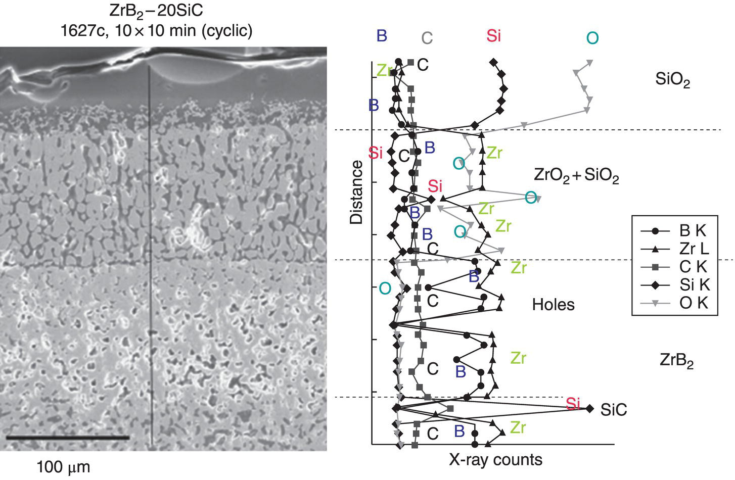
Figure 11.6. Microstructure and EDS mapping of the oxidation product of a 20 vol% SiC-containing ZrB2 sample showing the phases present along with morphology and a depleted zone lacking SiC in a matrix of ZrB2 after exposure in air at 1627°C for 100 min [20, 31].
Figure 11.7. Thermodynamic model for the oxidation of ZrB2–SiC calculated by Fahrenholtz [48] along with a schematic sketch showing a rationale for the formation of a depleted zone as observed by Opila et al. (Fig. 11.6).
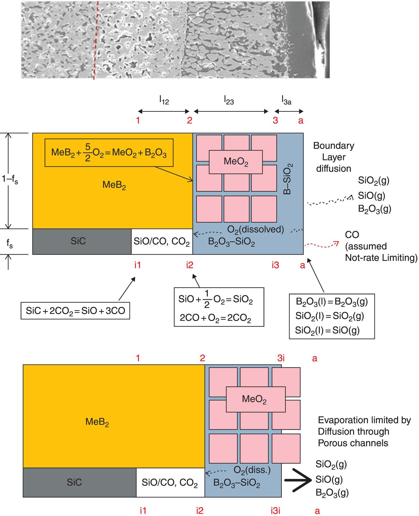
Figure 11.8. (a) Experimental observation of microstructural morphology (e.g., Fig. 11.6), (b, c) Schematics of the microstructural morphology and phase content of the oxidation product used in the model of Parthasarathy et al. [57].

Figure 11.9. Predicted variation in oxidation kinetics of SiC-containing ZrB2 as a function of SiC content compared with (a) experimental data of Talmy [66] and (b, c) Wang et al. [67]. Figure reproduced from the work of Parthasarathy et al. [57].
11.3 UHTC Behavior under Simulated Hypersonic Conditions
The application of UHTC compositions is at present focused on the cowl leading edge and fuel injection struts of scramjet engine for hypersonic flight. These two applications involve a unique geometry, thermal loading with large temperature gradients, very high fluid velocities with its associated mechanical vibrations, and aerodynamic and aerothermal loads. While a number of tests have evolved over the past several decades as mentioned in the introduction, this section focuses on a recent study that examined the use of a direct-connect scramjet engine as a wind tunnel to simulate conditions of free flight of leading-edge samples of a UHTC (HfB2–20 vol% SiC) composition.
The details of the purpose, design, construction, and evaluation of the direct-connect scramjet engine have been described by Gruber et al. [38, 59, 60]. A brief description is given here. Ambient air is compressed before being expanded through an isolator nozzle resulting in a supersonic flow at Mach 1.8–2. The cooling that results from the expansion is augmented by adding heat using a combustion heater. Oxygen lost during combustion heating is compensated by adding oxygen to ensure the correct partial pressure of oxygen in the resulting fluid that enters the supersonic combustor. The postcombustion section employs an exit nozzle before reaching a probe housing. It is within the probe housing that leading-edge samples were introduced. The gas composition at this location varies with combustor section but typically includes 5–10% moisture with a total static pressure near 1 atm. Samples were mounted on a sample holder, constructed of water-cooled thermal barrier-coated Inconel [39, 40]. The samples were visible during the run through quartz windows. The scramjet rig was fully calibrated, and important parameters including enthalpy, total temperatures, gas flow velocities, gas composition, and pressures were available as a function of time during the run. The fluid flow parameters such as velocity (U) and static pressure (p1), along with static temperature (T1) and specific heat ratio of the gas composition (γ), were used to calculate the heat flux (Qw) experienced by the leading-edge samples [7, 10]:
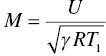
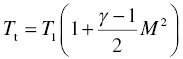
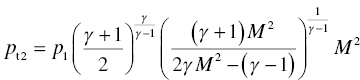

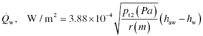
In the above set of equations, M is the Mach number, Tt is the total temperature, Twall is the material surface temperature, pt2 is the total pressure behind the bow shock, r is the radius of curvature of the leading edge, Cp is the specific heat of fluid, haw is the total enthalpy of the fluid (=CpTt), the hw is the enthalpy of the fluid at the material wall temperature (=CpTwall). The heat flux varies with orientation of the material wall as well as distance from the bow shock. These variations are given by the following:
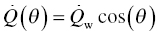
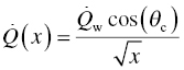
where θ gives the angle between the direction of fluid flow and the normal to the wall surface ( =0 at the tip of the leading edge) and x is the distance from the tip of the leading edge. θc and Qw refer to the orientation and the heat flux at the tangential point where the cylindrical surface of the tip meets the slant face of the leading-edge wedge. It must be noted that while the Equations 11.6 and 11.7 capture the dependences accurately, they are approximations to the actual variation of the heat flux. Further note that the net heat flux at any location is a function of the wall temperature and, thus, will vary with time. The steady-state material temperature will depend on radiation heat flux back to the atmosphere and thermal conduction within the solid. The wall temperature will depend on the static temperature of the fluid and material thermal properties. Thus, a thermal model that includes the aerothermal heating, radiation, and conduction for a given geometry is required. Using such a model, the thermal profiles were calculated for a large (50.8 × 50.8 mm) leading-edge sample under free flight and compared to the thermal response of a smaller (12.7 × 12.7 mm) leading-edge sample used in the scramjet rig [40]. The results from these calculations are shown in Figure 11.10. An important outcome of the thermal model was that the thermal properties of the material significantly affect the temperature gradient. Materials based on diboride UHTCs have higher thermal conductivities at high temperatures than other ceramics including SiC, potentially making them better material candidates for these applications.
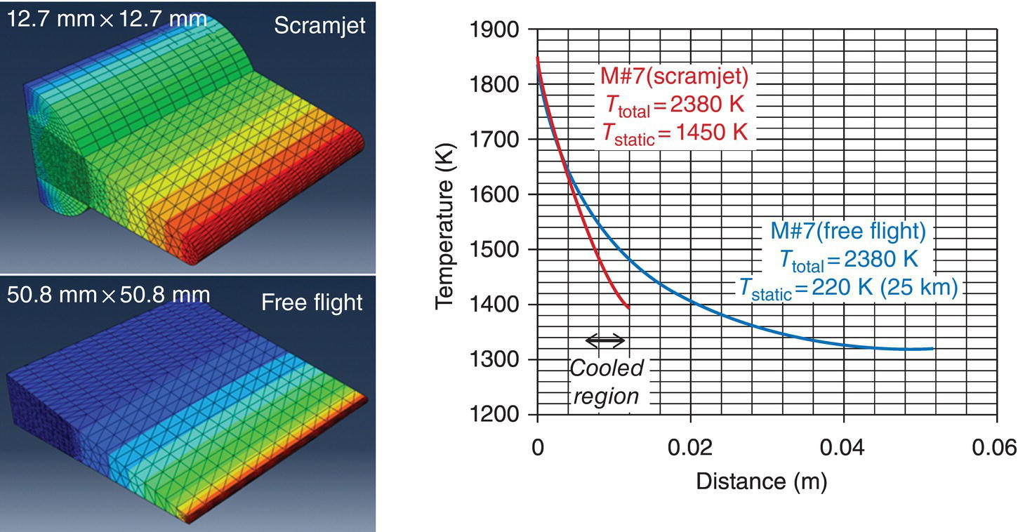
Figure 11.10. Thermal model of a leading-edge sample of UHTC was compared for two cases, one for the sample used in the scramjet tests and another simulating free flight. The results showed that the thermal profiles are nearly the same for the two cases near the leading-edge tip, which were of experimental interest [40].
Figure 11.11 shows a typical oxidation scale formed on a UHTC (HfB2–20 vol% SiC) leading-edge sample after exposure in the scramjet. The microstructural characterization of the UHTC showed that the scale was different than what is normally observed in samples after furnace oxidation. First, the external glassy layer is absent. Second, no depletion layer was observed. Third, silica was absent in the outer regions of the hafnium-rich oxide scale. Fourth, the formation of hafnon (HfSiO4) was observed in the outer regions. While the reasons for these differences are not clear, it is suspected that the high flow rate of the environment along with the presence of moisture in the atmosphere may be responsible for these differences.
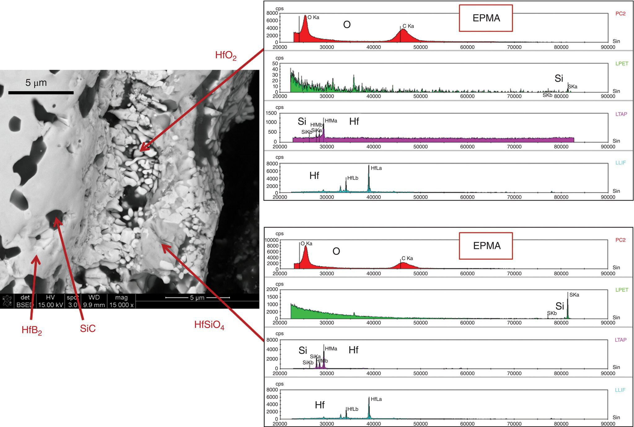
Figure 11.11. The oxidation scale formed on the UHTC sample tested in the scramjet under conditions representing free flight Mach numbers of 6.2–7. No external glassy layer or depleted zone was observed; however, hafnon (HfSiO4) was present in the oxide scale as evidenced by both X-ray diffraction and EPMA analysis shown here [40].
11.4 Comparing Model Predictions to Leading-Edge Behavior
The modeling work by Parthasarathy et al. [57] included the effect of fluid flow on the evaporation rates of boria and silica. Thus, the model was considered sufficient for predicting behavior of leading edges exposed to simulated hypersonic conditions. The model, however, did not include the physical shear mechanism by which the external glassy layer could be thinned down. Under most conditions of tests, evaporation rates were high enough to result in little or no external glassy layer; thus, shear forces were irrelevant. The thermal model described in the earlier section was used to obtain the thermal profile (time vs. temperature) at the tip of the leading edge and fed into the oxidation model to predict the oxidation scale thickness, depletion thickness, and recession. The aerothermal calculations were used to obtain the total pressure and fluid velocity behind the bow shock and used for the model predictions. The results obtained showed that predicted oxide thicknesses were close to the experimental results, although they were consistently lower. Impurities and moisture in the environment could have altered the oxygen permeation across the scales. The formation of hafnon could have increased the volume fraction of the porous channels. Finally, the possibility of glassy material being drawn out of the porous channels by the high velocity fluid flow was suggested.
Based on the reasonable predictions presented above, the model was used to estimate the behavior of a UHTC leading-edge behavior under hypersonic free flight conditions. Figure 11.12 summarizes the predictions. The results are shown as a function of free flight Mach numbers. The leading-edge tip temperatures, steady-state heat flux, thermal gradients in the sample, and oxidation thickness with time are shown. It must be noted that the results are sensitive to the thermal conductivity and specific heat of the composition used. A significant variation in thermal properties of UHTCs with processing method has been noted by several groups [32]. For example, the use of SiC results in higher tip temperatures due to the lower thermal conductivity at high temperatures, when compared with nominally pure UHTCs.

Figure 11.12. The thermal model for the leading edge (made of HfB2–20 vol% SiC) under hypersonic flight conditions when combined with oxidation models can predict parameters of interest for design. The temperature at the tip of the leading edge is lower than the total temperature often assumed. Similarly, the steady-state heat flux is lower than the cold wall heat flux. The thermal profiles show a steep drop in temperature away from the tip, and the oxidation rates appear to be tolerable for UHTCs at Mach 6.5 [40].
In closing, the following limitations are worth pointing out with a view to direct future work. Oxidation modeling of UHTCs includes some assumptions that are discussed in the following. First, the refractory oxide, ZrO2 or HfO2, is assumed to be impermeable to oxygen due to low electronic conductivity. This is a good approximation if the oxide is pure, but impurities can enhance the conductivity significantly especially at high temperatures (>2000 K). Impurities may be present in the raw materials or may be acquired during testing or use. Second, the variation of boria content with distance in the scale has been approximated, and boria content can significantly affect viscosity and oxygen permeation in borosilicate glasses. Third, the effect of mechanical shear on the external glassy layer has been ignored.
The scramjet rig offers a unique approach to evaluate leading-edge candidate materials using simulated hypersonic conditions but has some limitations. First, the gas chemistry is not that of ambient air. The gas contains a significant amount of water and carbon dioxide (about 10% each). In addition, impurities from the components of the rig cannot be easily avoided. The use of water as coolant for parts of the rig interfered with observation as it collected in the recess of the window; however, future design changes could alleviate this. The glass windows currently in use prevented the use of optical pyrometry. The use of a suitable material such as ZnSe for the window will alleviate this difficulty provided the material is stable at the temperatures of the rig walls. The actual velocity of the gases is not hypersonic even though the heat content of the gases simulates hypersonic flight conditions. The rig used in the reported work is limited to a maximum of Mach 7. Finally, the scramjet rig is a unique facility available only to a very limited group of researchers and only at periodic intervals. However, if the community recognizes it to be a useful method, a dedicated rig might be constructed that is smaller in scale, but it will be expensive.
11.5 Behavior of UHTCs under Other Test Methods
Various compositions of UHTCs are being studied by different investigators to explore the possibility of enhancing the environmental degradation resistance at high temperatures. The evaluations have largely been based on furnace oxidation tests due to the ease and low cost of the test method. It is appropriate for initial screening of compositions and for understanding mechanisms of oxidation in static laboratory air; however, using these data to predict performance under hypersonic flight conditions is not trivial. Using a mechanistic model that captures the furnace data in combination with scramjet exposure tests shows promise. In the literature, one can find several other approaches that have been pursued to evaluate performance of candidate materials for thermal protection under hypersonic flight conditions. The merits and demerits of these approaches are discussed briefly in the following.
11.5.1 Arcjet Test
The arcjet test is a widely accepted method for evaluating performance of materials under reentry conditions, developed and used widely by NASA to design space vehicles. It uses a plasma-generated gas mixture, which contains a high fraction of ionized atoms of oxygen and nitrogen. Recombination of the charged species is catalyzed by the sample surface to release heat. The plasma is accelerated to high velocities (supersonic but not hypersonic) using an electric field before it is directed onto the sample. The enthalpy of the gases per unit area of the sample is reported as well as the surface temperature of the sample, which is measured using an optical pyrometer. The key advantage of this method is that it provides a simulation of dissociation of air that occurs behind the bow shock at hypersonic speeds. The catalytic coefficient for recombination varies with sample composition and can also change during the test since the surface composition changes as the sample oxidizes complicating interpretation and modeling of test results. Until recently, the test has used mostly flat samples or large-radius conical samples, and thus, the effect of a sharp leading-edge geometry had not yet been captured. Recent works are beginning to study samples with sharp geometries, but the aerothermal heat flux distribution during free flight is not reproduced in these tests [61–63]. The test is also not best for evaluating materials for hypersonic speeds in the range of Mach 5–7, where very little dissociation of gases is expected. Finally, the very high cost of the test makes it prohibitive for most studies.
11.5.2 Laser Test
The availability of laser facilities at reasonable cost compared to arcjets has resulted in tests that evaluate UHTC compositions using lasers as the heat source. These tests use a prescribed heat flux, calibrated using optical standards, on a flat geometry of the sample for a predetermined length of time. In some cases, an external tangential flow of air typically at subsonic speeds is included. The advantage of this method is that it requires a short setup and run time and several samples can be tested within a short period of time. The ambient fluid composition is nearly exact as its air and material surface temperature can be monitored accurately during the test using optical pyrometry. The key disadvantage of the method is that the actual heat flux absorbed by the sample varies with composition, wavelength of the laser, and temperature of the sample. Thus, laser absorptance and emittance of each sample must be measured as a function of temperature and accounted for when interpreting the results. Very few studies report these properties of UHTCs, with most studies assuming the absorptance to be unity. Emissivity has been reported in some recent work, but factors such as machining method can influence emissivity [64, 65]. The laser method also uses a constant heat flux, whereas in real flight heat flux varies from nearly the cold wall heat flux to the steady-state heat flux gradually as the sample heats. The steady-state heat flux will be affected by the emissivity of the material and ambient temperature during flight; this is not captured in the laser test.
11.5.3 Oxyacetylene Torch Test
The oxyacetylene torch has long been used as a heat source and has recently been revived as a low-cost alternative to arcjet and laser tests. In this test, a flat sample is exposed to hot combustion gases of an oxyacetylene torch by holding the sample at a calibrated distance from the torch tip. The calibration is usually made based on the measured optical pyrometer reading on the hottest section of the exposed sample. The heat flux is usually not measured or reported. The advantages of this method are that it provides high heat fluxes, is very quick and inexpensive, and, as such, can be used as a good oxidation screening tool for the relative comparison of material compositional variations. The disadvantage is the lack of standardization of the test procedure and lack of calibration with respect to heat flux. The exact composition of the combustion product is also unknown and depends on the initial oxygen–acetylene ratio, as well as on location within the flame. Water is present as a major product of combustion, which can complicate interpretation of the results.
11.6 Summary
The status of mechanistic understanding of the degradation of UHTC leading-edge components under hypersonic flight conditions was reviewed. The oxidation behavior studied under conventional methods and reported over the past several decades could be interpreted reasonably well using analytical models that assume the glassy regions as the only pathway for oxygen permeation. Extension of this model to hypersonic flow conditions shows promise, but more experimental and modeling work is required to develop a comprehensive understanding. UHTC-based leading-edge samples appear to withstand the simulated hypersonic conditions up to Mach 7. However, UHTCs are found to degrade much more rapidly under arcjet conditions. The behavior under arcjet appears to be unique and different from other test methods and thus the least understood.
References
- 1. Jackson TA, Eklund DR, Fink AJ. High speed propulsion: performance advantage of advanced materials. J Mater Sci 2004;39:5905–5913.
- 2. Voland RT, Huebner LD, McClinton CR. X-43A hypersonic vehicle technology development. Acta Astronaut 2006;59:181–191.
- 3. Cook S, Hueter U. NASA's integrated space transportation plan—3rd generation reusable launch vehicle technology update. Acta Astronaut 2003;53:719–728.
- 4. Norris G. High-speed strike weapon to build on X-51 flight. Aviation Week & Space Technology; May 20, 2013.
- 5. McClinton CR, Rausch VL, Shaw RJ, Metha U, Naftel C. Hyper-X: foundation for future hypersonic launch vehicles. Acta Astronaut 2005;57:614–622.
- 6. Kerans RJ. Concurrent material and structural design with innovative ceramic composites, Final Report for DARPA/DSO [AFRL Technical Report AFRL-ML-WP-TR-2006-4130] WPAFB, OH: Air Force Research Laboratory; 2005.
- 7. Ames Research Staff. Equations, tables and charts for compressible flow. National Advisory Committee for Aeronautics [Report 1135]. Washington, DC: NASA HQ; 1953.
- 8. Lees L. On the boundary layer equations in hypersonic flow and their approximate solutions. J Aero Sci 1953;20 (2):143–145.
- 9. Fay JA, Riddell FR. Theory of stagnation point heat transfer in dissociated air. J Aero Sci 1958;25:73–85.
- 10. Zoby EV. Empirical stagnation-point heat-transfer relation in several gas mixtures at high enthalpy levels. NASA tech note, NASA TN D-4799. Washington, DC: NASA HQ; 1968.
- 11. Scala SM, Gilbert LM. Theory of hypersonic laminar stagnation region heat transfer in dissociating gases. NASA tech note NAS 7-100 Accession No. N71-70918. Washington, DC: NASA HQ; 1963.
- 12. NASA. U. S. standard atmosphere. NOAA document ST 76-1562. Washington, DC: NASA HQ; 1976.
- 13. Clougherty EV, Pober RL, Kaufman L. Synthesis of oxidation resistant metal diboride composites. Trans Met Soc AIME 1968;242:1077–1082.
- 14. Kaufman L, Clougherty E. Technical Report RTD-TDR-63-4096: part 1. WPAFB, OH: Air Force Research Laboratory; December 1963.
- 15. Kaufman L, Clougherty E. Investigation of boride compounds for very high temperature applications. Technical Report RTD-TDR-63-4096: part 2. WPAFB, OH: Air Force Research Laboratory; February 1965.
- 16. Kaufman L, Clougherty EV, Berkowitz-Mattuck JB. Oxidation characteristics of hafnium and zirconium diboride. Trans Metall Soc AIME 1967;239:458–466.
- 17. Kaufman L, Nesor H. Stability characterization of refractory materials under high velocity atmospheric flight conditions, part III, vol. III: experimental results of high velocity hot gas/cold wall tests, AFML-TR-69–84; 1970.
- 18. Opeka MM, Talmy IG, Zaykoski JA. Oxidation-based materials selection for 2000°C+ hypersonic aerosurfaces: theoretical considerations and historical experience. J Mater Sci 2004;39:5887–5904.
- 19. Montverde F, Savino R, Fumo M. Dynamic oxidation of ultra-high temperature ZrB2–SiC under high enthalpy supersonic flows. Corros Sci 2011;53:922–929.
- 20. Levine SR, Opila EJ, Halbig MC, Kiser JD, Singh M, Salem JA. Evaluation of ultra-high temperature ceramics for aeropropulsion use. J Eur Ceram Soc 2002;22:2757–2767.
- 21. Marschall J, Pejakovic DA, Fahrenholtz WG, Hilmas GE, Zhu S, Ridge J, Fletcher DG, Asma CO, Thomel J. Oxidation of ZrB2–SiC ultrahigh-temperature ceramic composites in dissociated air. J Thermophys Heat Transfer 2009;23 (2):267–278.
- 22. Tripp WC, Graham HC. Thermogravimetric study of the oxidation of ZrB2 in the temperature range of 800 to 1500°C. J Electrochem Soc 1971;118 (7):1195–1199.
- 23. Carney CM, Mogilevsky P, Parthasarathy TA. Oxidation behavior of zirconium diboride silicon carbide produced by the spark plasma sintering method. J Am Ceram Soc 2009;92 (9):2046–2052.
- 24. Carney CM. Oxidation resistance of hafnium diboride-silicon carbide from 1400–2000°C. J Mater Sci 2009;44:5673–5681.
- 25. Carney CM, Parthasarathy TA, Cinibulk MK. Oxidation resistance of hafnium diboride ceramics with additions of silicon carbide and tungsten boride or tungsten carbide. J Am Ceram Soc 2011;94 (8):2600–2607.
- 26. Opeka MM, Talmy IG, Wuchina EJ, Zaykoski JA, Causey SJ. Mechanical, thermal and oxidation properties of refractory hafnium and zirconium compounds. J Eur Ceram Soc 1999;19:2405–2414.
- 27. Meng S, Chen H, Hu J, Wang Z. Radiative properties characterization of ZrB2–SiC-based ultrahigh temperature ceramic at high temperature. Mater Design 2011;32:377–381.
- 28. Zhang X-H, Hu P, Han J-C. Structure evolution of ZrB2–SiC during the oxidation in air. J Mater Res 2008;23 (7):1961–1972.
- 29. Han W-B, Hu P, Zhang X-H, Han J-C, Meng S-H. High-temperature oxidation at 1900°C of ZrB2–xSiC ultrahigh-temperature ceramic composites. J Am Ceram Soc 2008;91 (10):3328–3334.
- 30. Opila E, Levine S, Lorincz J. Oxidation of ZrB2- and HfB2-based ultra-high temperature ceramics: effect of Ta additions. J Mater Sci 2004;39:5969–5977.
- 31. Opila EJ, Halbig MC. Oxidation of ZrB2–SiC. Ceram Eng Sci Proc 2001;22 (3):221–228.
- 32. Gasch M, Johnson S. Physical characterization and arcjet oxidation of hafnium-based ultra high temperature ceramics fabricated by hot pressing and field-assisted sintering. J Eur Ceram Soc 2010;30:2337–2344.
- 33. Savino R, Fumo MDS, Paterna D, Maso AD, Monteverde F. Arc-jet testing of ultra-high-temperature-ceramics. Aerosp Sci Technol 2010;14:178–187.
- 34. Jayaseelan DD, Jackson H, Eakins E, Brown P, Lee WE. Laser modified microstructures in ZrB2, ZrB2/SiC and ZrC. J Eur Ceram Soc 2010;30 (11):2279–2288.
- 35. Karlsdottir SN, Halloran JW. Oxidation of ZrB2–SiC: influence of SiC content on solid and liquid oxide phase formation. J Am Ceram Soc 2009;92 (2):481–486.
- 36. Gangireddy S, Karlsdottir SN, Halloran JW. High-temperature oxidation at 1900°C of ZrB2–xSiC ultrahigh-temperature ceramic composites. Key Eng Mater 2010;434–435:144–148.
- 37. Paul A, Jayaseelan DD, Venugopal S, Zapata-Solvas E, Binner J, Vaidhyanathan B, Heaton A, Brown P, Lee WE. UHTC composites for hypersonic applications. Bull Am Ceram Soc 2012;91 (1):1–8.
- 38. Gruber M, Donbar J, Jackson KJ, Mathur T, Baurle R, Eklund D, Smith C. Newly developed direct-connect high-enthalpy supersonic combustion research facility. J Propul Power 2001;17 (6):1296–1304.
- 39. Parthasarathy TA, Petry MD, Jefferson G, Cinibulk MK, Mathur T, Gruber MR. Development of a test to evaluate aerothermal response of materials to hypersonic flow using a scramjetwind tunnel. Int J Appl Ceram Tech 2011;8 (4):832–847.
- 40. Parthasarathy TA, Petry MD, Cinibulk MK, Mathur T, Gruber MR. Thermal and oxidation response of UHTC leading edge samples exposed to simulated hypersonic flight conditions. J Am Ceram Soc 2013;96 (3):907–915.
- 41. Wagner C. Theoretical analysis of the diffusion processes determining the oxidation rate of alloys. J Electrochem Soc 1952;99 (10):369–380.
- 42. Wagner C. Passivity and inhibition during the oxidation of metals at elevated temperatures. Corros Sci 1965;5:751–764.
- 43. Fenter JR. Refractory diborides as engineering materials. SAMPE Q 1971;2 (3):1–15.
- 44. Hill ML. Materials for small radius leading edges for hypersonic vehicles, AIAA/ASME Conference on Structures, Structural Dynamics and Materials; Palm Springs, CA, March 29-3 1967.
- 45. Monteverde F, Bellosi A. Oxidation of ZrB2-based ceramics in dry air. J Electrochem Soc 2003;150 (11):B552–B559.
- 46. Fahrenholtz WG, Hilmas GE, Chamberlain AL, Zimmermann JW. Processing and characterization of ZrB2-based ultra-high temperature monolithic and fibrous monolithic ceramics. J Mater Sci 2004;39 (19):5951–5957.
- 47. Wuchina E, Opeka M, Causey S, Buesking K, Spain J, Cull A, Routbort J, Guitierrez-Mora F. Designing for ultrahigh-temperature applications: the mechanical and thermal properties of HfB2, HfCx, HfNx and a-Hf(N). J Mater Sci 2004;39:5939–5949.
- 48. Fahrenholtz WG. Thermodynamic analysis of ZrB2–SiC oxidation: formation of a SiC-depleted region. J Am Ceram Soc 2007;90 (1):143–148.
- 49. Fahrenholtz WG. The ZrB2 volatility diagram. J Am Ceram Soc 2005;88 (12):3509–3512.
- 50. Talmy IG, Zaykoski JA, Opeka MA. Properties of ceramics in the ZrB2/ZrC/SiC system prepared by reactive processing. Ceram Eng Sci Proc 1998;19 (3):105–112.
- 51. Parthasarathy TA, Rapp RA, Opeka M, Kerans RJ. A model for transitions in oxidation regimes of ZrB2. Mater Sci Forum 2008;595–598:823–832.
- 52. Parthasarathy TA, Rapp RA, Opeka M, Kerans RJ. A model for the oxidation of ZrB2, HfB2 and TiB2. Acta Mater 2007;55:5999–6010.
- 53. Parthasarathy TA, Rapp RA, Opeka M, Kerans RJ. Effect of Phase change and oxygen permeability in oxide scales on oxidation kinetics of ZrB2 and HfB2. J Am Ceram Soc 2009;92 (5):1079–1086.
- 54. Eppler RA. Viscosity of molten B2O3. J Am Ceram Soc 1966;49 (12):679–680.
- 55. Patterson JW. Conduction domains for solid electrolytes. J Electrochem Soc 1971;118:1033–1039.
- 56. Carney CM, Parthasarathy TA, Cinibulk MK. Separating test artifacts from material behavior in the oxidation studies of HfB2–SiC at 2000°C and above. Int J Appl Ceram Technol 2013;10 (2).
- 57. Parthasarathy TA, Rapp RA, Opeka M, Cinibulk MK. Modeling oxidation kinetics of SiC-containing refractory diborides. J Am CeramSoc 2012;95 (1):338–349.
- 58. Holcomb GR, St.Pierre GR. Application of a counter-current gaseous diffusion model to the oxidation of Hafnium carbide at 1200°C to 1530°C. Oxid Met 1993;40 (1/2):109–118.
- 59. Mathur T, Gruber M, Jackson K, Donbar J, Donaldson W, Jackson T, Billig F. Supersonic combustion experiments with a cavity-based fuel injector. J. Propul Power 2001;17 (6):1305–1312.
- 60. Gruber M, Smith S, Mathur T. Experimental characterization of hydrocarbon-fueled axisymmetric scramjet combustor flowpaths. AIAA Paper 2011–2311; 2011.
- 61. Scatteia L, Alfano D, Cantoni S, Monteverde F, Fumo MDS, Maso AD. Plasma torch test of an ultra-high-temperature ceramics nose cone demonstrator. J Spacecraft Rockets 2010;47:271–279.
- 62. Gardi R, Vecchio AD, Marino G, Russo G. CIRA activities on UHTC's: on-ground and in flight experimentations. Proceedings of the 17th AIAA International Space Planes and Hypersonic Systems and Technologies, Paper 2011-2303; San Francisco, CA, April 11–14, 2011.
- 63. Monteverde F, Alfano D, Savino R. Effects of LaB6 addition on arc-jet convectively heated SiC-containing ZrB2-based ultra-high temperature ceramics in high enthalpy supersonic air-flows. Corros Sci 2013;75:443–453.
- 64. Scatteia L, Alfano D, Monteverde F, Sans J-L, Balat-Pichelin M. Effect of the machining method on the catalycity and emissivity of ZrB2 and ZrB2–HfB2-based ceramics. J Am Ceram Soc 2008;91:1461–1468.
- 65. Scatteia L, Borrelli R, Cosentino G, Beche E, Sans J-L, Balat-Pichelin M. Catalytic and radiative behaviors of ZrB2–SiC ultrahigh temperature ceramic composites. J Spacecraft Rockets 2006;43:1004–1012.
- 66. Talmy I. Effect of SiC content on oxidation kinetics of SiC-ZrB2, Unpublished work. Naval Surface Warfare Center: Carderock (MD); 2005.
- 67. Wang M, Wang C-A, Yu L, Huang Y, Zhang Z. Oxidation behavior of SiC platelet-reinforced ZrB2 ceramic matrix composites. Int J App Ceram Tech 2012;9 (1):178–185.