15
Nuclear Applications for Ultra-High Temperature Ceramics and MAX Phases
William E. Lee1, Edoardo Giorgi1, Robert Harrison1, Alexandre Maître2, and Olivier Rapaud2
1 Centre for Advanced Structural Ceramics, Department of Materials, Imperial College London, London, UK
2 Centre Européen de la Céramique, University of Limoges, Limoges Cedex, France
This chapter begins with a brief presentation of future nuclear reactors. Next, current uses of ceramics in the nuclear industry are reviewed, which, with the exception of graphite moderators and B4C control rods, rely largely on oxides or silicates. Then, the potential for using non-oxide Ultra-High Temperature Ceramics (UHTCs) and MAX phases1 in future (so-called Generation IV) fission and fusion reactors is discussed.
15.1 Future Nuclear Reactors
The feasibility and performance capabilities of next generation nuclear energy systems have been established via the Generation IV International Forum (GIF). GIF, which is a cooperative international endeavor, has identified four main nuclear energy systems that employ a variety of reactor, energy conversion, and fuel cycle technologies. It had to allow sustainable development of the nuclear sector [1], to increase its economic competitiveness and to reinforce the reliability and safety of future nuclear reactors. These concepts are described in detail in this section.
The Very high temperature reactor (VHTR) concept is a graphite-moderated reactor with a once-through uranium fuel cycle. The VHTR is a type of High-Temperature Reactor (HTR) that can conceptually have an outlet temperature of 1000°C. The reactor core can be either a “prismatic block” or a “pebble-bed” core. The high temperatures enable applications such as process heat or hydrogen production via the thermochemical sulfur–iodine cycle. Helium is the coolant because it is an inert gas, so it will generally not chemically react with any nuclear fuel or cladding material. Additionally, exposing helium to neutron radiation does not make it radioactive, unlike most other possible coolants. Super Critical Water Reactors (SCWRs) are one of the three types of Light Water Reactor (LWR), the other types being Boiling Water Reactors (BWRs) and Pressurized Water Reactors (PWRs). A SCWR usually operates at higher pressure and temperature, with a direct once-through cycle like a BWR, and the water is always in a single, liquid state as in the PWR. The SCWR is a promising advanced nuclear system because of its high thermal efficiency (~45% vs. ~33% for current LWRs) and simple design. A Molten Salt Reactor (MSR) is a class of nuclear fission reactor in which the primary coolant, or even the fuel itself, is a molten salt mixture. MSRs run at higher temperatures than water-cooled reactors for higher thermodynamic efficiency, while staying at low vapor pressure. In many designs, the nuclear fuel is dissolved in the molten fluoride salt coolant as uranium tetrafluoride (UF4). The fluid becomes critical in a graphite core, which serves as the moderator. Solid fuel designs rely on ceramic fuel dispersed in a graphite matrix, with the molten salt providing low-pressure, high-temperature cooling.
Fast Neutron Reactors (FNRs) are a technological step beyond conventional power reactors. They offer the prospect of vastly more efficient use of uranium resources and the ability to burn actinides, which are otherwise the long-lived component of high-level nuclear wastes. The fast reactor has no moderator and relies on fast neutrons alone to cause fission, which for uranium is less efficient than using slow neutrons. Hence, a fast reactor usually uses plutonium as its basic fuel, since it fissions sufficiently with fast neutrons to sustain the reaction. The coolant is a liquid metal (normally sodium or lead for future reactors) or gas (helium) to avoid any neutron moderation and provide a very efficient heat transfer medium.
In this class, the Gas-cooled Fast Reactor (GFR) (i.e., FNR using helium as coolant) is a nuclear reactor design that is currently under development. It features a fast-neutron spectrum and closed fuel cycle for efficient conversion of fertile uranium and management of actinides. The reference reactor design is a helium-cooled system operating with an outlet temperature of 850°C. Several fuel forms are being considered for their potential to operate at very high temperatures and to ensure retention of fission products (FP): composite ceramic fuel, advanced fuel particles, or ceramic clad elements of actinide compounds.
The International Thermonuclear Experimental Reactor (ITER) program is the next step in studying the fusion reaction, which will be achieved in a tokamak device. Tokamaks use magnetic fields to contain and control the hot plasma in which the fusion reactions occur. The fusion between deuterium and tritium will produce one helium nuclei, one neutron, and energy. The helium nucleus carries an electric charge, which will respond to the magnetic fields of the tokamak and remain confined within the plasma. However, some 80% of the energy produced is carried away from the plasma by the neutron that has no electrical charge and is, therefore, unaffected by magnetic fields. The neutrons will be absorbed by the surrounding walls of the tokamak, transferring their energy to the walls as heat. Consequently, the wall materials will be submitted to extreme working conditions with the temperature reaching 1300°C (under normal conditions) and the fast neutron energy being 14 MeV.
Nuclear fuel and cladding materials that are of interest in these different nuclear reactor concepts are given in Table 15.1 which also summarizes the usual reactor working conditions and the corresponding nuclear fuel materials.
Table 15.1. The GIF reactor designs
| Acronym | Coolant | Neutron energy | Temperature (°C) | Fuel design | Cladding/structural materials |
| GFR | Helium | Fast | 850 | (U, Pu)C (+liner) | SiC |
| LFR | Pb-Bi or Pb | Fast | 480–800 | Metal alloy or nitride | Ferritic steel or ceramic (SiC, ZrN) |
| MSR | Molten fluoride salt | Fast/thermal | 700–800 | Th-U or U-Pu | Ni-based alloys |
| SFR | Liquid sodium | Fast | 550 | (U, Pu)O2 + MA/Na in gap | Ferritic or ODS |
| U-Pu-MA-Zr metal alloy | |||||
| SCWR | Supercritical water | Thermal/fast | 510–625 | UO2 | Austenitic, ferritic-martensitic stainless steel, Ni-alloy cladding |
| VHTR | Helium | Thermal | 900–1000 | TRISO UO2(+UC) | Graphite prismatic-type, graphite pebbles |
LFR, Lead-cooled Fast Reactor; ODS, Oxide-Dispersion Strengthened ferritic stainless steels; SFR, Sodium-cooled Fast Reactor; TRISO, TRistructural ISOtropic.
15.2 Current Nuclear Ceramics
Ceramics have properties that make them particularly useful to the nuclear industry, where they are currently used predominantly as fuels and waste forms [2]. They may contain fissionable species and have sufficient thermal conductivity, refractoriness, phase stability, and radiation resistance in fuels. In waste forms, they have the ability to accommodate radionuclides and other waste species, are relatively easy to process, and are durable including against radiation damage. Table 15.2 lists some current nuclear ceramics and their key properties.
Table 15.2. Typical properties of some current nuclear ceramics
| Ceramic properties | UO2 | PuO2 | (U0.8Pu0.2)O2 | Boro-silicate glass | Synroc |
| Theoretical density (g/cm3) | 10.96 [3] | 11.44 [4] | 11.04 | 2.23 [5] | 4.35 [5] |
| Melting point (°C) | 3120 ± 20 [4] | 2674 ± 20 [4] | 3256 | 1100 [6] | 1370 [6] |
| Thermal conductivity (W/m·K) | |||||
| 1273°C | 2.9 [7] | 2.6 [6] | 2.6 | 1.0 (RT) [6] | 3.0 (RT) [6] |
| 2273°C | 1.8 [7] | 2.4 | |||
| Crystal structure | Fluorite | Fluorite | Fluorite | — | Hollandite-zirconolite-perovskite |
| Handling | In air | In air | In air | In air | In air |
| Processing capability | Demonstrated on industrial scale for aqueous and pilot scale for pyro-processes | Demonstrated on industrial scale for aqueous and pilot scale for pyro-processes | Demonstrated on industrial scale for aqueous and pilot scale for pyro-processes | Decades of industrial | Demonstrated on pilot scale |
| Fabrication/irradiation experience | Large | Moderate/high | Large | Large | Moderate/high |
Uranium dioxide ceramic is the main fuel used in nuclear reactors. UO2 is highly stable, the high symmetry fluorite structure demonstrating good corrosion resistance to water and steam making the fuel pellets free from anisotropic effects, with no phase transformations occurring up to a melting point of 2865°C. Fluorite structured UO2 (space group Fm3¯ m) exhibits a broad range of stoichiometry (UO2±x) facilitated by oxygen defects (vacancies or interstitials), where the O/U ratio can reach 1.7 at approximately 2700 K on the oxygen-deficit side and over 2.2 by approximately 2000 K on the oxygen-excess side (see Fig. 15.1).
Figure 15.1. Phase diagram of the uranium–oxygen system.
Reproduced from Guéneau et al. [8].
The major disadvantage of uranium dioxide as a fuel is its poor thermal conductivity (Table 15.2), which is exacerbated by the presence of oxygen defects. Due to the low thermal conductivity of UO2, the interior of the pellets may reach much higher temperatures during reactor operation than the edges (center line temperatures are often 1100°C, while a few millimeters away at the edge of the pellet, the temperature will be approximately 380°C). To try to account for this, pellets are “dished” at each end to accommodate the increased thermal expansion of the pellet interior relative to that of the edges (Fig. 15.2).
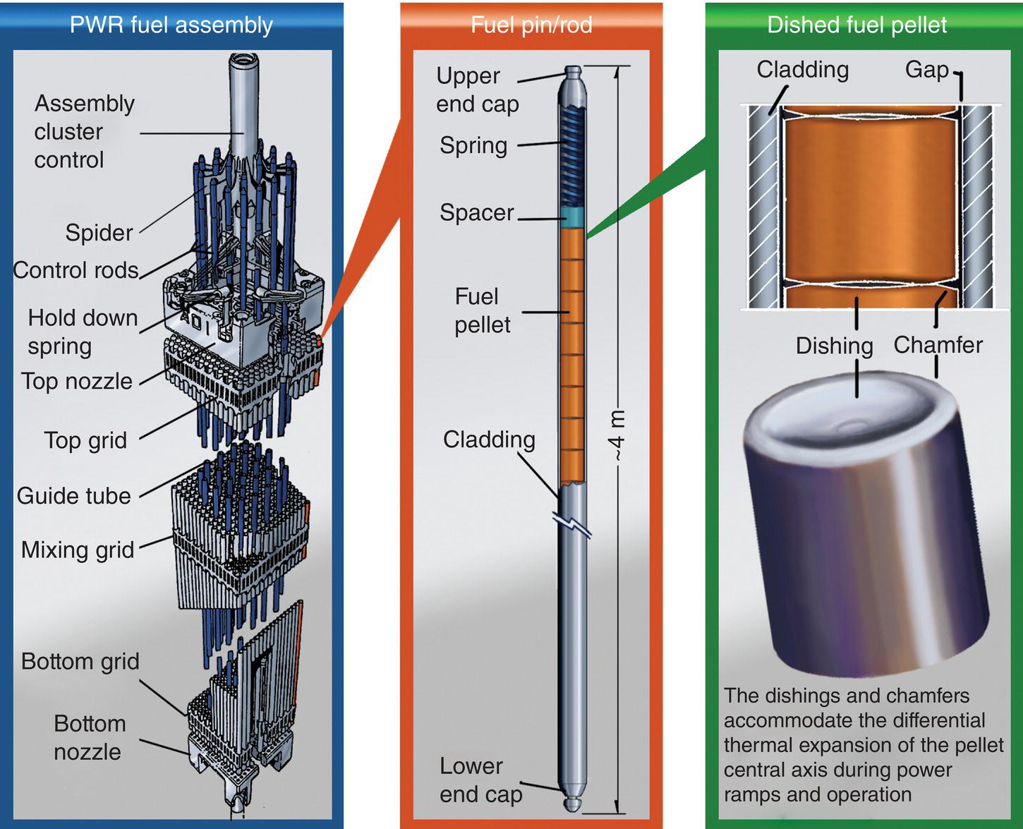
Figure 15.2. Schematic of a 17 × 17 PWR Fuel assembly with inserted control cluster, fuel pin, and dished pellet.
In addition, like most ceramics, the vapor pressure of uranium dioxide increases rapidly with increasing temperature and it displays poor thermal shock resistance at low temperatures, behaving in a brittle manner at temperatures less than 1200°C. However, at temperatures above 1200°C, UO2 is no longer brittle, which leads to further discrepancy between the behavior of the pellet interior and edge, although only during abnormal or transient temperature circumstances. This leads to cracking in UO2 fuel pellets; the cracks form on initial ramp to power but will evolve further as fuel burnup proceeds.
Mixed Oxide (MOX) fuel was first developed in the late 1950s through research programs in reprocessing, as a mechanism to separate Pu from spent fuel, and in the development of fast reactor systems, to burn Pu as fuel. With the shutdown of the majority of fast reactor programs over the last 30 years, the only remaining option for the recycling of Pu was based upon the burning of Pu in LWRs. Drawing on the fuel research undertaken for fast reactor systems, this has led to the use of MOX fuel assemblies in LWR systems. In general, MOX fabrication involves blending UO2 and PuO2 powders with a higher content of plutonium (around 30%). Then the final plutonium enrichment (3–10%) is reached by dilution with uranium dioxide. This step is followed by pressing and sintering at temperatures of approximately 1700°C to produce MOX fuel pellets. These pellets are then loaded into fuel rods, which are then grouped together to form a MOX fuel assembly, in much the same way as for conventional UO2 fuel (Fig. 15.2). After sintering, the final relative density of the pellets approaches 95%. This process is commonly called MIcronization MASter blend (MIMAS) [9]. In the future, the fabrication process may involve co-milling UO2 and PuO2 powders to directly provide the targeted Pu enrichment, ensuring better homogeneity in the nuclear fuel. Whatever the elaboration process, diffusion data are needed to achieve optimized heat treatment and develop a homogeneous Pu distribution within MOX pellets [10].
Choosing a suitable waste form to use for radioactive waste immobilization is not easy and durability is not the sole criterion [11]. A variety of matrix materials and techniques are available for immobilization. The main immobilization technologies that are available commercially and that have been demonstrated to be viable are cementation and vitrification, the latter using borosilicate glasses capable of hosting a range of radionuclides in the open glass structure. Ceramication, in which a range of crystals capable of hosting radionuclides in their structures, such as zirconolite, perovskite, and zircon, is close to commercial application [12]. Single phase systems have been examined predominantly for Pu immobilization while more complex waste streams need multiphase systems such as the Synroc ceramics developed in Australia.
While oxides/silicates are the predominant ceramics used by the nuclear industry, currently several non-oxides find key applications. Graphite is used as a moderator in many fission reactors operating today, although most are in the United Kingdom (Advanced Gas-cooled Reactors, AGR) and the countries of the former Soviet Union (water-cooled Reaktor Bolshoy Moshchnosti Kanalniy, RBMK, high power channel-type reactor). The role of graphite, in addition to mechanically supporting the fuel, is to facilitate the nuclear chain reaction by moderation of the high energy (~2 MeV) neutrons. Graphite is well suited to this role as it efficiently slows the neutrons, while being inexpensive, easily fabricated in large quantities, and compatible with the other core materials. Nuclear graphite consists of a classic grain-and-bond microstructure with a filler, binder phase, and controlled porosity. Overall porosity ranges between 14 and 21% with a few large pores constituting the majority of the overall porosity, which also has preferred orientation. Graphite remains the subject of extensive study due to its potential use as a moderator as well as a structural material in the VHTR. Boron carbide (B4C) control rods are used in all current BWRs and fast reactors to slow neutrons, enabling control of fission reactions. B4C is used because it is refractory, light weight, and chemically stabile to 2400°C, along with a large neutron absorption cross-section.
15.3 Future Nuclear Ceramics
While non-oxides are inherently more difficult to fabricate than oxide ceramics due to the need for atmosphere control, they find niche applications when they provide property benefits. UHTC properties of interest to the nuclear industry include that they may be fissile, and that they have high thermal conductivity, refractoriness, and phase stability. As a result, future nuclear ceramics will potentially include UHTCs, for example as non-oxide fuels (U/Pu carbides and nitrides) and fuel cladding (TaC, ZrC, HfC). The family of ternary compounds Mn+1AXn, where M is an early transition metal, A is an A group element, X is either C or N, and n is from 1 to 3, are known as MAX phases. MAX phases are also likely to find applications in fuel cladding, so we include them here, even though they are strictly not UHTCs. ZrB2 has already been examined as a potential neutron poison [13]. The main physical properties of these UHTCs are reported in Table 15.3.
Table 15.3. Typical properties of UHTCs
| Ceramic properties | ZrB2 | HfB2 | TaC | HfC | ZrC |
| Theoretical density (g/cm3) | 6.09 [14] | 11.20 [14] | 14.5 [14] | 12.67 [14] | 6.59 [14] |
| Melting point (°C) | 3040 [14] | 3250 [14] | 3950 [14] | 3928 [14] | 3420 [14] |
| Thermal conductivity (W/m·K) | |||||
| 25°C | 56 [15] | 100 [17] | 22.1 | 20.0 | 25 |
| 1000°C | 55 [16] | 80 | — | 25 [17] | 35 |
| Crystal structure | Hexagonal | Hexagonal | Rock salt | Rock salt | Rock salt |
| Handling | Inert | Inert | Inert/low moisture | Inert/low moisture | Inert/low moisture |
| Processing capability | Demonstrated on lab scale | Demonstrated on lab scale | Lab scale | Lab scale | Stoichiometry control issues |
| Fabrication/irradiation experience | Low | Low | Low | Low | Low |
MAX phases are attractive in nuclear structural applications in Generation IV fission and fusion reactor applications including for the former in near core fuel coating and cladding uses, so-called Accident Tolerant Fuels (ATFs). Such applications require materials able to function in extreme environments of high temperature, oxidation, stress, irradiation flux, and energy including, for example, above 1000°C in fast neutron environments. While such conditions are not those in which UHTCs are typically designed to operate, we include MAX phases here since they are advanced ceramics that will find application in future nuclear systems. They also, due to their unique crystal and microstructures, have excellent mechanical properties including high strength and toughness at elevated temperatures (Table 15.4).
Table 15.4. Typical properties of MAX phases
| Ceramic properties | Ti3SiC2 | Ti3AlC2 | Ti2AlC |
| Theoretical density (g/cm3) | 4.48 [18] | 4.25 [19] | 4.42 |
| Melting point (°C) | 3000 | Decomposes at 1460 [20] | Decomposes at 1400 [21] |
| Thermal conductivity (W/m·K) 25°C | 43 | 40 [22] | 46 |
| Strength (MPa) | |||
| RT | 580 | 760 [23] | 763 |
| 1200 °C | 260 | 195 | 270 [24] |
| Toughness (MPa·m1/2) | |||
| RT | 10 [25] | 9.1 | 6.5 |
| 1200°C | 5 | ||
| Crystal structure | Hexagonal | Hexagonal | Hexagonal |
| Handling | Air | Air | Air |
| Processing capability | Moderate, research scale | Moderate, research scale | Moderate, research scale |
| Fabrication/irradiation experience | Low | Low | Low |
15.4 Non-Oxide Nuclear Fuels
The high melting temperatures of Pu and U carbides and nitrides make them de facto UHTCs. Recent developments of non-oxide nuclear fuels have been reviewed for carbides by Sengupta et al. [26] and for nitrides by Arai [27]. Fabrication of non-oxide ceramics is inherently more difficult than oxides since it cannot be carried out in air and the products are often susceptible to oxidation. Add the additional complication of radioactivity and in some cases pyrophoric behavior and the complexity of non-oxide nuclear fuel fabrication become apparent. Nonetheless, carbide and nitride fuels are ideally suited for use in FNRs and GFRs due to their improved performance at high temperatures relative to oxide and metal fuels. Their higher fissile density gives them superior breeding characteristics, which, together with their high specific power operation, provides increased Pu production and reduced fuel cycle and power costs, with a gain in power levels over oxide fuels by a factor of 3 for carbide fuels and a factor of 4 for nitride fuels. Both fuel types can be fabricated either with a small He-bonded fuel/cladding gap or with a large Na-bonded fuel/cladding gap since interactions between fuel and cladding are problematic. These allow the fabricated fuel to be tailored to specific reactor/fuel temperature regimes to manage temperature gradients, fission gas retention, and fuel swelling in a way that effectively combines the most desirable characteristics of both oxide and metal fuels.
Thermodynamic and thermophysical properties of actinide carbides and nitrides have been recently reviewed [26, 27]. Carbide and nitride fuels exhibit higher melting points and thermal conductivity leading to lower temperature gradients within the fuel compared to oxide or metal fuels. This, in turn, leads to a reduction in the migration of fuel constituents and FPs through and out of the fuel. As a result they have been considered for higher linear power applications (up to 70 kW/m). Table 15.5 compares and summarizes the properties of carbide and nitride fuels.
Table 15.5. Properties of carbide and nitride fuels
(Adapted from Sengupta et al. [26])
| Properties | (U0.8Pu0.2)C | (U0.8Pu0.2)N |
| Theoretical density (g/cm3) | 13.58 | 14.32 |
| Melting point (°C) | 2477 | 2797 |
| Thermal conductivity (W/m·K) | ||
| 727°C | 18.8 | 15.8 |
| 1727°C | 21.2 | 20.1 |
| Crystal structure | Rock salt | Rock salt |
| Handling | Inert atmosphere | Inert atmosphere |
| Dissolution and reprocessing capability | Dissolution not simple. Not yet demonstrated on industrial scale | Dissolution easy but risk of 14C in waste management |
| Fabrication/irradiation experience | Limited | Very little |
Nitride fuel refers to a solid solution of UN and PuN, namely (U, Pu)N, in which the Pu/(U + Pu) molar ratio ranges from approximately 0.15 to −0.25. In addition, UN was developed as a potential fuel for space reactors in the United States. While interest in such fuels subsided with the demise of the global fast breeder reactor (FBR) programs in the 1980s, the solid solution of UN, PuN, and minor actinide (MA = Np, Am, and Cm) mononitride (U, Pu, MA)N has been proposed as a candidate fuel for Generation IV fast reactors. In addition, U-free nitride fuel (such as (Pu, MA)N diluted by ZrN) for MA transmutation has been extensively studied in Japan.
Compared to oxide fuels, nitride fuels, in particular, have only one moderating atom per molecule and are compatible with existing established oxide fuel fabrication and reprocessing methods, with easier dissolution in the Plutonium and URanium Extraction (PUREX) process compared to carbide fuels.
Although the nitride fuels show a higher gain in power levels, they have some disadvantages over carbides. First, they sublime or dissociate into liquid U and N2 gas at temperatures below their melting point if N2 overpressure is not maintained. Increased pressure from the build up of N2 gas can cause the fuel cell to swell and liquid U is highly corrosive to the fuel cell cladding; both factors can cause fuel assemblies to fail and have led to the use of additives such as Zr, Ti, and W to form a more stable fuel [28]. Second, the thermal neutron absorption cross-section of 14N (resulting in 14C) is high enough to reduce the breeder ratio of the fuel, although this can be addressed by enriching the 15N content of the natural N2 used in the fabrication, albeit at additional cost. The reprocessing of nitride fuels fabricated using natural N2 is also a concern as it yields significant volumes of 14C, which is biologically hazardous, although again this could be addressed by enriching in 15N. Nitride fuel is less hygroscopic than carbide fuel making processing easier, and its better dissolution in nitric acid without any Pu oxalate formation makes it compatible with hydrochemical reprocessing technology such as the established PUREX process.
Initially, melting and casting techniques or hydridation processes were used for the fabrication of carbide fuels, but they ultimately proved too expensive and produced coarse-grained pellets, not as desirable as the fine-grained pellets resulting from powder-metallurgy processes. Later, at the end of 1960s, carbothermic reduction and internal gelation routes were examined. In the carbothermic method, uranyl and plutonium oxalate feedstocks (or uranium dioxide that has been previously reduced) are converted to UO2 and PuO2 by heat treatment to decompose the oxalate and thereby remove water and carbon oxides. UO2 and PuO2 powders are then blended to an enrichment level of typically 20% Pu and mixed with carbon in the form of either carbon black or graphite. To encourage formation of a homogeneous product, the mixed powder is consolidated by briquetting before undergoing carbothermic reduction, typically by heating for several hours between 1400 and 1700°C under vacuum or inert gas because of the high carbide reactivity in air (formation of oxides) or in nitrogen (formation of nitrides) atmospheres. The (U, Pu)C product is mechanically crushed and milled to produce a powder of particle size less than 44 µm, which is pressed under approximately 410 MPa. Then, pellets are sintered in Ar/H2 at temperatures higher than 1650–1700°C to reach relative density values between 80 and 90% [29].
The method of internal gelation uses colloidal carbon in a co-conversion process to produce spherical carbide particles from nitrate feedstocks, thereby bypassing the mechanical milling, crushing, and blending processes employed in carbothermic reduction [30]. A homogeneous solution of the uranyl and plutonium nitrates is mixed with hexamethylenetetramine, urea and dispersed carbon black, and dropped into hot silicone oil to decompose the hexamethylenetetramine to ammonia. This precipitates ammonium diurinate (or plutonate) as microspheres within droplets that are washed, dried, and calcined to remove the silicone oil, solvents, and any volatiles. Sintering for 8 h at 1950°C under Ar produces carbide microspheres of greater than 95% theoretical density, which can be loaded directly into fuel pins.
Carbide fuel is a multiphase mixture of (U,Pu)C and (U,Pu)2C3 to avoid metal phase formation and to improve in-pile behavior. Indeed, a (U,Pu)C1,00 single phase cannot be elaborated from the carboreduction route because the kinetics of carbon monoxide release during the carburizing treatment are dependent on those of the densification. Furthermore, effective oxygen removal from the carbide structure requires an increase in the carboreduction temperature or the use of severe atmospheres (vacuum). These conditions promote the volatilization of species such as metallic plutonium and make compositional control difficult [31, 32]. Finally, production of biphasic carbides with very low oxygen contents (<100 ppm) is possible for low Pu/(U + Pu) atomic ratios (around 20 wt%).
Carbide fuels have been used in test reactors in, for example, the United States (EBR-II), Russia (BOR60), Japan (JFR 2), and France (RAPSODIE). The Indian FBR program started with Pu-rich mixed U,Pu carbide as the driver fuel in its loop-type fast breeder test reactor that went critical in 1985 and remains the only reactor operating on a full core of carbide fuel.
As with carbides, nitride fuels can be fabricated via a carbothermic reduction process. In the fabrication of nitride fuels, following the carbothermic reduction of the oxide to the carbide, a further reduction step is performed by soaking the carbide in N2-6% H2 gas to form the nitride and liberate the carbon in the form of methane gas [33, 34]. This nitride powder is then mechanically crushed and milled to form the feed powder for pressing as in carbide fuel fabrication. Nitride fuels have also been fabricated through a hydride-dehydride-nitride process and other sol-gel and pyrochemical processes described by Arai [27]. Before non-oxide fuels can be used in commercial reactors, further research is needed, in particular, on both hydrochemical and pyrochemical reprocessing methods, fuel-clad interaction, effects of burnup, and irradiation performance.
15.4.1 Composite Fuels
Composite fuels consisting of a fissile phase dispersed in an inert, nonfuel matrix have been developed for high temperature and/or high power density applications such as material test reactors, isotope producing reactors, and reactors developed for both power generation and propulsion in space. The two main composite fuels are CERamic METal composites (CERMETS) consisting of ceramic fuel particles dispersed in a metal matrix and CERamic CERamic composites (CERCERS) consisting of ceramic fuel particles dispersed in a ceramic matrix. In particular, a composite with a Mo metal matrix and (Pu, Np, Am, Cm)O2−x fuel particles represents a promising CERMET fuel candidate dedicated to transmutation of MA accumulated in spent fuel from LWRs [35]. Indeed, this composite fuel reduces the reactivity swing and increases the energetic efficiency of MA transmutation.
CERCER fuels in the form of pellets are often considered as replacement materials for conventional uranium dioxide pellets. Their robust nature and high burn-up performance has encouraged research on composite fuels since the 1950s, but the largest current use of composite fuels is in research and test reactors where high power density is required, often at high burnup. Composite fuels are distinguished from the usual fuel types by the localization of fuel material within an inert matrix (as opposed to a solid solution of fissile material in an inert matrix). Indeed, an advantage of the composite design is that radiation damage is primarily localized in the dispersed phase, in which case the inclusions are greater than 100 µm in size [36]. A composite fuel is shown schematically in Figure 15.3.
Figure 15.3. Schematic representations of (a) composite fuel and (b) composite fuel using a multilayer-coated fuel particle in which the coating acts as a buffer layer between the fuel particle and the matrix material.
Reproduced from Meyer [37].
Fuel particles are, in effect, individually clad in the matrix material (Fig. 15.3a), or the particles can be coated with a buffer layer (Fig. 15.3b). Encapsulation of fuel particles in a matrix prevents transport of fission gas and solid FPs outside of the local environment. Suitable matrix/buffer materials provide mechanical resistance to radiation-induced swelling. Particle dispersions are further classified as macro- and microdispersions. The particle size distribution in a macrodispersion (typically 50–200 µm) is selected to retain most of the fission fragments inside the fuel particles, leaving the majority of the matrix undamaged. Microdispersions of particles with diameters of a few microns have been considered for some concepts because of the convenience of fabrication or prevention of matrix cracking in CERCER fuels during irradiation. Macrodispersed particles may be fabricated with or without a coating layer. The simplest concept consists of a fuel particle embedded in an inert matrix. The particle may incorporate a thin barrier coating to prevent fuel-matrix chemical interaction on processing and irradiation. Such dispersions have proven effective in combination with ductile matrices such as steel or niobium. A buffer layer can be used to more effectively isolate the fuel particles from the matrix (Fig. 15.3b). The buffer layer may provide free volume for fission gas accumulation or fuel particle swelling without stressing the matrix. It may be free space, a coating, or a series of coatings. The most highly developed variants of coated particle fuel are the TRistructural ISOtropic (TRISO)2-coated fuel particles, which evolved from Bistructural ISOtropic (BISO) pellets and are discussed later. However, variants such as the QUADRISO (QUADRuple ISOtropic) concept have been suggested that incorporate an additional layer of burnable poison such as Eu2O3 [38].
TRISO fuel particles are envisaged for VHTRs considering two main fuel element concepts [39]: (1) the spherical fuel element used in the pebble-bed concept in Germany, Russia, China, and South Africa and (2) the block-type fuel element applied in the prismatic core in the United States, the United Kingdom, and Japan.
As reviewed by Sawa [40] and Petti et al. [41] the spherical fuel element is a graphitic sphere with a diameter of 60 mm composed of a fuel zone of 50 mm in diameter with around 104 coated ~0.5 mm diameter particles. The particles are overcoated with a matrix graphite layer with a thickness of around 200 µm to prevent direct contact of the particles and then dispersed uniformly in the same matrix graphite material. The outermost 5 mm of the fuel sphere is a shell of matrix graphite without any particles. The block-type fuel element in the U.S. design is a hexagonal graphite block (793 mm in length and 360 mm wide across the flat surface) containing 102 coolant channels and 210 fuel holes which are filled with fuel compacts and sealed. The fuel compacts are a mixture of TRISO-coated fissile and fertile particles and graphite shim particles bonded by a carbonaceous matrix. A fuel compact made of graphite matrix powder with the shape of an annular cylinder contains 13,500 TRISO-coated fissile particles. For operational and economic reasons, the preferred fuel kernel is low-enriched uranium dioxide for the pebble bed reactors and uranium oxycarbide for the prismatic designs.
Fuel designs for the VHTR, even though they are being developed in various countries, use the same generic refractory coated fuel particles. So, in TRISO, the actinide fuel is distributed in thousands of tiny spherical particles (Fig. 15.4).

Figure 15.4. Evolution of the coated fuel particle from uncoated to the standard TRISO and proposed QUADRISO as well as common fuel element compacts.
In TRISO, the fuel kernel is a 300–500 µm diameter sphere of UO2, UC2, or a mixture of the two which has been termed uranium oxycarbide or UCO. Kernels based on Pu or Th are also possible. The kernel is the first barrier to FP release, as FPs must first diffuse to its outer surface. Kernels are coated by chemical vapor deposition in a fluidized bed reactor. The first coating is a 60–100 µm thick buffer layer of porous pyrolytic carbon, with acetylene as the carbon source and argon as the fluidizing gas. The buffer accommodates fission gases and allows for thermal expansion mismatch between the kernel and dense coatings. The key barrier to FP diffusion is a 35–40 µm thick layer of silicon carbide, sandwiched between two dense pyrocarbon layers, each 40 µm thick. The dense pyrocarbon layers are derived from propylene in argon, while SiC is obtained from methyltrichlorosilane in hydrogen and argon. The coated TRISO particle is 0.7–0.9 mm in diameter. The SiC layer acts as a load-bearing pressure vessel and is impermeable to FP release. The inner pyrocarbon layer protects the kernel from chlorine attack during SiC deposition and the SiC from carbon monoxide generated in the kernel upon fission, while the outer pyrocarbon layer adds structural support and is a substrate for bonding to the matrix when compacted into fuel elements.
TRISO fuel fabrication routes have been reviewed by Sawa [40]. Much research is being performed on TRISO fuels for Generation IV reactors focused on extending the fuel capabilities to higher burnups (10–20%) and operating temperatures. The higher temperatures envisaged in the VHTR (fuel temperature of 1250°C) compared to the Pebble Bed Modular Reactors mean that the SiC retention layer will be inefficient and alternatives (such as ZrC) are being examined. Minato and Ogawa [42] describe advanced concepts in TRISO fuel including developments in ZrC and TiN coatings while potential fuel recycling and MA burning in these fuels are also being examined.
15.4.2 Inert Matrix Fuels
At present, the only method for the commercial recycling of Pu is as MOX fuel. Current strategies for burning MOX in LWRs are not fully optimized in terms of Pu burnup. One option to improve Pu consumption rates is to optimize reactor design to accommodate a 100% MOX core. An alternative strategy is to replace the UO2 component of the fuel with a neutron inactive or neutron transparent material—the “inert matrix”—thereby substantially reducing the capacity of the fuel for Pu production.
Strictly, an inert matrix fuel (IMF) refers to any nuclear fuel that does not contain a “fertile isotope” so that no conversion of fertile to fissile material takes place and only the initially present fissile atoms are burnt. This concept was originally aimed at improving fuel properties or to save U resources [43]. Thus, in the plutonium cycle, IMFs are those that are free from 238U, and an inert material that does not contain a fissionable or fertile isotope is used as the matrix with a plutonium-bearing material. Spent IMF is much less radiotoxic than spent MOX and so disposal is easier. IMF is also used in the context of U-free fuels for transmutation of MA, although in many cases this is inappropriate as the fissile content is inadequate for fuel purposes and it is more correct to call these systems transmutation targets. Actinide-bearing fuels and transmutation targets, including those made by adding MAs to (U,Pu)O2 at a low enough content that the performance of the fuel and core is unaffected, were discussed by Pillon [44]. The MAs form solid solutions with each other over large compositional ranges so that they are generally introduced in this form. However, the properties of actinide carbides and nitrides may make them more suitable than oxides as transmutation targets. Possible ceramic or metallic candidate materials can be chosen as IMFs using the following criteria [45]: (i) the inert matrix must be transparent to neutrons, its neutron cross-section must, therefore, be low and no FPs should be generated; (ii) specific physical properties are required such as high melting temperature. In the case of a phase transformation, the temperature must be at a value well above the operating temperature of the fuel; (iii) compatibility with neighboring materials is also a concern (cladding, coolant, fissile phase, and FPs). Indeed, new phases formed as a result of chemical reactions between the matrix and the fissile phase may lower the fuel melting temperature; (iv) the last criterion concerns the behavior under irradiation. Three main areas are of concern: the behavior of materials with respect to irradiation damage, and the thermomechanical and thermochemical behaviors. Considering these different criteria, IMFs fall into three categories [46]:
- Homogeneous fuels, in which the Pu forms a solid solution with the inert matrix. Principle candidate materials of this type of inert matrix are ceramic oxides such as ZrO2, (Y,Zr)O2 (YSZ), and CeO2. These ceramics were chosen because of the small neutron cross-section of their components, high melting points, and low reactivities with the Zircaloy cladding and reactor water [47]. A major disadvantage of these matrices is their relatively low thermal conductivities compared to UO2 at room temperature, which could induce large thermal gradients within the fuel.
- Heterogeneous particle fuels, in which the Pu particles are embedded in an inert matrix, such as MgO.
- Hybrid or composite fuels, which can either be CERCERS such as a (Y,Pu,Zr)O2−x solid solution embedded in a YSZ matrix, or CERMETS, where the metal could be Mo, Cr, Al or certain ferritic steels.
Much of the key work in this area has been performed by the CEA in France and at the European Institute for TransUranium elements (ITU) in Karlsruhe, Germany. The primary concern for any potential inert matrix material is its neutronic properties; to be consistent with the definition of an IMF, it must remain neutron transparent, typically with a thermal neutron absorption cross-section smaller than 0.2 × 10⁻²⁴ cm−2. Beyond this, typical properties for an IMF are the same as those for any fuel: suitable thermal conductivity and acceptable thermal expansion coefficient, phase stability over large temperature ranges and high irradiation doses, and inactivity with respect to FPs, reactor water, and cladding. Much like composite fuels, fabrication of IMF pellets may be achieved through one of the three routes: coprecipitation of the oxy-hydroxides from concentrated nitrate solutions of all components, a dry powder mixing/milling route, or via a sol-gel process [48].
15.4.3 Other Fuel Cladding Applications
SiCf/SiC composite ceramics (which like MAX phases are not UHTCs) are being examined as refractory cladding systems (e.g., in future GFRs as ATFs) to avoid the sort of problem that occurred at Fukushima where melting of the zircalloy cladding led to hydrogen generation and the explosions that destroyed the reactor buildings [49]. Indeed, SiCf/SiC composites show toughness six times as high as the corresponding silicon carbide monoliths. Nevertheless, the significant porosity of typical SiCf/SiC composite ceramics leads to a decrease in the thermal conductivity and to permeability to the FPs [50]. To enhance the density of composites, promising methods of synthesis being investigated include the Nanopowder Infiltration and Transient Eutectoid (NITE) process. In the same manner, replacement of SiC-based composites by high thermal conductivity ceramics such as TiC or ZrC is being examined. These latter materials show an excellent ability to retain the FPs under GFR severe accident scenarios [51].
The cladding material in GFRs is made of non-oxide ceramics but also of metallic liners (W-Re, Mo-Re, or Nb-Zr) that surround the ceramics. The inner liner is located between the nuclear fuels and ceramics and is dedicated to fission production retention [52]. The outer liner avoids migration of the helium coolant in the cladding ceramics. Increasing the number of interfaces in the fuel assembly with additional liners may lead to damaging reactions between the liner and (U, Pu)C, leading to liquid phases from 1880°C or to reactions between the SiC-based cladding materials and liner (Mo, W, Re) causing formation of low melting mixed phases at approximately 1200°C.
Hoffmann [25] examined the potential of the MAX phases Ti3SiC2, Ti3AlC2, and Ti2AlC for such applications. Many Al-containing MAX phases are stable in inert atmospheres up to >1500°C. Ti3SiC2 is stable up to 2200°C. However, on exposure to oxidizing atmospheres at high temperature, MAX phases form oxide scales, the nature of which varies with the composition of the MAX phase. In Ti2AlC, the scales are protective to 1350°C for 8000 cycles, enabling their commercial application in furnace heating elements. The oxide scales of dense polycrystalline Ti2AlC and Ti3AlC2 in air are comprised of Al2O3 and TiO2 layers at temperatures below 1200°C. At higher temperatures, Al2TiO5 forms, which has a high thermal expansion coefficient and causes cracking of the protective oxide, limiting oxidation resistance above 1400°C.
A key factor in using materials in nuclear applications is activation during use, making waste disposal challenging due to transmutation reactions leading to formation of long-lived and highly radioactive species. MAX phases were predicted and empirically observed to behave well when exposed to idealized fast and thermal reactor neutron spectra, behaving similarly to SiC and much better than potential metal alloys as they are composed of low Z elements that exhibit no long-term activation. Ti3SiC2 and Ti3AlC2 have also been observed to have high tolerances to radiation damage due to the nature of their bonding and structural ability to recover from atomic displacement damage. The combination of oxidation resistance to 1400°C, tolerance to radiation damage, good mechanical properties, ease of fabrication, and lack of activation make MAX phases strong candidates for future reactor structural applications including fuel cladding.
15.5 Other Possible Future Fission and Fusion Applications
Advances in waste separation technology [53] afford the opportunity to develop ceramic targets containing separated wastes (e.g., Minor Actinides, MA), which can then be bombarded with neutrons in a reactor or accelerator to induce transmutation and remove difficult radionuclides. International partitioning and transmutation (P&T) programs have examined ceramic transmutation targets. The differences between IMFs for burning in a reactor and P&T targets are somewhat diffuse. P&T aims at separating long-lived isotopes, followed by their nuclear transformation into shorter-lived nuclides—based in part upon the precept that this has a safety benefit with respect to waste management. Reprocessing of spent nuclear fuel when the aim is to recycle actinides as fuel (e.g., as MOX) is effectively a form of P&T (in that it reduces the proportion of radionuclides with long half-lives in the resulting waste stream). Transmutation targets come in two main forms: homogeneous actinide-containing solid solutions (e.g., (Y,Zr,Cm)O2−x and (Am,Y)N made by sol gel routes) or heterogeneous composites of sol-gel infiltrated actinide-containing particles (e.g., (Y,Zr,Cm)O2−x, (Pu,MA,Zr)O2 and (Pu,MA,Zr)N mixed with inert matrix phases such as MgO, MgAl2O4, TiN, and ZrN, then pressed and sintered). Heterogeneous fuels have the benefit of minimizing radiation-induced property changes by localizing fission heavy ion damage to isolated regions containing the MA.
While graphite moderators have been used in some reactor designs (e.g., UK AGR) and B4C control rods in others (e.g., BWRs), other large volume applications of non-oxide ceramics in current fission reactors have been limited. However, due to the far higher temperatures that will occur in, for example, the VHTR, large volumes of non-oxide, particularly graphitic and carbon-fiber reinforced carbon matrix composite (C/C) ceramics will be needed. For example, C/C composites are being examined for control rod elements in the VHTR with a focus on the impact of temperature and irradiation damage on properties and dimensional change. It has been shown that graphite material databases can be used to support evaluation of graphitised C/C [54]. In addition, SiC/SiC and C/C composites are potential candidates for blanket structural applications in Magnetic Confinement Fusion (MCF) tokamaks. The possibility of using monolithic and composite SiC thermal insulation for both fission and fusion systems is under investigation, although clearly oxidation behavior in service and in accident scenarios must be well understood [55].
Such applications require materials able to function in extreme environments including of high temperature, oxidation, stress, and irradiation flux and energy including, for example, above 1000°C in fast neutron environments. Hoffman et al. [25] examined the potential of Ti3SiC2, Ti3AlC2, and Ti2AlC for such applications. UHTCs are typically defined as ceramics designed to operate at temperatures above 2000°C, and since the U and Pu carbides and nitrides illustrated in Table 15.5 typically melt at temperatures above 3000°C they are de facto UHTCs. Significant challenges remain including understanding neutron irradiation damage and its impact on dimensions and thermal conductivity, physical sputtering, chemical erosion, radiation-enhanced sublimation, and joining of carbon fiber composites to heat sink materials. Radiation damage is a key issue in all materials that will be used in fusion reactors.
Uses of ceramics in fusion reactor systems will be both functional (such as the ceramic superconductors in the magnet systems for controlling the plasma) and structural in various locations outside of the first wall in MCF including use of single-crystal sapphire in diagnostic windows and ports. A recent review [56] emphasized that the plasma facing components, first wall, and blanket systems of tokamak-based fusion power plants arguably represent the single greatest materials engineering challenge of all time. Wirth et al. [56] highlighted the numerous multiscale modeling grand challenges, in particular the plasma materials interactions, the extreme heat and particle flux environments and complexity of extracting the tritium from breeder blankets, and the large and time-varying thermomechanical stresses in structural materials all subject to 14.1 MeV neutrons causing extensive irradiation damage, which has significant effects on thermal, mechanical, and electrical properties. Snead and Ferraris [57] highlight the current use and future potential for carbon as a plasma facing material in tokamaks. Potential fusion applications of UHTCs include tokamak diverters and plasma facing materials.
15.6 Thermodynamics of Nuclear Systems
Determination of accurate phase equilibria and thermochemical behavior in such fuels is challenging for several reasons: (i) 60 elements are generated by actinide fission, (ii) complex metals and oxide solid solutions are formed, (iii) thermally and compositionally driven transport processes result in compositional inhomogeneities, and (iv) radiation effects in such complex phases are not well understood. Relationships among components in these complex and radioactive phases are defined only for a few systems. To begin to address such problems, an assessed database of phase equilibria and thermochemical values is required, as have been developed via the European Actinet and F-Bridge programs leading to the FUELBASE database for advanced nuclear fuel materials systems such as U-Pu-O-C, U-Pu-Am-Np-O, and U-Pu-Si-C [58].
The FUELBASE thermodynamic database is based on critical assessments and on the modeling of binary and ternary systems using the calculation of phase diagrams (CalPhaD) method, allowing further developments of higher order systems. This method relies on the Gibbs energy evaluation of each phase, as simple in appearance as pure elements [59], stoichiometric compounds (SSUB, SGTE) [60], and solid solutions. The Gibbs energy function of a specific phase is evaluated as polynomial expressions of the temperature. Various models are used for the chemical description of the considered phase (mainly related to crystallographic and ordering considerations) [61].
This database could be used for equilibrium calculations, representative of different steps in fuel processing from the fabrication to the behavior in operation, the interactions between the fuel and the selected cladding material, and also for different scenarios (nominal and off-normal operating conditions). It also allows selection of different materials based on possible interactions (solubility, formation of an undesired compound or a liquid phase). Besides the systems concerning U- and Pu-based kernels themselves, this database includes ceramic systems for cladding or structural materials and takes into account possible interactions between all these constituents with the fuel kernel.
This thermodynamic database represents an important modeling effort that allows the selection of materials for specific operating conditions without dedicated hazardous and difficult experiments (radioactivity, use of shielded cells, etc.). Currently, fundamental understanding of irradiated fuel chemistry as a function of temperature and burnup is not possible. FPs are not included, and minor actinide (Am, Np, Cm) introduction to the database is on-going.
The CalPhaD method reveals the stability domains of GFR reactor fuels. For example, the multiphase carbide fuel (U,Pu)C + (U,Pu)2C3 appears to be the most stable with no trace of free carbon and liquid phase under argon up to 1973 K. This last temperature could be correlated to that of the incidental conditions or could be related to the presence of heat points. From this temperature, a liquid phase could be evidenced in equilibrium with the two carbides (Fig. 15.5).
Figure 15.5. C-Pu-U isothermal section at 1973 K.
Reproduced from Guéneau et al. [8].
From thermodynamic calculations, the interactions between fuel and cladding materials in the GFR context could be studied. For a UC fuel embedded in a SiC inert matrix, phase diagram modeling has confirmed that no interaction occurs at the usual operating temperature, or at a higher temperature of 1600°C for a C-rich UC fuel (Fig. 15.6).
Figure 15.6. C-Si-U isothermal section at 1673 K.
Reproduced from Rado et al. [62].
In contrast, for a nitride-based fuel like UN and a SiC cladding material, the thermodynamic approach shows that a U-Si intermetallic phase appears at 1723 K. At higher temperature, a liquid phase appears, thus prohibiting the use of this UN/SiC cladding couple [63].
15.7 Conclusions
The melting temperatures of current oxide and future non-oxide nuclear fuels make them de facto UHTCs. Other UHTCs as well as non-UHTCs such as MAX phases and SiC/SiC will undoubtedly find application in future fission and fusion reactor systems due to their ability to survive severe conditions of temperature, atmosphere, and radiation damage. Development of complex composite ceramics and careful consideration of thermodynamic aspects will be key to their development.
References
- 1. Carre F, Yvon P, Anzieu P, Chauvin N, Malo J-Y. Update of the French R&D strategy on gas-cooled reactors. Nucl Eng Des 2010;240:2401–2408.
- 2. Lee WE, Gilbert M, Murphy ST, Grimes RW. Opportunities for advanced ceramics and composites in the nuclear sector. J Am Ceram Soc 2013;96:2005–2030.
- 3. Fink JK. Thermophysical properties of uranium dioxide. J Nucl Mater 2000;279:1–18.
- 4. Guéneau C, Chartier A, Brutzel LV. Thermodynamic and thermophysical properties of the actinide oxides. In: Konings JM, editor. Comprehensive Nuclear Materials. Volume 2, Oxford: Elsevier; 2012. p 21, 59.
- 5. Donald IW. Mechanical properties. In: Waste Immobilization in Glass and Ceramic Based Hosts. Chichester: John Wiley & Sons Ltd; 2010. p 331.
- 6. Ringwood AE, Oversby V, Kesson S, Sinclair W, Ware N, Hibberson W, Major A. Immobilization of high-level nuclear reactor wastes in SYNROC: a current appraisal. Nucl Chem Waste Manage 1981;2:287–305.
- 7. Pillai CGS, George AM. Thermal conductivity of uranium dioxide. J Nucl Mater 1993;200:78–81.
- 8. Guéneau C, Dupin N, Sundman B, Martial C, Dumas J-C, Gossé S, Chatain S, De Bruycker F, Manara D, Konings RJM. Thermodynamic modelling of advanced oxide and carbide nuclear fuels: description of the U-Pu-O-C system. J Nucl Mater 2011;419:145–167.
- 9. Anderson HH, Asprey LB. US Patent 2,924,506. February 9, 1960.
- 10. Noyau S, Garcia P, Pasquet B, Roure I, Audubert F, Maitre A. Towards measuring the Pu self-diffusion coefficient in polycrystalline U0.55Pu0.45O2±x. Defect Diffus Forum 2012;323–325:203–208.
- 11. Ojovan MI, Lee WE. An Introduction to Nuclear Waste Immobilisation. Oxford: Elsevier; 2nd edn. 2014.
- 12. Burakov BE, Ojovan MI, Lee WE. Crystalline Materials for Actinide Immobilisation. Volume 1, London: Imperial College Press; 2011.
- 13. Middleburgh SC, Parfitt DC, Blair PR, Grimes RW. Atomic scale modeling of point defects in zirconium diboride. J Am Ceram Soc 2011;94:2225–2229.
- 14. Pierson HO. Handbook of Refractory Carbides and Nitrides. Westwood: William Andrew; 1996.
- 15. Guo S-Q. Densification of ZrB2-based composites and their mechanical and physical properties: a review. J Eur Ceram Soc 2009;29:995–1011.
- 16. Thompson MJ, Fahrenholtz WG, Hilmas GE. Elevated temperature thermal properties of ZrB2 with carbon additions. J Am Ceram Soc 2012;95:1077–1085.
- 17. Opeka MM, Talmy IG, Wuchina EJ, Zaykoski JA, Causey SJ. Mechanical, thermal, and oxidation properties of refractory hafnium and zirconium compounds. J Eur Ceram Soc 1999;19:2405–2414.
- 18. Barsoum MW, El-Raghy T. Synthesis and characterization of a remarkable ceramic: Ti3SiC2. J Am Ceram Soc 1996;79:1953–1956.
- 19. Zhou A, Wang C-A, Hunag Y. Synthesis and mechanical properties of Ti3AlC2 by spark plasma sintering. J Mater Sci 2003;38:3111–3115.
- 20. Chen JX, Zhou YC, Zhang HB, Wan DT, Liu MY. Thermal stability of Ti3AlC2/Al2O3 composites in high vacuum. Mater Chem Phys 2007;104:109–112.
- 21. Pang WK, Low IM, O'Connor BH, Peterson VK, Studer AJ, Palmquist JP. In situ diffraction study of thermal decomposition in Maxthal Ti2AlC. J Alloy Compd 2011;509:172–176.
- 22. Wang XH, Zhou YC. Layered machinable and electrically conductive Ti2AlC and Ti3AlC2 ceramics: a review. J Mater Sci Technol 2010;26:385–416.
- 23. Bao Y, Wang X, Zhang H, Zhou Y. Thermal shock behaviour of Ti3 AlC2 from between 200°C and 1300°C. J Eur Ceram Soc 2005;25:3367–3374.
- 24. Spencer CB, Córdoba JM, Obando N, Sakulich A, Radovic M, Odén M, Hultman L, Barsoum MW. Phase evaluation in Al2O3 fiber-reinforced Ti2AlC during sintering in the 1300°C–1500°C temperature range. J Am Ceram Soc 2011;94:3327–3334.
- 25. Hoffman EN, Vinson DW, Sindelar RL, Tallman DJ, Kohse G, Barsoum MW. MAX phase carbides and nitrides: properties for future nuclear power plant in-core applications and neutron transmutation analysis. Nucl Eng Des 2012;244:17–24.
- 26. Sengupta AK, Agarwal R, Kamath HS. Carbide fuel. In: Konings RJM, editor. Comprehensive Nuclear Materials. Volume 3, Oxford: Elsevier; 2012. p 55, 86.
- 27. Arai Y. Nitride fuel. In: Konings R, editor. Comprehensive Nuclear Materials. Volume 3, Oxford: Elsevier; 2012. p 41, 54.
- 28. Arai Y, Nakajima K. Preparation and characterization of PuN pellets containing ZrN and TiN. J Nucl Mater 2000;281:244–247.
- 29. Matthews RB, Harbst RJ. Uranium-plutonium carbide fuel for fast breeder reactors. Nucl Technol 1983;63:9–22.
- 30. Matthews RB, Hart PE. Nuclear fuel pellets fabricated from gel-derived microspheres. J Nucl Mater 1980;92:207–216.
- 31. Potter P. The volatility of plutonium carbides. J Nucl Mater 1964;12:345–348.
- 32. Anselin F, Dean G, Lorenzelli R, Pascard R. In: Russell LE, editor. Carbides in Nuclear Energy. Volume 1, London: Macmillan; 1964. p 162, 163.
- 33. Muromura T, Tagawa H. Formation of uranium mononitride by the reaction of uranium dioxide with carbon in ammonia and a mixture of hydrogen and nitrogen: I synthesis of high purity UN. J Nucl Mater 1977;71:65–72.
- 34. Muromura T, Tagawa H. Formation of uranium mononitride by the reaction of uranium dioxide with carbon in ammonia and a mixture of hydrogen and nitrogen: II. Reaction rates. J Nucl Mater 1979;80:330–338.
- 35. Uyttenhove W, Sobolev V, Maschek W. Optimisation of composite metallic fuel for minor actinide transmutation in an accelerator-driven system. J Nucl Mater 2011;416:192–199.
- 36. Chauvin N, Konings RJM, Matzke H. Optimisation of inert matrix fuel concepts for americium transmutation. J Nucl Mater 1999;274:105–111.
- 37. Meyer MK. Composite fuel (CERMET, CERCER). In: Konings JM, editor. Comprehensive Nuclear Materials. Volume 3, Oxford: Elsevier; 2012. p 257–273.
- 38. Talamo A, Pouchon MA, Venneri F. Alternative configurations for the QUADRISO fuel design concept. J Nucl Mater 2009;383:264–266.
- 39. Zhou XW, Tang CH. Current status and future development of coated fuel particles for high temperature gas-cooled reactors. Prog Nucl Energy 2011;53:182–188.
- 40. Sawa K. TRISO fuel production. In: Konings RJM, editor. Comprehensive Nuclear Materials. Volume 3, Oxford: Elsevier; 2012. p 143, 149.
- 41. Petti DA, Demkowicz PA, Maki JT, Hobbins RR. TRISO-coated particle fuel performance. In: Konings RJM, editor. Comprehensive Nuclear Materials. Volume 3, Oxford: Elsevier; 2012. p 151, 213.
- 42. Minato K, Ogawa T. Advanced concepts in TRISO fuel. In: Konings JM, editor. Comprehensive Nuclear Materials. Volume 3, Oxford: Elsevier; 2012. p 215, 236.
- 43. Pöml P, Konings RJM, Somers J, Wiss T, de Haas GJLM, Klaassen FC. Inert matrix fuel. In: Konings RJM, editor. Comprehensive Nuclear Materials. Volume 3, Oxford: Elsevier; 2012. p 237, 256.
- 44. Pillon S. Actinide-bearing fuels and transmutation targets. In: Konings RJM, editor. Comprehensive Nuclear Materials. Volume 3, Oxford: Elsevier; 2012. p 109, 141.
- 45. Chauvin N, Pelletier M. Inert matrix fuels. In: Buschow KHJ, editor. Encyclopedia of Materials: Science and Technology. Oxford: Elsevier; 2001. p 4066, 4068.
- 46. Schram RPC, van der Laan RR, Klaassen FC, Bakker K, Yamashita T, Ingold F. The fabrication and irradiation of plutonium-containing inert matrix fuels for the “Once through then out” experiment. J Nucl Mater 2003;319:118–125.
- 47. Ledergerber G, Degueldre C, Heimgartner P, Pouchon MA, Kasemeyer U. Inert matrix fuel for the utilisation of plutonium. Prog Nucl Energy 2001;38:301–308.
- 48. Konings RJM, Bakker K, Boshoven JG, Hein H, Huntelaar ME, van der Laan RR. Transmutation of actinides in inert-matrix fuels: fabrication studies and modelling of fuel behaviour. J Nucl Mater 1999;274:84–90.
- 49. Farid O, Shih K, Lee W, Yamana H. Fukushima: the current situation and future plans. In: Lee WE et al., editors. Radioactive Waste Management and Contaminated Site Clean-up: Processes, Technologies and International Experience. Oxford: Woodhead Pub Ltd.; 2013.
- 50. Cabrero J, Audubert F, Pailler R, Kusiak A, Battaglia JL, Weisbecker P. Thermal conductivity of SiC after heavy ion irradiation. J Nucl Mater 2010;396:202–207.
- 51. Gutierrez G, Toulhoat N, Moncoffre N, Pipon Y, Maître A, Gendre M, Perrat-Mabilon A. Thermal behaviour of xenon in zirconium carbide at high temperature: role of residual zirconia and free carbon. J Nucl Mater 2011;416:94–98.
- 52. Viaud C, Maillard S, Carlot G, Valot C, Gilabert E, Sauvage T, Peaucelle C, Moncoffre N. Behaviour of helium after implantation in molybdenum. J Nucl Mater 2009;385:294–298.
- 53. Nash KL, Lumetta GJ. Advanced Separation Techniques for Nuclear Fuel Reprocessing and Radioactive Waste Treatment. Oxford: Woodhead Publishing; 2011. Series in Energy No. 2.
- 54. Shibata T, Sumita J, Sawa K, Takagi T, Makita T, Kunimoto E. Irradiation-induced property change of C/C composite for application of control rod elements of Very High Temperature Reactor (VHTR). Proceedings of the Structural Materials for Innovative Nuclear Systems (SMINS-2), OECD Nuclear Energy Agency (NEA Report n. 6896); August 31–September 3, 2010; Daejon, Republic of Korea; 2010.
- 55. Snead LL, Katoh Y, Nozawa T. Radiation effects in SiC and SiC–SiC. In: Konings RM, editor. Comprehensive Nuclear Materials. Volume 4, Oxford: Elsevier; 2012. p 215, 240.
- 56. Wirth B, Nordlund K, Whyte D, Xu D. Fusion materials modeling: challenges and opportunities. Mater Res Soc Bull 2011;36:216–222.
- 57. Snead LL, Ferraris M. Carbon as a fusion plasma-facing material. In: Konings RJM, editor. Comprehensive Nuclear Materials. Volume 4, Oxford: Elsevier; 2012. p 583, 620.
- 58. Guéneau C, Gossé S, Chatain S, Utton C, Dupin N, Sundman B, Martial C, Dumas J-C, Rado C. 2008. FUELBASE: a thermodynamic database for advanced nuclear fuels. Best poster award, Calphad Meeting 2008. Available at http://www.calphad.org/awards/2008-Best-Poster.pdf. Accessed July 1, 2014.
- 59. Dinsdale AT. SGTE data for pure elements. Calphad 1991;15:317–425.
- 60. SGTE Substances Database. 2013. Available at http://www.thermocalc.com/TCDATA.htm. Accessed July 01, 2014.
- 61. Lukas HL, Fries SG, Sundman B. Computational Thermodynamics: The Calphad Method. Cambridge: Cambridge University Press; 2007.
- 62. Rado C, Rapaud O, Chatain C, Guéneau C, Guyadec F, Deschamps B. Développement du combustible des futurs réacteurs rapides à gaz. etude de la compatibilité entre composé fissile et matrice inerte. Proceedings of the Materiaux 2006, Dijon, November 13–17, 2006.
- 63. Guéneau C, Chatain S, Gossé S, Rado C, Rapaud O, Lechelle J, Dumas JC, Chatillon C. A thermodynamic approach for advanced fuels of gas-cooled reactors. J Nucl Mater 2005;344:191–197.