16
UHTC-Based Hot Structures: Characterization, Design, and On-Ground/In-Flight Testing
Davide Alfano1, Roberto Gardi1, Luigi Scatteia2, and Antonio Del Vecchio1
1 Italian Aerospace Research Centre (CIRA), Capua (CE), Italy
2 Booz & Company B.V., Amsterdam, the Netherlands
16.1 Introduction
Passive thermal protection systems (TPS) for hypersonic vehicles are essential to protect cold structures from high heat fluxes during the reentry phase into the Earth's atmosphere. TPS materials fall into two broad categories: ablative and reusable.
Ablative materials as TPS were employed in the Apollo program [1–3]. Thermal protection is achieved through endothermic chemical processes such as melting, sublimation, or pyrolysis of ablative materials, which are usually low thermal conductivity insulators such as carbon phenolic composites. Reusable TPS must withstand aerodynamic loads at very high operational temperatures reached during reentry. Among reusable TPS are monolithic ceramics and ceramic matrix composites such as carbon fiber reinforced silicon carbide composites (C/SiC) [4, 5]. Ceramic compounds based on the metal borides, such as zirconium diboride (ZrB2) and hafnium diboride (HfB2), are commonly referred to as Ultra-High-Temperature Ceramics (UHTCs). This class of materials is promising for use in extreme environments, such as sharp leading edges hot structures on future-generation slender-shaped reentry vehicles, because of their high melting points (ZrB2 3040°C, HfB2 3250°C) and relatively good oxidation resistance in reentry conditions [6–10].
In the framework of the unmanned space vehicle (USV) project funded by the Italian Aerospace Program (PRORA) and within various other European programs, since 2000 the Italian Aerospace Research Centre (CIRA) has studied, developed, and tested monolithic UHTCs to employ as passive structural TPS [11–14], henceforth referred to as hot structures. In Figure 16.1 CIRA's roadmap of experimental activities performed on hot structures in the last 10 years is summarized.
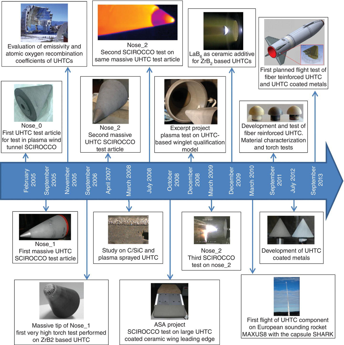
Figure 16.1. CIRA activities on UHTCs for thermal protection systems.
16.2 TPS: Test Articles and Prototypes
In the framework of the internal CIRA project named sharp hot structure (SHS), three full scale nose caps characterized by small curvature radii for vehicle reentry from LEO (low Earth orbit) were designed, manufactured, and then tested at high stagnation point heat flux. The nose caps were identified as Nose_0, 1, and 2.
The test article Nose_0 was a cone relatively small in size (height 174 mm and diameter 127 mm) constructed with a graphite core and an external layer of C/SiC (thickness 5 mm) applied by chemical vapor infiltration. The oxidation resistance of the structure was improved by a plasma-sprayed ZrB2-based UHTC coating. Plasma deposition was carried out by an 80 kW plasma torch, which allows depositions in the pressure range 10–400 kPa under air or inert atmosphere. The protective coating was obtained starting from a mixture of ZrB2 and SiC powders with 75 and 25 wt%, respectively (more details on deposition process are described in Refs. [15–17]). That composition was selected to obtain a coating with good oxidation resistance. Previous studies have described how the addition of SiC, used also as sintering aid, provides significant improvement to the oxidation resistance of monolithic ZrB2-based UHTCs [18]. Although Nose_0 only employs UHTC materials in form of a coating, its manufacturing allowed CIRA to familiarize with the fabrication of C/SiC components, the deposition of UHTC by plasma spraying on axially symmetric structures, the design and manufacturing of a mechanical interface with a cold structure, and then with the testing of a SHS in the plasma wind tunnel (PWT) “Scirocco” (see Section 16.3).
Noses_1 and 2 were manufactured to obtain and then study more complex test articles wherein topics such as the attachment of massive UHTCs and C/SiC composites to substructures or the deposition of UHTC-based coatings on relatively large and complex shaped structures were faced.
Nose_1 and Nose_2 consisted of a monolithic ZrB2-based UHTC conical nose tip with height of 100 mm attached to a truncated cone base (height 404 mm and diameter 304 mm) with a graphite core and an external layer of C/SiC (Fig. 16.2). The same UHTC coating (ZrB2 and SiC with 75 and 25 wt%) was deposited by plasma spray on the truncated cone bases of both prototypes in order to improve their oxidation resistance. In the case of Nose_1, coating adhesion to the C/SiC substrate was not uniform due to the relatively large coating thickness of about 1 mm. These adhesion problems were not observed on the C/SiC base of Nose_2 where the coating thickness was reduced to about 300–500 µm.
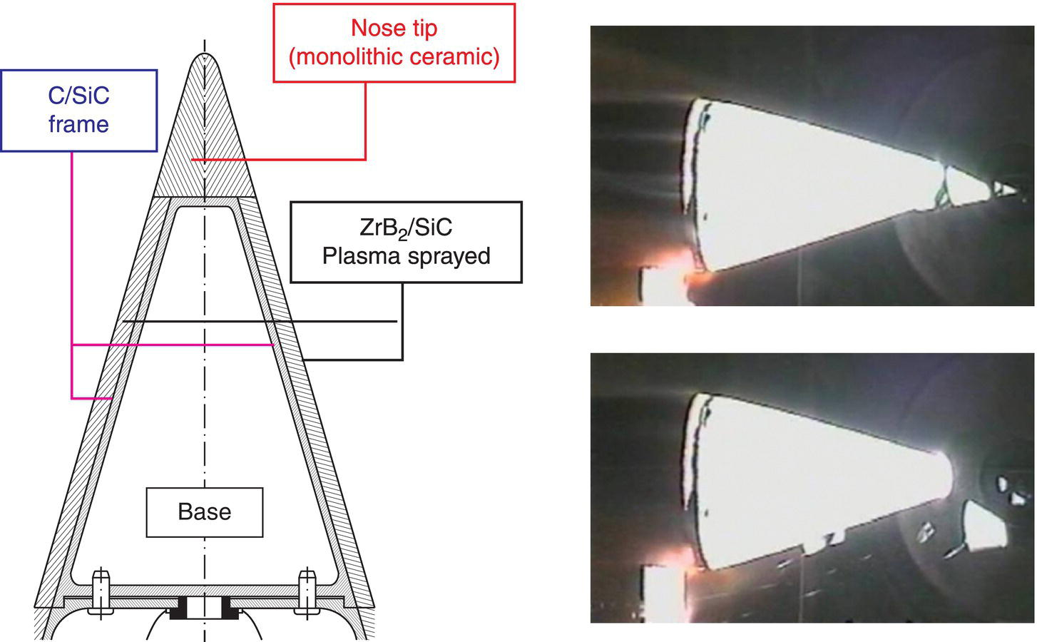
Figure 16.2. Configuration of test articles. Nose_1: breaking of nose tip during the plasma test.
The chemical composition of the monolithic nose tips is the main difference between Nose_1 and Nose_2: ZrB2 + 15 vol% SiC + 2 vol% MoSi2 (ZS) in the former and ZrB2 + 10 vol% HfB2 + 15 vol% SiC + 2 vol% MoSi2 (ZHS) in the latter.
SiC addition was found to improve the processing by lowering sintering temperatures of diborides-based UHTCs [19–21] and improving the oxidation resistance. In fact the oxidation of pure ZrB2 above 1200°C produces B2O3 which, being characterized by intensive volatility, is not able to form a stable and protective oxide scale [22–28]. The addition of SiC enhances resistance to the oxidation of diborides-based monolithic ceramics up to 1600°C through the formation of borosilicate glass [18, 24–26, 29–43].
Nose cone tips were manufactured by uniaxial hot-pressing in vacuum starting from powder mixtures containing MoSi2 as a sintering aid. Peak temperatures, dwell times, and applied pressures were 1820°C/15 min/30 MPa for material ZS, and 1900–1940°C/45 min/40 MPa for material ZHS, with an average heating rate of 20°C/min. The relatively high electrical conductivity of ZS and ZHS compositions allows the final shapes in both nose tips to be fabricated from sintered billets by electrical discharge machining (EDM). Although EDMed surfaces had a higher roughness with respect to diamond-loaded tooled (DLTed) ones [44], EDM has proven to be an effective and flexible technique to machine UHTC sintered pieces into complex components. Thermomechanical and physical properties of ZS and ZHS formulations obtained by CIRA are summarized in Table 16.1.
Table 16.1. Thermomechanical and physical properties of ZrB2 + 15 vol% SiC + 2 vol% MoSi2 (ZS) and ZrB2 + 10 vol% HfB2 + 15 vol% SiC + 2 vol% MoSi2 (ZHS) formulations [45]
| Property | ZS | ZHS | ||
| Density (kg/m3) | 5610 ± 10 | 6060 ± 15 | ||
| Porosity (%) | <1 | <1 | ||
| Specific heat | T (K) | CP (J/g·K) | T (K) | CP (J/g·K) |
| 298 | 0.46 ± 0.01 | 298 | 0.52 ± 0.02 | |
| 500 | 0.60 ± 0.02 | 500 | 0.67 ± 0.02 | |
| 1000 | 0.70 ± 0.02 | 1000 | 0.76 ± 0.02 | |
| 1500 | 0.75 ± 0.02 | 1500 | 0.81 ± 0.02 | |
| 2000 | 0.79 ± 0.02 | 2000 | 0.84 ± 0.02 | |
| Total hemispherical emissivitya (measurement performed on EDMed sample at 200 Pa) | T (K) | Emissivity | T (K) | Emissivity |
| 1037 | 0.77 ± 0.04 | 1144 | 0.56 ± 0.10 | |
| 1169 | 0.71 ± 0.03 | 1434 | 0.73 ± 0.07 | |
| 1250 | 0.72 ± 0.04 | 1733 | 0.72 ± 0.10 | |
| 1319 | 0.73 ± 0.04 | |||
| 1485 | 0.75 ± 0.04 | |||
| 1681 | 0.72 ± 0.04 | |||
| Total hemispherical emissivitya,b (measurement performed on EDMed samples at 10 Pa) | T (K) | Emissivity | T (K) | Emissivity |
| 1099 | 0.53 ± 0.03 | 1171 | 0.50 ± 0.03 | |
| 1170 | 0.66 ± 0.03 | 1366 | 0.74 ± 0.04 | |
| 1418 | 0.81 ± 0.04 | 1533 | 0.81 ± 0.04 | |
| 1609 | 0.76 ± 0.04 | 1720 | 0.75 ± 0.04 | |
| 1865 | 0.66 ± 0.03 | |||
| Atomic oxygen recombination coefficientb,c (γ) (measurement performed on EDMed sample at 200 Pa) | T (K) | γ ×10−2 | T (K) | γ ×10−2 |
| 850–1200 | 0.8 ± 0.2 | 1000 | 3.0 ± 0.9 | |
| 1400 | 1.6 ± 0.5 | 1200 | 5.4 ± 1.6 | |
| 1600 | 1.7 ± 0.5 | 1400 | 6.5 ± 1.9 | |
| 1800 | 1.9 ± 0.6 | 1600 | 9.2 ± 2.8 | |
| 2000 | 2.9 ± 0.9 | 1800 | 9.7 ± 2.9 | |
| Total hemispherical emissivitya,b (measurement performed on DLTed sample at 10 Pa) | T (K) | Emissivity | T (K) | Emissivity |
| 1188 | 0.53 ± 0.03 | 1168 | 0.49 ± 0.02 | |
| 1397 | 0.71 ± 0.04 | 1422 | 0.62 ± 0.03 | |
| 1595 | 0.76 ± 0.04 | 1600 | 0.70 ± 0.04 | |
| 1720 | 0.73 ± 0.04 | 1701 | 0.71 ± 0.04 | |
| Atomic oxygen recombination coefficientb,c (γ) (measurement performed on DLTed sample at 200 Pa) | T (K) | γ ×10−2 | T (K) | γ ×10−2 |
| 1000 | 2.4 ± 0.7 | 1000 | 1.6 ± 0.5 | |
| 1200 | 4.4 ± 1.2 | 1200 | 4.0 ± 1.2 | |
| 1400 | 5.6 ± 1.7 | 1400 | 6.9 ± 2.1 | |
| 1600 | 7.7 ± 2.3 | 1600 | 10.5 ± 3.1 | |
| 1800 | 9.5 ± 2.8 | 1800 | 11.5 ± 3.4 | |
| Thermal conductivity (uncertain 7%) | T (K) | λ (W/m·K) | T (K) | λ (W/m·K) |
| 303 | 62.47 | 303 | 79.87 | |
| 523 | 64.02 | 523 | 83.14 | |
| 1023 | 64.83 | 1023 | 83.88 | |
| 1473 | 65.18 | 1473 | 85.03 | |
| Vickers hardness HV1.0 (GPa) | 17.7 ± 0.4 | 18.2 ± 0.5 | ||
| Fracture toughness KIC (MPa·m1/2) | 4.07 ± 0.03 at 298 K 2.5 ± 0.2 at 1773 K | 4.1 ± 0.7 at 298 K | ||
| Young modulus (GPa) | 480 ± 4 | 506 ± 4 | ||
| Flexural strength (MPa) | 8.9 ± 1.2 E + 02 at 298 K | 7.6 ± 0.7 E + 02 at 298 K | ||
| 2.5 ± 0.2 E + 02 at 1773 K | 2.4 ± 0.2 E + 02 at 1773 K | |||
| Poisson's ratio | 0.13 | 0.13 | ||
| CTE (cm/cm⋅K) | T (K) | CTE (×10−6) | T (K) | CTE (×10−6) |
| 1073 | 6.67 | 1073 | 6.74 | |
| 1173 | 6.79 | 1173 | 6.85 | |
| 1273 | 6.95 | 1273 | 7.00 | |
| 1373 | 7.02 | 1373 | 7.09 | |
| 1473 | 7.01 | 1473 | 7.20 | |
| 1573 | 7.11 | 1573 | 7.24 | |
a Total hemispherical emissivity: values obtained by angular integration (0°–80° by 10° step) of the directional emissivity measured in the wavelength range of 0.6–40 µm (for more details see References [48, 49]).
b Data from Reference [44].
c Atomic oxygen recombination coefficient: method and experimental set-up are described in Refs. [50, 51].
For use as hot structures, parameters such as emissivity (ratio of surface radiance to blackbody radiance at the same temperature and wavelength) and catalicity need to be evaluated in addition to characterizing the conventional thermomechanical properties measurements. Emissivity can become the main mechanism for heat dissipation at high altitudes during reentry phase, when convection is low. Catalicity is also important since while crossing the atmosphere, a space vehicle creates a shock wave leading to very high temperatures from recombination of excited and ionized species (atoms, molecules, ions, and electrons).
The key parameter for describing surface catalicity is the recombination coefficient, γ, which is defined as:

where Nr is the number of atoms that recombine on a surface per unit area and time, and N is the number of atoms striking the surface per unit area and time.
Since 2005, hemispheric emissivity and atomic oxygen recombination coefficients of UHTCs were obtained through different experimental campaigns carried out at PROMES-CNRS laboratories [44, 46, 47] using MEDIASE (Moyen d'Essai et de DIagnostic en Ambiance Spatiale Extrême) [48, 49] and MESOX (Moyen d'Essai Solaire d'Oxydation) [50, 51]. Nose_1 and Nose_2 prototypes were tested in PWT “Scirocco” wherein heat flux up to 4.5 MW/m2 was reached for a total duration of about 4 min. Details and results from these plasma tests are described in Section 16.3.
From the perspective of chemical reactions and thermodynamics, on-ground qualification and characterization of aerospace materials cannot reproduce all aspects of the hypersonic flight environment. Hence, to close the loop between scientific knowledge and the mutual relationship among theoretical, on-ground, and flight research, materials must be tested in real flight conditions. For this purpose, the Nose_1 and Nose_2 formulations were also used to manufacture test articles for the technological projects EXPERT (European eXPErimental Reentry Test-bed) and SHARK (Sounding Hypersonic Atmospheric Reentering “Kapsule”). These two projects provided a means of evaluating UHTC-based thermostructural components under real flight conditions.
In the frame of the European Space Agency (ESA) Program EXPERT, CIRA developed a scientific payload to test a UHTC structure in flight. The objective was to design, manufacture, and test a structural subcomponent. Two small winglets were made of ZS (same composition of Nose_1 tip). They were in a dimension of 5 × 10 cm and mounted on the external surface of the capsule where they would be exposed to the high energy air flow of the suborbital reentry trajectory [52], which is described in more detail in Section 16.4.
SHARK is a small capsule designed and built at CIRA under an ESA contract. The aim of the project was to prove the viability of a low-cost experimental space platform and execute a reentry test flight by dropping a capsule from a sounding rocket. The capsule comprised of a stainless steel frontal shield with a UHTC nose tip machined from the Nose_2 (ZHS) prototype after its ground test in the PWT “Scirocco.” The technical details of this flight experiment and the experimental findings are described in Section 16.5.
In the frame of the Advanced Structural Assembly (ASA) project, funded by Agential Spaziale Italiana (ASI), a full scale technological demonstrator (the forepart of a wing leading edge) was designed, manufactured, and then tested in the PWT. The base formulation was a ceramic material lighter than the UHTCs used in nose prototypes. The composition had a higher damage tolerance (a requirement for large-scale monolithic ceramic components), but with lower chemical stability at high temperatures, which was improved by a UHTC coating.
A wide characterization campaign was performed on different ceramic compositions to select the formulation with higher values of fracture toughness and thermal shock resistance. These properties were evaluated through the measurement of four-point residual flexure strength [53] after quenching in water (thermal shock up to 900°C). Based on materials requirements defined by ASA project, the compositions listed in Table 16.2 were selected and then characterized.
Table 16.2. Ceramic formulations and related densification processes: hot-pressing (HP) and pressureless sintering (PLS)
| ID | Basic composition (vol%) | Densification process |
| Z3M | ZrB2 + 3 MoSi2 | HP |
| RAY2535M | Si3N4 + 35 MoSi2 | HP |
| Z20M | ZrB2 + 20 MoSi2 | PLS |
| ASM30 | AlN + 30 MoSi2 + 15 SiC | PLS |
Processing conditions for pressureless sintering were flowing inert gas, a heating rate of 10°C/min, and temperatures up to 1900°C. For hot pressing, the heating rate was about 20°C/min up to 1900°C at a pressure of 30 MPa.
The selected composition for the bulk ceramic part of the leading edge was Si3N4 + 35 vol% MoSi2 + 2.5 vol% Y2O3 + 1 vol% Al2O3 (RAY2535M). Compared to the other formulations, this composition had the highest flexure strength values that were retained even after a thermal shock temperature drop of 650°C. In Table 16.3, the values of some thermomechanical properties of RAY2535M are reported.
Table 16.3. Thermomechanical properties of massive Si3N4 + 35 vol% MoSi2 + 2.5 Y2O3 + 1 Al2O3 (RAY2535)
| Properties | Si3N4 + 35 vol% MoSi2 + 2.5 Y2O3 + 1 Al2O3 | |
| Density (kg/m3) | 4200 at 298 K | |
| 4216 at 873 K | ||
| 4235 at 1573 K | ||
| Specific heat | T (K) | CP (J/g·K) |
| 298 | 0.567 | |
| 573 | 0.717 | |
| 1073 | 0.787 | |
| 1573 | 0.832 | |
| Thermal diffusivity | T (K) | DTH (cm2/s) |
| 298 | 0.131 | |
| 573 | 0.073 | |
| 1073 | 0.048 | |
| 1573 | 0.039 | |
| Thermal conductivity | T (K) | KTH (W/m·K) |
| 298 | 31.2 | |
| 573 | 22.0 | |
| 1073 | 15.8 | |
| 1573 | 13.7 | |
| Elastic modulus (GPa) | 328 | |
| Microhardness (GPa) | 15.8 ± 0.2 | |
| Fracture toughness KIC (MPa·m1/2) | 6.0 ± 0.2 at 298 K | |
| CTE (10−6/K) | 6.5; 298–1573 K | |
| Flexural strength (MPa) | 915 ± 65 at 298 K | |
| 755 ± 90 at 1273 K | ||
| 250 ± 28 at 1573 K | ||
| 148 ± 7 at 1773 K | ||
The leading edge was shaped by EDM starting from a monolithic ceramic billet. To increase oxidation resistance of the monolithic ceramic, a coating of ZrB2 + 30 vol% SiC + 10 vol% MoSi2 with a thickness of about 150 µm was applied by plasma spray on the leading edge surface. That composition was selected among different coating formulations after a wide experimental characterization campaign in which morphological structure, adhesion to the selected massive ceramic substrate, and oxidation resistance (assessed by plasma torch test under high enthalpy flow conditions—maximum temperatures reached were about 1750°C) were evaluated.
At the same time as technology research in prototype manufacturing, base material research was conducted on the reference UHTC composition (ZrB2-SiC), with the aim to improve its sinterability and oxidation resistance. In this study, LaB6 was considered as a ceramic additive. The presence of LaB6 could potentially increase the oxidation resistance ZrB2 through the formation of a refractory oxidation by-product, lanthanum zirconate (La2Zr2O7, LZ), to limit the inward diffusion of oxygen [54–56]. This compound has cubic pyrochlore structure [57] and is thermodynamically stable up to the melting point (at about 2300°C) [58]. Monolithic samples with 15 vol% SiC and different loadings of LaB6 (from 10 to 20 vol%) were sintered by hot pressing under a rough vacuum of 0.2–1 mbar. The hot pressing cycle included heating up to 1930°C with an applied pressure of 30 MPa and a heating rate of 20°C/min, followed by an isothermal hold at 1930°C for 15 min under a pressure of 40 MPa. Oxidation tests on ZrB2-LaB6-SiC based UHTC formulations were carried out by arc-jet experiments on EDMed hemispherical-shaped samples for at least 6 min at a specific total enthalpy of about 10 MJ/kg to reproduce the typical experimental conditions during the hypersonic reentry phase. Microstructural characterization showed that surface damage increased with increasing ratios of LaB6/ZrB2, making the formulation with 10 vol% of LaB6 the most resistant to oxidation. In any case, ZrB2-LaB6-SiC based ceramic formulations are characterized by lower oxidation resistance than ZS UHTCs, because a protective lanthanum zirconate layer did not form [59]. Thermomechanical properties of ZrB2 + 15 vol% SiC + 10 vol% LaB6 are summarized in Table 16.4.
Table 16.4. Thermomechanical properties of massive ZrB2 + 15 vol% SiC + 10 vol% LaB6 [59]
| Properties | ZrB2 + 15 vol% SiC + 10 vol% LaB6 | |
| Density (kg/m3) | 5500 at 298 K | |
| Porosity (%) | <0.1 | |
| Thermal conductivity | T (K) | KTH (W/m·K) |
| 300 | 129.0 | |
| 1073 | 106.7 | |
| 1773 | 97.8 | |
| Elastic modulus (GPa) | 465 | |
| Fracture toughness KIC (MPa·m1/2) | 2.8 ± 0.4 at 293 K | |
| CTE (10−6/K) | 6.95; 293–1573 K | |
| Flexural strength (MPa) | 608 ± 103 at 293 K | |
| 405 ± 30 at 1573 K | ||
16.3 Plasma Tests of Nose Test Articles
The test article Nose_0 withstood three sequential runs in the PWT “Scirocco,” with a heat flux of about 1100 kW/m2 on the stagnation point and an overall exposure time of about 140 s. After the tests, negligible changes to the external surfaces were observed. The test article Nose_1 was tested at a heat flux of 1200 kW/m2 on the stagnation point and was intended to last for 72 s. The coating sustained the thermal load, while an unexpected failure occurred to the monolithic tip. After 28 s, the monolithic tip broke into two large parts and produced several pieces of debris (Fig. 16.2). After the test, the causes of the failure were studied to identify corrective actions aimed at reproducing a second test article that would be able to sustain the thermal loads. In particular, attention was focused on the threaded hole manufactured by EDM in the monolithic nose tip to attach the nose tip to the C/SiC base using a titanium screw. Optical and electron microscopic analyses performed on the broken fragments revealed the presence of microcracks localized on the surface of the thread due to the EDM process. The low temperature at the moment of failure and the microscopic analyses led to the conclusion that the failure was caused by the concentration of micromechanical loads on microcracks present inside the tip that were in contact with the titanium screw.
As a result of the Nose_1 test results, Nose_2 fabrication was delayed and the attachment concept between tip and base was redesigned. In particular, the mechanical interface between the monolithic tip and the C/SiC base was changed to a metallic fastener preloaded with a spring, which avoided the use of any threaded pivot or hole [60]. The concept of the coupling pin is as follows: the pin is introduced into the hole and then rotated by 90° to ensure contact. The spring allows control of the applied preload even in presence of thermal expansion, minimizing stresses induced by heating. Moreover, the possibility of removing the tip allowed carrying out subsequent machining of the test article: the monolithic tip was retro-fitted with two temperature sensors and one deformation transducer based on fiber optics, without inducing stress on the ceramic tip.
Three plasma tests were performed on Nose_2. The first one was executed at the same conditions used for the test on Nose_1 and the test article sustained the heating load for the duration of the test. The second consecutive test was successfully carried out increasing the heat flux up to 2.1 MW/m2 for 108 s. The measured temperature on the stagnation point of the tip was about 1800°C; no damage was detected at the end of the test. Finally, the third run pushed the heat flux up to 4.5 MW/m2. After 30 s of exposure the test article failed dramatically.
16.4 Expert Project: Computational Fluid Dynamics Computations and Plasma Tests
The ceramic monolith winglet from the EXPERT capsule is shown in Figure 16.3.
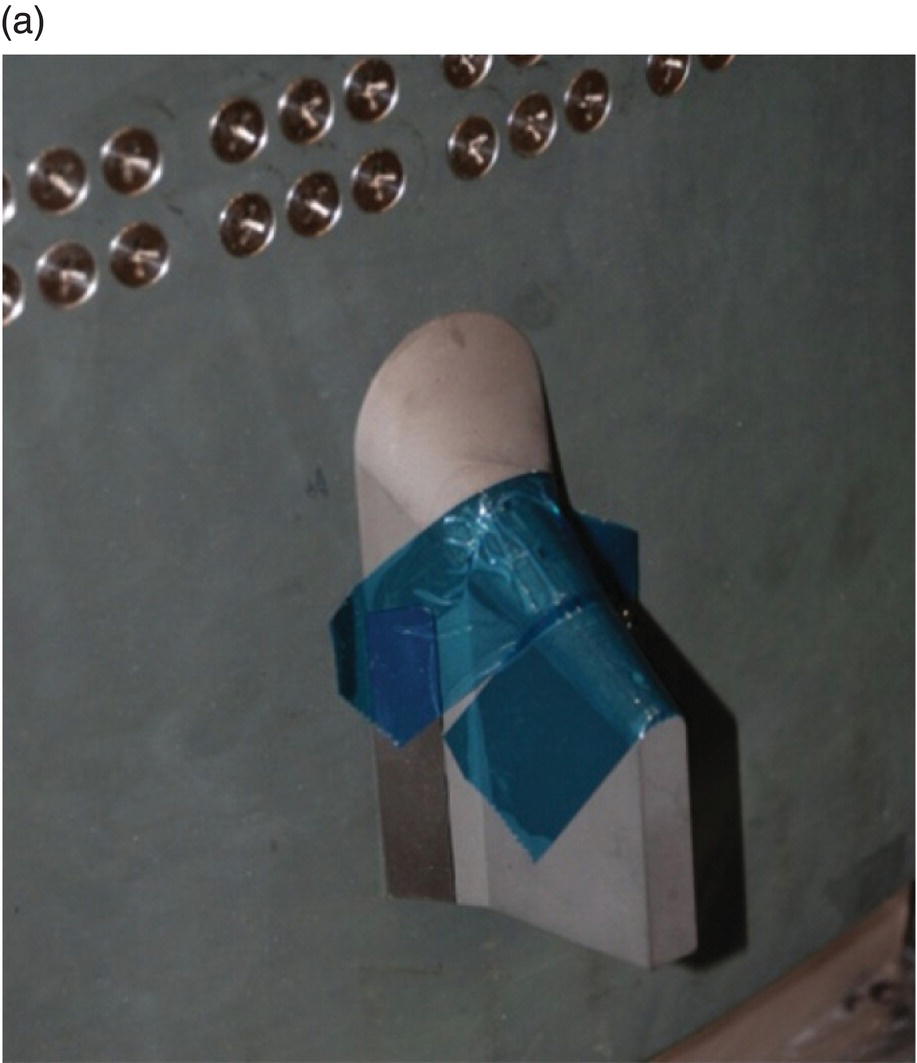
Figure 16.3. (a) Monolithic ceramic winglet flight models mounted on the EXPERT TPS and the (b) EXPERT capsule.
Computational fluid dynamics (CFD) simulations of a winglet on a flat surface similar to the capsule were carried out for the maximum peak heating foreseen during the reentry phase (altitude = 34 km, Mach = 14). The simulations used the conservative assumption of an isothermal 3D winglet (Twall = 300 K) and imposed the appropriate inlet boundary conditions and axis-symmetric field computations at the winglet locations. Figure 16.4 shows the distribution of heat flux and pressure values at the maximum heat flux conditions under the assumption of a fully catalytic wall. Evaluation of the winglet temperature was performed combining CFD analysis with a thermal model of the structure. The maximum value of temperature reached on the leading edge surface, evaluated at time of 78 s starting from an initial altitude of 100 km, was about 2130 K for a fully catalytic wall and about 1700 K for an inert wall (Fig. 16.4). In any case, the temperature of the metallic support did not exceed its maximum allowable value of about 1500 K.
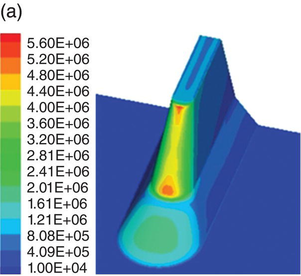
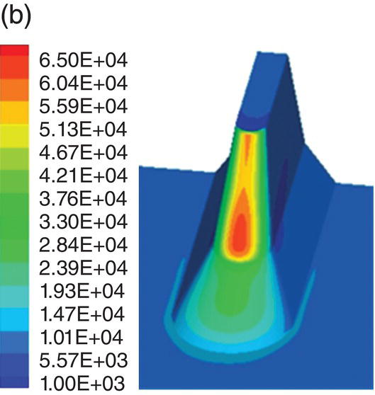
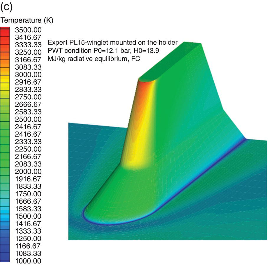
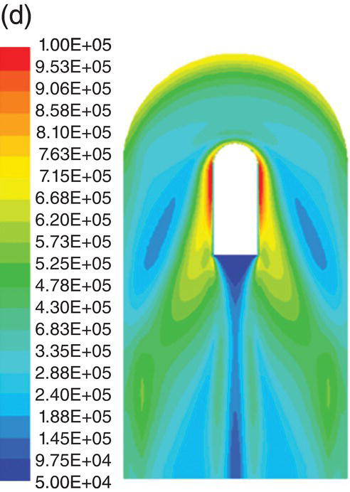
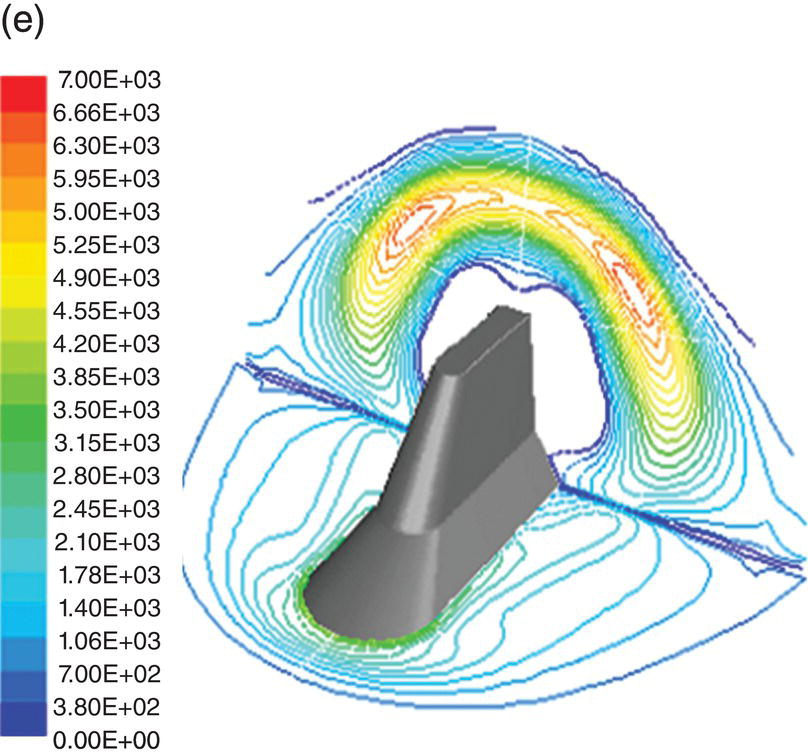
Figure 16.4. CFD analysis: (a) surface heat flux (W/m2), (b) pressure (Pa), (c) temperature (K) distributions in fully catalytic conditions, (d) heat fluxes (W/m2), and Figure 16.4. (e) pressure (Pa) disturbances around the winglet.
To evaluate the interaction of the shock wave from the winglet with the flaps, the pressure distributions on two planes (located at 1.5 cm and at 4.5 cm from the capsule surface) were calculated. Also, the pressure distributions on the capsule wall and on the plane located 10 cm from the winglet front region were evaluated. Disturbances were found to be relatively low in pressure (15 kPa) in a limited region very close to the capsule (Fig. 16.4).
One of the most challenging aspects of a flight experiment is to produce a mechanical interface that allows coupling the UHTC winglet, which is subjected to large heat fluxes and mechanical loads, to the metallic structure of the capsule. Mechanical loads are generated from the thermal expansion of the subcomponents that are due to the hot environment and the load factor during reentry deceleration. Although UHTCs have a high coefficient of thermal expansion (CTE) compared to some ceramic materials, these values are still very different from the CTE of the metallic materials of capsule surface. To address this issue, the parts of the winglet directly interfaced with the capsule surface were made of the same metal, that is, PM 1000 ODS Nickel Alloy. The 2D thermal expansion analysis and 3D FEM models showed how the expansion of the metallic structures was isolated so that no themomechanical load was produced on the ceramic components. The winglets were equipped with five C-type thermocouples and four pressure lines to measure, during plasma tests, temperature and pressures, respectively. The required passing holes were the most critical issues tackled during the manufacturing phase.
Qualification tests for all the equipments that will fly on the capsule were required by ESA. In addition to the standard mechanical tests (vibration and shock), a plasma test was performed in the CIRA PWT “Scirocco” to reproduce the flight thermal loads to which the winglet will be subjected. Reproduction of the flight conditions needed a long design process that assessed the possibility of reproducing the thermal load, heat flux, and temperature on the UHTC within a 10–20% margin of accuracy. The design started from the consideration that the winglet could not be tested by itself, but an instrumented model holder was required. This model holder supported the winglet qualification model in the same way in which the flight models will be supported on the capsule and had to provide an aerothermodynamic field around the winglet able to generate the needed heat flux values and distributions. To have meaningful indications about temperature and heat flux levels reached on the winglet surface and about the reproducibility with respect to the one obtained in flight, preliminary two-dimensional (2D) analysis was matched with 2D computations on the winglet both in flight and in PWT conditions. Then, 3D CFD simulations on the complete model holder and winglet assembly were also conducted in PWT conditions.
During the test performed in December 2008 on the qualification model named as EXPERT PL15, wall pressures were measured at four points of the winglet leading edge by an electronic pressure scanning transducer (32HD type) while two Infrared thermo-cameras monitored the test article (TA) both from the top (emissivity 0.8, temperature range 250–3000°C, spatial resolution 5 mm/pixel) and from the side (emissivity 0.72, temperature range 250–3000°C, spatial resolution 1.65 mm/pixel). The test was executed but, after 35 s under the plasma flow, the holder fractured and the run was stopped. Nevertheless, flow total pressure, total enthalpy, stagnation pressure, and heat flux measured on the PWT hemispherical and cooled calibration probe were collected both during the first 15 s at constant enthalpy (plateau phase) and during the ramp at increasing enthalpy just before the facility shut down (Table 16.5). IR thermography images recorded 32 s into the test are shown in Figure 16.5.
Table 16.5. Experimental flow conditions during plasma test on the qualification model EXPERT PL15
| Test phase | Reservoir conditions | Calibration probe | ||
| Total pressure P0 (bar) | Total enthalpy H0 (MJ/kg) | Stagnation pressure Ps (mbar) | Stagnation heat flux Qs (kW/m2) | |
| Plateau (0 –15 s) | 9.6 | 8.8 | 94.5 ± 1.1 | 1776 ± 90 |
| Heating ramp (instant of fracture at t = 35 s) | 10.7 | 13.4 | 104.6 ± 1.1 | 2435 ± 90 |
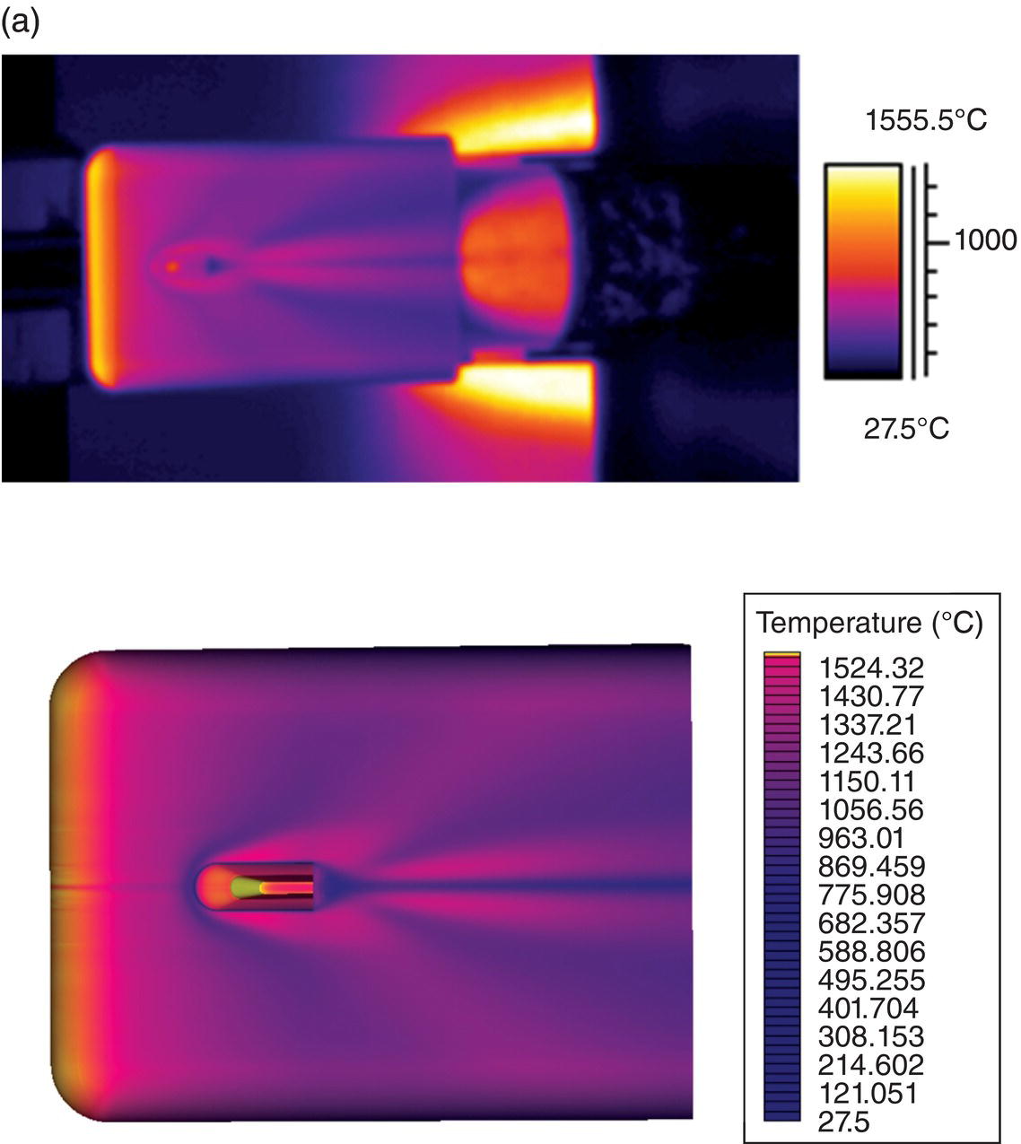
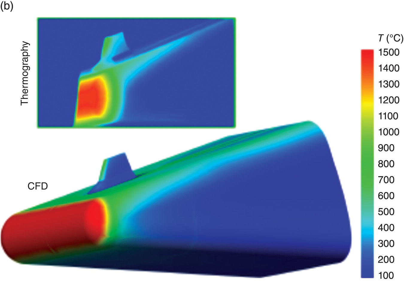
Figure 16.5. IR thermography images recorded during the test and before the holder fracture (t = 32 s) (a) test article in centerline and (b) predicted CFD wall temperature in test conditions.
The first European UHTC payload named EXPERT PL15 was on-ground qualified for the flight on a scientific space capsule by passing all of the demanding mechanical qualification tests—sinusoidal, random, and shock—based on increased test requirements and levels with respect to those expected in the real flight. The same qualification model was tested in the “Scirocco” PWT and the winglet performed as expected, matching CFD predictions until the failure of the model holder. PL15 has also proven that a small UHTC component can survive the foreseen conservative ground qualification tests, if great attention is used in the design of the mechanical interface with metallic structures of the capsule.
16.5 In-Fling Testing of the Capsule “SHARK”
SHARK is a small capsule (Fig. 16.6) designed and realized at CIRA under ESA contract and mounted on the European sounding rocket MAXUS 8 launched on March 26, 2010, from the Swedish space base ESRANGE, near Kiruna, in the far north of the country. Ninety seconds after launch and at 192 km of altitude, SHARK was released when the vehicle was flying at 3 km/s with an 88° flight path angle. The ballistic flight reached over 700 km altitude. Data acquisition was performed with an onboard computer, and the survival of the data in the memory unit was successful due to the design of the hull that protected the internal systems during all flight phases. The system was able to acquire data from 15 thermocouples and 16 analogical channels. Each temperature channel was connected to type-K thermocouple: three were installed inside the UHTC tip, some in the fore region close to the external surface aiming to measure the effect of the aerothermal heating, and some inside the vehicle to evaluate the effects of heating on the internal systems.
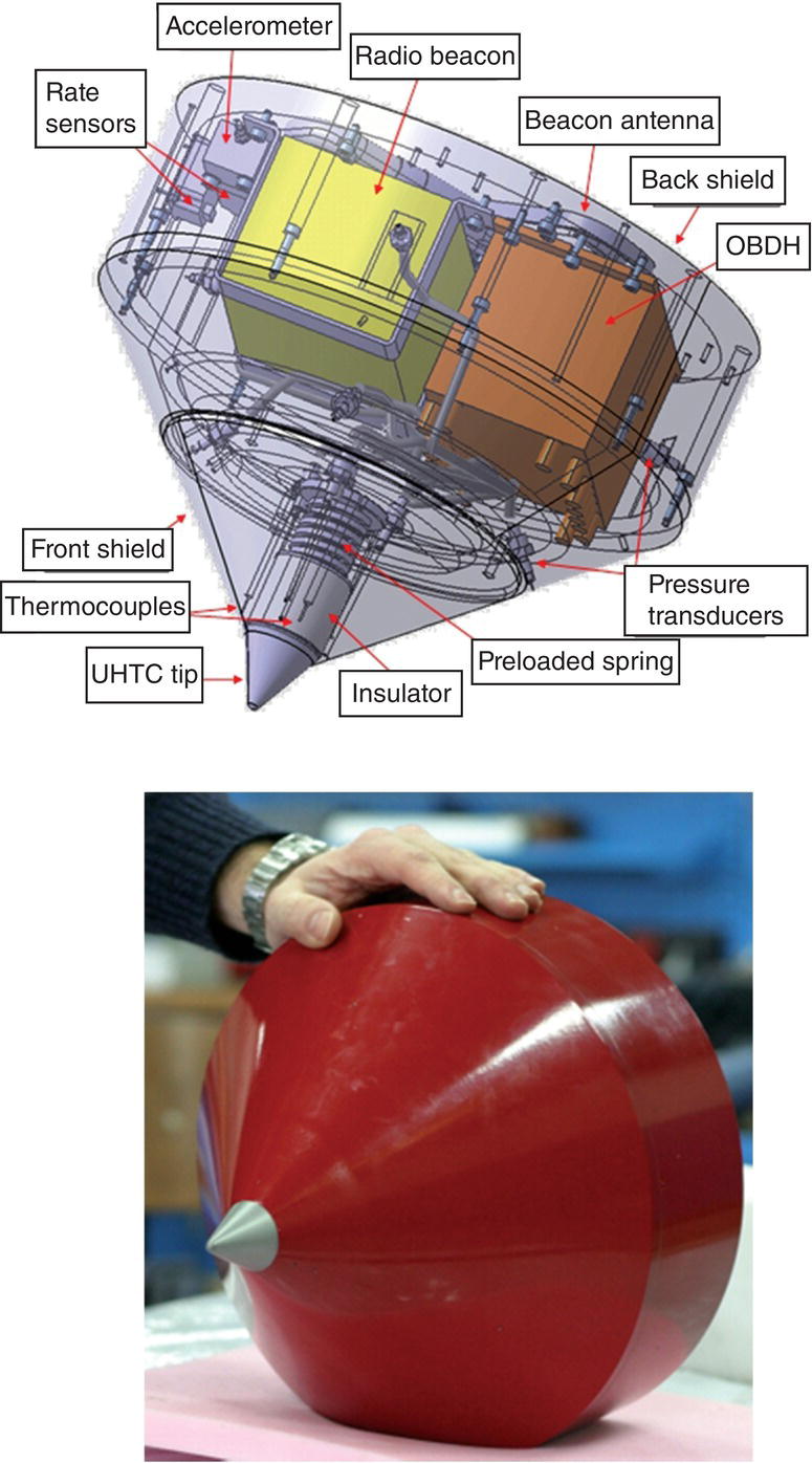
Figure 16.6. 3D model and image of SHARK wherein the gray UHTC tip is visible.
The accuracy of the predicted trajectory was improved by utilizing a landing point. The retrieval of the capsule on July 1, 2010, was carried out through a satellite emergency locator system, operating at 406 MHz. The metallic structure was found in good condition while the UHTC tip was broken into four parts, of which only three were recovered. The paint on the front stainless steel shield was totally removed by the aerodynamic heating, while it was intact on the backside, proving that the reentry attitude was nominal (i.e., it did not tumble).
Post-flight analysis showed that the UHTC tip ruptured during flight. The thermocouple inserted in the tip measured an abrupt temperature increment and then the signal was lost. At the same time, pressure transducers just downstream the UHTC tips measured a pressure variation, due to the different aerodynamic characteristics of the capsule after fracture of the tip. The mechanical interface was designed to crush inside the capsule allowing part of ceramic tip to survive the impact and offering the possibility of post-flight analyses on the UHTC.
Accelerometers sensed the reduction of the drag coefficient that occurred during the transition from the supersonic to the subsonic regime. During the reentry phase, the UHTC tip was exposed to about 9 MW/m2 heat flux and the whole capsule sustained more than 40 g deceleration. The fracture of UHTC tip was triggered by a small defect introduced during machining of the component or during the last ground tests. On the basis of the recovered UHTC parts, extensive analyses of the mechanism of failure and its possible causes were performed. Two kinds of fractures were identified: the main one caused the loss of extreme tip and the secondary one resulted in a division of the recovered ceramic piece into three separated fragments. Both fractures seem to have occurred at the bottom hole, manufactured by EDM, in which the thermocouples were located. In Figure 16.7, the fracture surface of the nose tip with all fractographic findings and the hole for thermocouples are shown.
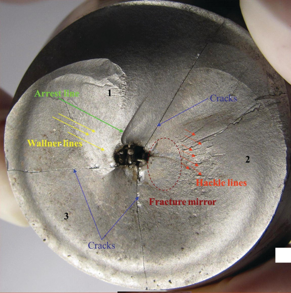
Figure 16.7. Fracture surface of SHARK Nose tip wherein the three separated fragments are also indicated.
16.6 Future Work
The most CIRA research activities on UHTCs were focused on increasing fracture resistance. This goal will be achieved by employing ZrB2-based composites reinforced by discontinuous SiC whiskers or SiC fibers. Starting from laboratory scale, addition of up to 15 vol% fibers to ZrB2 is being studied to evaluate the impacts on sintering process, mechanical properties, and oxidation resistance. Interesting preliminary results drove CIRA to use reinforced ZrB2-SiC chopped fibers composites in the manufacturing of subsequent prototypes and, following the experience gained within the ESA project EXPERT, CIRA has designed, manufactured, and installed two UHTC winglets as passenger payload onto a free-flying scramjet (SCRAMSPACE), a project led by the University of Queensland (Australia), which flew in September 2013.
In parallel, CIRA is also developing and improving the features and the capabilities of UHTC coatings produced by plasma spray. Coatings are deposited on metals using metallic interlayers with the aim to permit use of metal alloys in the most severe thermodynamic conditions and at higher temperatures.
References
- 1. Pavlosky JE, St. Leger LG. Apollo experience report—thermal protection subsystem. NASA technical note TN D-7564 January 1974. Washington (DC): National Aeronautics and Space Administration; 1974.
- 2. Sutton GW. The initial development of ablation heat protection, an historical perspective. J Spacecraft Rockets 1982;19:3–11.
- 3. Schneider PJ, Dolton TA, Reed GW. Mechanical erosion of charring ablators in ground-test and re-entry environments. AIAA J 1968;6:64–72.
- 4. Laux T, Ullmann T, Auweter-Kurtz M, Hald H, Kurz A. Investigation of thermal protection materials along an X-38 re-entry trajectory by plasma wind tunnel simulations. Proceedings of the 2nd International Symposium on Atmospheric Reentry Vehicles and Systems; March 26–29, 2001; Arcachon, France; 2001, AAAF, paper 1–9.
- 5. Glass DE. Ceramic Matrix Composite (CMC) Thermal Protection Systems (TPS) and hot structures for hypersonic vehicles. Proceedings of the 15th Space Planes and Hypersonic Systems and Technologies Conference; April 28–May 1, 2008; Dayton (OH); 2008, AIAA-2008-2682.
- 6. Paul A, Jayaseelan DD, Venugopal S, Zapata-Solvas E, Binner J, Vaidhyananthan B, Heaton A, Brown P, Lee WE. UHTC composites for hypersonic applications. Am Ceram Soc Bull 2012;91:22–28.
- 7. Squire T, Marschall J. Material property requirements for analysis and design of UHTC components in hypersonic applications. J Eur Ceram Soc 2010;30:2239–2251.
- 8. Ushakov SV, Navrotsky A. Experimental approaches to the thermodynamics of ceramics above 1500°C. J Am Ceram Soc 2012;95:1463–1482.
- 9. Johnson SM, Gasch MJ, Squire TH, Lawson JW. Ultra high temperature ceramics: issues and prospects. In: Krenkel W, Lamon J. 7th International Conference on High Temperature Ceramic Matrix Composites (HT- CMC 7); September 20-22, 2010; Bayreuth, Germany. p 818–831.
- 10. Justin JF, Jankowiak A. Ultra high temperature ceramics: densification, properties and thermal stability. Onera J Aerosp Lab 2011;3:1–11.
- 11. Russo G, Marino G. The USV program & UHTC development. Proceedings of the 4th European Workshop on Thermal Protection Systems for Space Vehicles; November 26–29, 2002; Palermo, Italy. Paris: European Space Agency; 2002, paper 157–163.
- 12. Savino R, De Stefano Fumo M, Paterna D, Serpico M. Aerothermodynamic study of UHTC-based thermal protection systems. Aerosp Sci Technol 2005;9:151–160.
- 13. Scatteia L, Del Vecchio A, De Filippis F., Marino G, Savino R. PRORA-USV SHS: Development of sharp hot structures based on ultrahigh temperature metal diborides current status. Proceedings of the 56th International Astronautical Congress; November 17–21, 2005; Fukuoka, Japan. West Chester (OH): Curran Associates Inc; 2005, paper IAC-05-C2.3.05.
- 14. Del Vecchio A, Di Clemente M, Ferraiuolo M, Gardi R, Marino G, Rufolo G, Scatteia L. Sharp hot structures project current status. Proceedings of the 57th International Astronautical Congress; Valencia, Spain; October 2–6, 2006, paper IAC-06-C2.4.05.
- 15. Bartuli C, Valente T, Tului M. Plasma spray deposition and high temperature characterization of ZrB2-SiC protective coatings. Surf Coating Technol 2002;155:260–273.
- 16. Tului M, Ruffini F, Arezzo F, Lasisz S, Znamirowski Z, Pawlowski L. Some properties of atmospheric air and inert gas high-pressure plasma sprayed ZrB2 coatings. Surf Coating Technol 2002;151–152:483–489.
- 17. Tului M, Marino G, Valente T. Plasma spray deposition of ultra high temperature ceramics. Surf Coating Technol 2006;201:2103–2108.
- 18. Tripp WC, Davis HH, Graham HC. Effect of SiC addition on the oxidation of ZrB2. Am Ceram Soc Bull 1973;52:612–616.
- 19. Monteverde F, Guicciardi S, Bellosi A. Advances in microstructure and mechanical properties of zirconium diboride based ceramics. Mater Sci Eng 2003;346:310–319.
- 20. Chamberlain A, Fahrenholtz W, Hilmas G. High-strength zirconium diboride-based ceramics. J Am Ceram Soc 2004;87:1170–1172.
- 21. Monteverde F. Beneficial effects of an ultra-fine α-SiC incorporation on the sinterability and mechanical properties of ZrB2. Appl Phys A Mater Sci Process 2006;82:329–337.
- 22. Kuriakose AK, Magrave JL. The oxidation kinetics of zirconium diboride and zirconium carbide at high temperatures. J Electrochem Soc 1964;111:827–831.
- 23. Tripp WC, Graham HC. Thermogravimetric study of the oxidation of ZrB2 in the temperature range of 800°C to 1500°C. J Electrochem Soc 1971;118:1195–1199.
- 24. Opeka MM, Talmy IG, Wuchina EJ, Zaykoski JA, Causey SJ. Mechanical, thermal, and oxidation properties of refractory hafnium and zirconium compounds. J Eur Ceram Soc 1999;19:2405–2414.
- 25. Ban'kovskaya IB, Zhabrev VA. Kinetic analysis of the heat resistance of ZrB2–SiC composites. Glass Phys Chem 2005;31:482–488.
- 26. Chamberlain A, Fahrenholtz W, Hilmas G, Ellerby D. Oxidation of ZrB2-SiC ceramics under atmospheric and reentry conditions. Refract Appl Trans 2005;1:1–8.
- 27. Fahrenholtz WG. The ZrB2 volatility diagram. J Am Ceram Soc 2005;88:3509–3512.
- 28. Fahrenholtz G, Hilmas GE, Talmy IG, Zaykoski JA. Refractory diborides of zirconium and hafnium. J Am Ceram Soc 2007;90:1347–1364.
- 29. Fahrenholtz WG. Thermodynamic analysis of ZrB2-SiC oxidation: formation of a SiC-depleted region. J Am Ceram Soc 2007;90:143–148.
- 30. Levine SR, Opila EJ, Halbig MC, Kiser JD, Singh M, Salem JA. Evaluation of ultra-high temperature ceramics for aeropropulsion use. J Eur Ceram Soc 2002;22:2757–2767.
- 31. Fahrenholtz WG, Hilmas GE, Chamberlain AL, Zimmermann JW. Processing and characterization of ZrB2-based ultra-high temperature monolithic and fibrous monolithic ceramics. J Mater Sci 2004;39:5951–5957.
- 32. Gasch M, Ellerby D, Irby E, Beckman S, Gusman M, Johnson S. Processing, properties and arc jet oxidation of hafnium diboride/silicon carbide ultra high temperature ceramics. J Mater Sci 2004;39:5925–5937.
- 33. Opeka MM, Talmy IG, Zaykoski JA. Oxidation-based materials selection for 2000°C + hypersonic aerosurfaces: theoretical considerations and historical experience. J Mater Sci 2004;39:5887–5904.
- 34. Opila E, Levine S, Lorincz J. Oxidation of ZrB2- and HfB2-based ultra-high temperature ceramics: effect of Ta additions. J Mater Sci 2004;39:5969–5977.
- 35. Monteverde F, Bollosi A. The resistance to oxidation of an HfB2–SiC composite. J Eur Ceram Soc 2005;25:1025–1031.
- 36. Rezaire A, Fahrenholtz WG, Hilmas GE. Evolution of structure during the oxidation of zirconium diboride–silicon carbide in air up to 1500°C. J Eur Ceram Soc 2007;27:2495–2501.
- 37. Rezaire A, Fahrenholtz WG, Hilmas GE. Oxidation of zirconium diboride silicon carbide at 1500°C at a low partial pressure of oxygen. J Am Ceram Soc 2006;89:3240–3245.
- 38. Han J, Hu P, Zhang X, Meng S, Han W. Oxidation-resistant ZrB2-SiC composites at 2200°C. Compos Sci Technol 2008;68:799–806.
- 39. Zhang X, Hu P, Han J, Meng S. Ablation behaviour of ZrB2–SiC ultra high temperature ceramics under simulated atmospheric re-entry conditions. Compos Sci Technol 2008;68:1718–1726.
- 40. Carney CM, Mogilvesky P, Parthasarathy TA. Oxidation behaviour of zirconium diboride silicon carbide produced by the spark plasma sintering method. J Am Ceram Soc 2009;92:2046–2052.
- 41. Hu P, Goulin W, Wang Z. Oxidation mechanism and resistance of ZrB2-SiC composites. Corros Sci 2009;51:2724–2732.
- 42. Karlsdottir SN, Halloran JW. Oxidation of ZrB2-SiC: influence of SiC content on solid and liquid oxide phase formation. J Am Ceram Soc 2009;92:481–486.
- 43. Eakins E, Jayaseelan DD, Lee WD. Toward oxidation-resistant ZrB2-SiC ultra high temperature ceramics. Metall Mater Trans A 2010;42:878–887.
- 44. Scatteia L, Alfano D, Monteverde F, Sans J-L, Balat-Pichelin M. Effect of the machining method on the catalycity and emissivity of ZrB2 and ZrB2–HfB2-based ceramics. J Am Ceram Soc 2008;91:1461–1468.
- 45. Monteverde F, Bellosi A, Scatteia L. Processing and properties of ultra-high temperature ceramics for space applications. Mater Sci Eng A 2008;485:415–421.
- 46. Scatteia L, Borrelli R, Cosentino G, Bêche E, Sans J-L, Balat-Pichelin M. Catalytic and radiative behaviors of ZrB2–SiC ultra high temperature ceramic composites. J Spacecraft Rockets 2006;43:1004–1012.
- 47. Alfano D, Scatteia L, Monteverde F, Bêche E, Balat-Pichelin M. Microstructural characterization of ZrB2–SiC based UHTC tested in the MESOX plasma facility. J Eur Ceram Soc 2010;30:2345–2355.
- 48. Charpentier L, Dawi K, Eck J, Pierrat B, Sans J-L, Balat-Pichelin M. Concentrated solar energy to study high temperature materials for space and energy. J Sol Energy Eng 2011;133:031005.
- 49. Eck J, Sans J-L, Balat-Pichelin M. Experimental study of carbon materials behavior under high temperature and VUV radiation: application to Solar Probe + heat shield. Appl Surf Sci 2011;257:3196–3204.
- 50. Balat-Pichelin M, Badie J-M, Berjoan R, Boubert P. Recombination coefficient of atomic oxygen on ceramic materials under earth re-entry conditions by optical emission spectroscopy. Chem Phys 2003;291:181–194.
- 51. Balat-Pichelin M, Vesel A. Neutral oxygen atom density in the MESOX air plasma solar furnace facility. Chem Phys 2006;327:112–118.
- 52. Reibaldi G, Gavira J, Ratti F, de Mey S, Muylaert J-M, Provera R, Massobrio F. EXPERT: the Esa eExperimental re-entry test-bed programme. Proceedings of the 59th International Astronautical Congress; Glasgow, Scotland; September 29 to October 3, 2008, IAC-08.D2.6.3.
- 53. BS EN 843-1:2006 Advanced technical ceramics. Mechanical properties of monolithic ceramics at room temperature. Determination of flexural strength. BS EN 820-1:2002 Advanced technical ceramics. Methods of testing monolithic ceramics. Thermo-mechanical properties. Determination of flexural strength at elevated temperatures.
- 54. Zhang XH, Hu P, Han J, Xu L, Meng S. The addition of lanthanum hexaboride to zirconium diboride for improved oxidation resistance. Scripta Mater 2007;57:1036–1039.
- 55. Hu P, Zhang XG, Han JC, Luo XG, Du SY. Effect of various additives on the oxidation behavior of ZrB2-based ultra high temperature ceramics at 1800°C. J Am Ceram Soc 2010;93:345–349.
- 56. Jayaseelan DD, Zapata-Solvas E, Brown P, Lee WE. In situ formation of oxidation resistant refractory coatings on SiC-reinforced ZrB2 ultra high temperature ceramics. J Am Ceram Soc 2012;95:1247–1254.
- 57. Subramanian MA, Aravamudan G, Subba Rao GV. Oxide pyrochlores—a review. Prog Solid State Chem 1983;15:55–143.
- 58. Cao XQ, Vassen R, Stöver D. Ceramic materials for thermal barrier coatings. J Eur Ceram Soc 2004;24:1–10.
- 59. Monteverde F, Alfano D, Savino R. Effects of LaB6 addition on arc-jet convectively heated SiC-containing ZrB2-based UHTC in high enthalpy supersonic airflows. Corros Sci 2013;75:443–453.
- 60. Borrelli R, Riccio A, Tescione D, Gardi R, Marino G. Numerical/experimental correlation of a plasma wind tunnel test on a UHTC-made nose cap of reentry vehicle. J Aerospace Eng 2010;23:309–316.