Chapter 2. Switching
This chapter of the book contains Experiments 6 through 11, which explore the seemingly simple topic of switching—by which I mean not just manual control, but using one flow of electricity to switch, or control, another. It’s such an important principle, no digital device can exist without it.
Today, switching is mostly done with transistors. I will deal with them in detail, but before that I’ll back up and illustrate the concept by introducing you to relays, which are easier to understand, because you can see what’s going on inside them. And before I get to relays, I’ll show how manually activated switches can demonstrate some of the concepts that will follow. So, the sequence will be switches—relays—transistors.
Also in this chapter, I’ll deal with capacitance, because capacitance is almost as fundamental as resistance in electronic circuits.
Necessary Items for Chapter Two
As before, when buying tools and equipment, see “Buying Tools and Equipment” for a shopping list. If you want kits containing components and supplies, see “Kits”. If you prefer to buy your own components and supplies from online sources, see “Components”.
Essential: Small Screwdrivers
A set such as the one made by Stanley (part number 66-052) is shown in Figure 2-1. Screwdrivers that you may already have in your home will be too big for most of the little screws that you find on components.
You can buy cheaper screwdriver sets that look very similar to the one in Figure 2-1, but I think the quality of steel is better in name-brand screwdrivers.
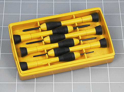
Figure 2-1. Miniature screwdrivers, with both flat blades and Phillips blades. The white lines are spaced at intervals of 1”.
Essential: Small Long-Nosed Pliers
The type of long-nosed pliers that you need are no more than five inches from end to end. You’ll be using them to bend wire precisely, or to pick up small parts where a finger and thumb are too big and clumsy. For these kinds of operations I don’t think you benefit much from spending extra money on high-quality tools, so feel free to buy the cheapest. An example is shown in Figure 2-2. These have spring-loaded handles, which some people don’t like, but you can pull out the springs—if you have a second pair of pliers to do so.
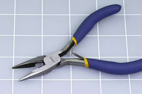
Figure 2-2. Appropriate pliers for electronics work should be no more than 5” long.
Optional: Sharp-Nosed Pliers
These are like small long-nosed pliers, but with very precise, pointed jaws. I like them for accessing tightly packed components on a breadboard. Your best source is a website or store that specializes in craft work such as beading. Be careful, however, that you don’t buy beading pliers that have rounded noses for making loops in wire. For our purposes, the inner surfaces of the jaws should be flat, as shown in Figure 2-3.

Figure 2-3. Sharp-nosed pliers enable very precise work on a small scale.
Essential: Wire Cutters
Pliers usually have cutting edges near the joint, which you can use for chopping wire. Often, however, a piece of wire will be attached to something else, and you won’t be able to reach it with your pliers. You really need wire cutters such as those shown in Figure 2-4. They should be no longer than five inches. So long as you use them to cut thin, soft copper wire, they do not have to be of high quality.
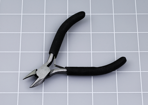
Figure 2-4. Wire cutters should be no more than 5” long.
Optional: Flush Cutters
Flush cutters, shown in Figure 2-5, are similar to wire cutters, and do the same job, but they are thinner, smaller, and better able to get into small spaces. However, they are less robust. Whether you use them or wire cutters is a matter of personal preference. Personally I like wire cutters.
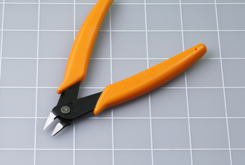
Figure 2-5. Flush cutters can get into smaller spaces than wire cutters.
Essential: Wire Strippers
Wire of the type that you will be using has a coating of plastic insulation. Wire strippers are specifically designed to remove a short section of insulation to expose the conductor inside it. Macho hobbyists may claim that they don’t need any tool to do this job, but I have two corners missing from the insides of my front teeth to testify that this is a really bad idea (see Figure 2-6).

Figure 2-6. In a hurry? Can’t find your wire strippers? The temptation is obvious, but not a good idea.
Another option is to use wire cutters, as shown in Figure 2-7. You hold the wire in one hand, close the jaws of the cutters gently with the other hand, and lever your two hands apart. However, this is a skill that requires practice. Sometimes the cutters slip off without doing anything, or they may cut the wire instead of stripping it.
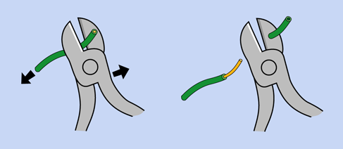
Figure 2-7. How to use wire cutters to strip insulation. Wire strippers are easier to use.
For a few extra dollars, a pair of wire strippers makes the job so much easier.
The first edition of this book included an option to buy so-called automatic wire strippers, which can be used with only one hand. Unfortunately they are significantly more expensive than other types of wire strippers, and many brands don’t work well with the 22-gauge hookup wire required for all the circuits in this book. Therefore, I don’t recommend them anymore.
The type of tool shown in Figure 2-8 is available from many manufacturers. Some brands have angled handles, some have straight handles, and some have curved handles. I don’t think it matters. They all work the same way: you insert the wire in a hole of appropriate size, close the jaws, and pull away the insulation.

Figure 2-8. The recommended wire strippers are designed for 20-gauge to 30-gauge wire.
You do have to be careful, though, that they are suitable for the right size of wire.
Wire gauge is a measure of the thickness of a conductor. A higher number indicates a thinner wire. As it happens, 20-gauge wire is slightly too thick for our purposes, while 24-gauge wire is slightly too thin. The optimal thickness is 22 gauge, and you will have a much easier time if you buy a tool that is calibrated for that specific size. As you can see in Figure 2-8, a range from 20 gauge to 30 gauge includes a little hole for 22 gauge. This is the right tool for the job.
Essential: Breadboards
Breadboards are not required until Experiment 8, but I will provide a brief introduction here. The breadboard is a little plastic slab perforated with holes at intervals of 0.1”. You push components and wires into the holes. Hidden beneath the plastic are conductors that make connections along the rows of holes.
A breadboard allows components to be connected together more neatly than with the test leads that you have used so far, and more easily (and reversibly) than if you join them with solder.
-
A breadboard is properly known as a solderless breadboard and is sometimes referred to as a prototyping board.
The brand or source is not important, but you should be careful to buy the same configuration that I have used throughout this book. You have three options, only one of which is correct:
Breadboard Option 1: The Mini, shown in Figure 2-9. Often sold as being “suitable for Arduino,” it doesn’t have enough holes in it for our purposes, so, don’t buy one of those.
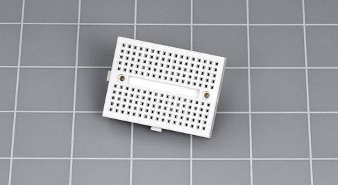
Figure 2-9. A mini-board is not big enough for many of the projects in this book.
Breadboard Option 2: Single-Bus, shown in Figure 2-10. The term “bus” refers to a long column of holes alongside the short, numbered rows of holes. There is a single bus on each side, outlined in red in the photograph. This is the kind of board that you want. Check a photograph of the product that you are buying, to make sure. Also, note that it should have 60 rows of holes and 700 connection points (also known as tie points). If you are buying your own, search Amazon or eBay for:
solderless breadboard 700
If you prefer, you can use a dual-bus breadboard and just ignore the extra holes.
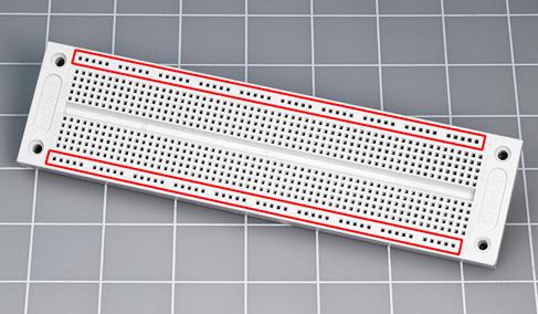
Figure 2-10. A single-bus breadboard has a single long row of holes along each side.
Breadboard Option 3: Dual Bus, shown in Figure 2-11. This has two long rows of holes on each side, which are the dual buses, outlined in red in the photograph. I used this type of board in the first edition of this book, because it can be more convenient. Then I saw how it encouraged wiring errors when people used it for the first time, so I don’t recommend dual-bus breadboards anymore.
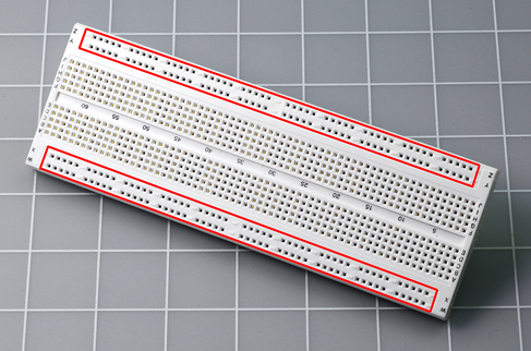
Figure 2-11. A dual-bus breadboard has two pairs of long rows of holes, outlined in red in this photograph. This style of board is no longer recommended.
Now that I’ve established the type of board that I recommend, how many of them do you need? I used to say, “Only one,” bearing in mind that they are reusable, but their price has been driven down to the point where I think you should consider buying two or three. This way, you can prototype new circuits without having to disassemble old ones first.
Supplies
If you want to buy a kit containing components and supplies, see “Kits”. When buying your own supplies, see “Supplies”.
Essential: Hookup Wire
The type of wire you need for making connections on a breadboard is often called hookup wire although it can be found, sometimes, under the general category of bulk wire. Either way, it must have a solid core (not stranded), and must be 22 gauge in size.
Often it is sold in 25-foot and 100-foot lengths on plastic spools, as shown in Figure 2-12.
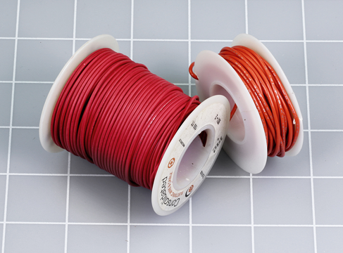
Figure 2-12. Hookup wire is available on spools holding 25 feet and 100 feet, shown here.
Wire is cheaper, per foot, if you buy a 100-foot spool, but I suggest you should buy smaller quantities in at least three different colors of insulation. The reason is that wire colors are helpful when you are trying to find an error in a circuit that you have built. Red and blue can be used for connections with positive and negative power, and one other color for other connections.
When the insulation is stripped away, it reveals a solid conductor, as shown in Figure 2-13. Compare this with stranded wire, shown in Figure 2-14. Stranded wire does have some uses, which I will talk about in a moment, but if you try to push it into holes in a breadboard, you are likely to become frustrated quite quickly. You really need solid wire.
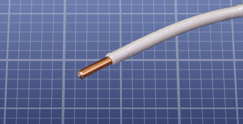
Figure 2-13. Inside the plastic insulation, there should be a single conductor of solid wire.
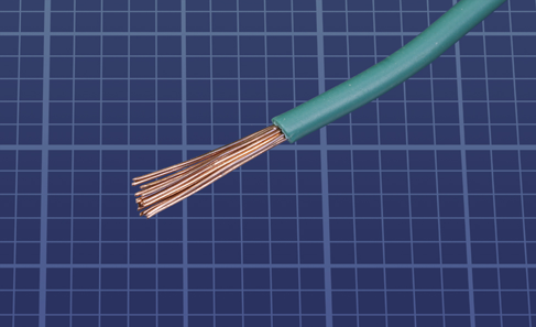
Figure 2-14. For specific purposes (described in the text) stranded wire can be a useful option.
Just as I emphasized the need for wire strippers that are specifically designed for 22-gauge wire, I will now emphasize that the wire should be 22-gauge, not 20-gauge, and not 24-gauge. You will find that the 24-gauge wire doesn’t fit tightly in a breadboard, and may not make a reliable connection, while 20-gauge wire is just a little too thick, so that when you try to push it in, it can bend instead of sliding into place—and if you do manage to insert it, pulling it out can be difficult.
Some copper wire has a silver-colored coating, when you strip the insulation away. This is said to be “tinned.” Other wire is plain copper, and I don’t have any opinion about which type is better.
How much will you need? For assembling the circuits in this book, 25 feet of each color will be more than enough. However, Experiments 26, 28, and 29 require you to make coils of wire, to explore the relationship between electricity and magnetism, and to build your own crystal-set radio. If you want to pursue these projects (which I think are worthwhile), you’ll need 200 feet of wire. This is your choice, as none of the kits for this book contains that much wire. See “Supplies” for information about buying wire.
Jumpers
If you cut a section of wire, strip at least 1/4” but no more than 3/8” insulation from each end, bend the ends down, and push them into holes in a breadboard, you have just made a jumper, which creates a connection by jumping across some intervening holes in the board. Jumpers of this type result in a neat circuit where you can find errors relatively easily.
The trouble is, stripping insulation and making right-angle bends is tedious, even with the right tools for the job. Therefore you may be inclined to purchase precut wire which has been made into jumpers for you. An assortment looks like the one shown in Figure 2-15. For guidance about finding a selection like this, see “Supplies”.
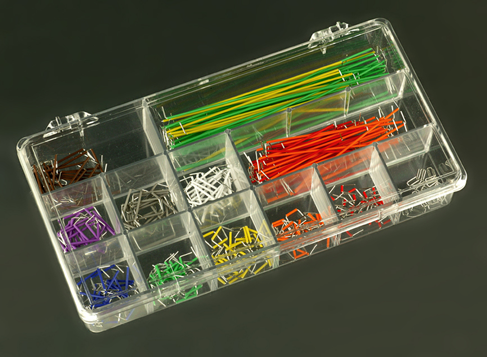
Figure 2-15. An assortment of precut wire, stripped and bent for use in a breadboard.
I used to use precut wire myself, but gave up on it because the wire segments are colored according to their length rather than their function. Red wires are all 0.2” long, yellow wires are all 0.3” long, and so on.
I want wires to be colored according to what they do in a circuit. Thus, red wires should always be connected to the positive side of the power supply, regardless of how long they are.
The only way to achieve this is to cut your own, which is what I do. You are welcome to use the precut wire if you so choose—but in addition to being confusingly colored, it costs more.
There is one more issue I have to clarify regarding jumpers. Many people like to use a different type of jumper wire that has a little plug at each end, just the right size to push into holes in a breadboard. These “plugged jumpers” are sold in bundles, and are probably the first thing you will find if you search for jumper wires online.
Because they are flexible, and they are usually about three inches long, you can use them to make almost any connection you are likely to need on a breadboarded circuit. They are reusable, and appear to be the simplest, quickest, cheapest option.
So far, so good; but if you make a mistake, you are going to have a problem finding it. Figure 2-16 shows a small circuit for an application outside of this book, using flexible jumpers that have plugs on each end. Figure 2-17 shows exactly the same circuit with hand-cut jumper connections using solid-core 22-gauge wire. Each of these circuits contains one wiring error. On the one using hand-cut wire, I can see it within a few seconds. On the one using flexible jumpers, I would have to dig around for quite a while, probably using a meter to search for the fault.
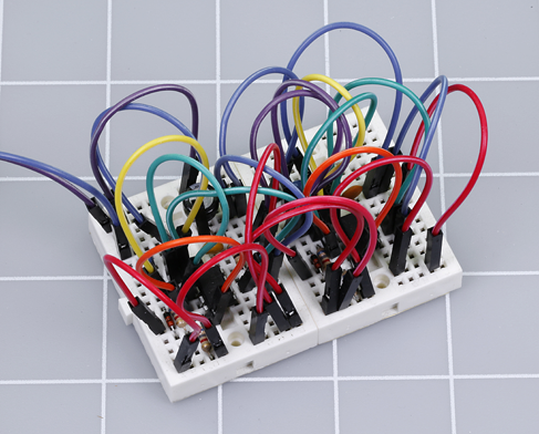
Figure 2-16. A circuit on two mini-breadboards using flexible jumper wires with a plug at each end.
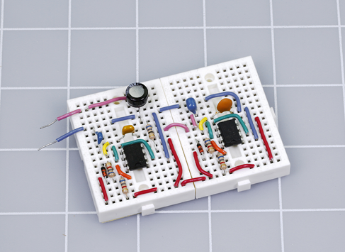
Figure 2-17. The same circuit as in the previous figure, using hand-cut solid jumper wires.
To make matters worse, the plugs on flexible jumpers are sometimes defective, and may contain loose connections. This can make fault-tracing almost impossible. Therefore:
-
I don’t recommend flexible jumpers that have plugs on each end.
Optional: Stranded Wire
Getting back to stranded hookup wire, it does have one advantage. It is much more flexible than solid wire, which is useful if you are running it out from a circuit board to a switch or a potentiometer. Flexibility can be essential if the wire is making a connection with an object that moves or vibrates.
While flexible wire is not essential for any of the projects in this book, 25 feet of 22-gauge stranded will come in handy occasionally. If you buy some, I suggest you choose a color that is different from your colors of solid wire, so that you won’t confuse it with them.
Components
Again I must remind you that component kits for the projects in this book are available. See “Kits”. If you prefer to buy your own components from online sources, see “Components”.
Essential: Toggle Switch
A full-size toggle switch is an old-fashioned device, but useful for your switching experiments. You will need two. They should be described as SPDT, meaning single-pole double-throw. I’ll explain this in detail a little later. Double-pole double-throw, described as DPDT, can also be used, but may cost slightly more.
A toggle switch with screw terminals will reduce the inconvenience of attaching it to hookup wire, but other types of terminals are acceptable.
A typical full-size toggle switch is shown in Figure 2-18. E-Switch ST16DD00 is an example, but cheaper generic alternatives can be found on eBay.
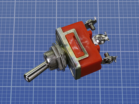
Figure 2-18. A full-size toggle switch.
Essential: Tactile Switch
Confusingly, a tactile switch is not what you would think of as a switch. It is a very tiny pushbutton. If you plug it into your breadboard, it provides a convenient way for a circuit to receive user input.
The most commonly used tactile switches have four little legs to push into a board, and can be annoying, because the legs often don’t engage properly. The component is liable to spring out like a baby grasshopper at unexpected moments. I suggest you use a tactile switch with two pins spaced 0.2” apart. The Alps SKRGAFD-010 will be used in projects throughout this book, and is shown in Figure 2-19. Any other tactile switch with two pins spaced 0.2” apart can be substituted, such as the Panasonic EVQ-11 series.
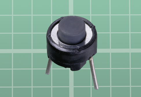
Figure 2-19. The recommended tactile switch for breadboarded projects in this book.
Essential: Relay
Because pin functions are not standardized among manufacturers, you have to be cautious about making substitutions when you buy a relay. I am recommending the Omron G5V-2-H1-DC9, shown in Figure 2-20, which should minimize confusion, because it has its pin functions printed on it.
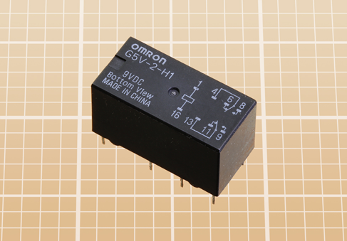
Figure 2-20. The relay recommended for use with this book.
Omron is a large manufacturer of relays, so I have some hope that the one I am recommending will be around for a while. You may also use the Axicom V23105-A5006-A201 or the Fujitsu RY-9W-K. All of them are are 9VDC DPDT relays, with pins spaced as shown on the left side of Figure 2-21. If the spacing is shown in millimeters, 5mm or 5.08mm are acceptable substitutes for 0.2”, and 7.5mm or 7.62mm can substitute for 0.3”.
If a diagram is printed on the relay, it should look like the one on the right side of Figure 2-21. Datasheets for relays almost always contain this information. You can use relays with different pin functions, but they will cause you some inconvenience, because they won’t match the schematics that I will be providing.
The relays I have recommended are high-sensitivity type, meaning that they consume less current. You can substitute others, but they will draw more current. Whichever type of relay you use, it must have the same 9VDC coil voltage and pin spacing.
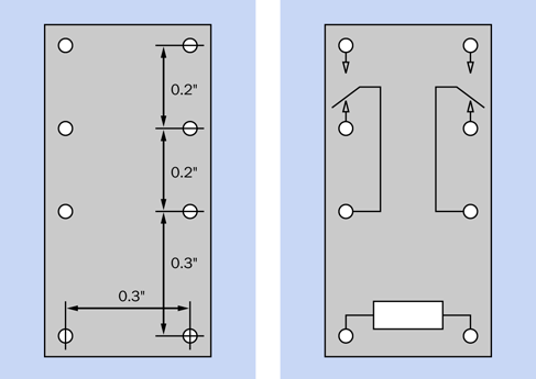
Figure 2-21. Pin spacing and internal connections in a relay should be as shown.
One thing to watch out for, when buying relays, is their polarity, meaning a requirement to apply current in one specified direction, because the relay won’t work when current flows through its coil in the other direction. I have recommended relays that do not require polarity. Many Panasonic relays do, so read the datasheet carefully before buying one of them.
Lastly, any relay that you buy must be of the nonlatching type.
If this seems confusing and overly technical, you can put off buying the relay until you read Experiment 7, which describes how to use it. You will need two relays to carry out that experiment fully.
Essential: Trimmer Potentiometer
Instead of the big clunky potentiometer that you used in Experiment 4, you’ll be using a trimmer potentiometer, which is smaller, cheaper, and plugs into a breadboard. Examples (with various arbitrary values) are shown in Figure 2-22.
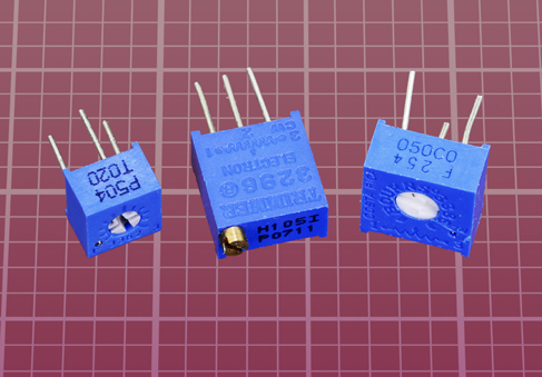
Figure 2-22. Trimmer potentiometers.
The trimmers at left and at right in this photograph are the type that I have chosen to use in this book. They will sit flush with a breadboard when their leads are pushed down into it. The only difference between these two samples is that one is slightly larger than the other. They are also available in variants that stand up at an angle of 90 degrees with the breadboard, but these are less accessible.
The one in the center of the photograph is a multi-turn trimmer, which allows much finer adjustment via a brass screw connected with a worm gear inside the component. This is less convenient, more expensive, and is not necessary for our purposes, as you won’t require that degree of accuracy.
Essential: Transistors
Only one type of transistor is used in this book. The generic part number is 2N2222, but unfortunately, not all 2N2222 transistors are alike.
If you are using a kit, you should have no problems. If you do your own shopping, you absolutely must avoid any part that has P2N preceding the 2222 number. When the P2N2222 was introduced, the manufacturers reversed the pin functions of the 2N2222 that had been standardized for decades. (Why would they do this? I do not know.)
Here’s the rule.
-
Part numbers 2N2222 or PN2222 or PN2222A are okay. PN2222 has become a more common designation than 2N2222, but either will work.
-
Part numbers P2N2222 or P2N2222A are not okay.
The trap is that if you are searching for 2N2222, you will be offered a P2N2222 because the search engine will help you out by showing parts that have extra letters preceding the number. So—shop with care! And if you have a meter that tests transistors, check each one. If the transistor has the traditional pin functions, the meter should tell you that it has an amplification ratio exceeding 200. If you have the wrong type of transistor, your meter will show an error or an amplification value lower than 50.
2N2222 transistors used to be packaged in tiny metal cans. These days, they are almost always packaged in black plastic. Examples of both types are shown in Figure 2-23. Plastic and metal packages both work equally well—so long as the transistor’s part number does not begin with P2N.
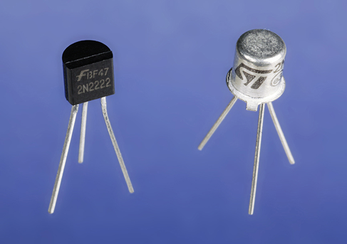
Figure 2-23. Two 2N2222 transistors. Either can be used.
Essential: Capacitors
Capacitors are not quite as cheap as resistors, but still cheap enough for you to consider buying an assortment of small ones in bulk. Capacitor values in the range that we will be using are most often measured in microfarads, abbreviated µF. I’ll explain this in detail when you start using capacitors in your circuits.
For small values, ceramic capacitors are recommended. For larger values, electrolytics are cheaper. For additional guidance about purchasing them, see “Components”. Various capacitors are shown in Figure 2-24. The cylindrical ones are electrolytic, while the others are ceramic.
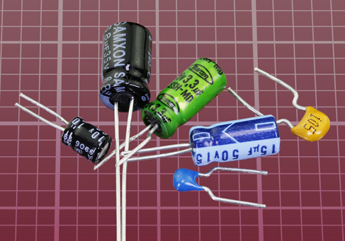
Figure 2-24. A variety of capacitors.
Essential: Resistors
If you are shopping for your own components, I am assuming that you bought a good selection of resistors as I suggested for Experiment 1.
Essential: Loudspeaker
Minimum size for a loudspeaker is 1” diameter, but 2” diameter is good. A 3” diameter is maximum. The impedance should be 8 ohms or higher. When searching for a loudspeaker, bear in mind that some suppliers call them “speakers.” This may cause a search for “loudspeaker” to yield no results.
We will not be dealing with high-fidelity sound, so any cheap loudspeaker will do. A couple of samples are shown in Figure 2-25.
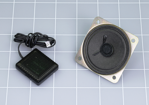
Figure 2-25. Two speakers, one measuring 1” diameter, the other measuring 2”.
And More?
By now you may be thinking that I have specified quite a lot of components. Rest assured that almost everything that I have listed here will be reusable, and you will not need many additional parts for the remaining chapters of the book.
Experiment 6: Very Simple Switching
This experiment will acquaint you with the function of manually operated switches. You may feel that you already know how to use a switch, but when two double-throw switches are combined in a circuit, the subject becomes a little more interesting.
What You Will Need
-
Screwdriver, wire cutters, wire strippers
-
Hookup wire, 22-gauge, no more than 12”
-
9-volt battery (1)
-
Generic LED (1)
-
Toggle switches, SPDT or DPDT (2)
-
470-ohm resistor (1)
-
Test leads with alligator clips at each end (2)
Assemble the parts as shown in Figure 2-26. You’ll need to practice your abilities at wire stripping, here, to bare the ends of the two sections of black wire. To secure them in the screw terminals of the switches, try using your pliers to curl the end of each wire so that it looks like a letter J. Then feed it under the screw from the left, so that the screw will draw in the wire when tightened in a clockwise direction.
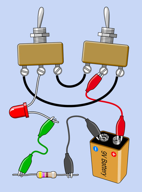
Figure 2-26. Your very first experiment in switch connections.
The long lead on the LED also fits one of the screw terminals. Don’t use the short lead of the LED by mistake. Remember, the long lead must always be more positive than the short lead.
If your switches don’t terminate in screw terminals, you will have to use a couple of alligator test leads instead of the black wires, and one more test lead to connect the LED with the center terminal of the lefthand switch.
After you connect the battery, experiment, flipping the switches. What do you find?
If the LED is on, flipping either of the switches will turn it off. If the LED is off, either of the switches will turn it on. I’ll explain this interesting behavior shortly (see “Introducing Schematics”), but I have to tell you some fundamentals and background information first.
Fundamentals: All About Switches
The toggle in a toggle switch is the part that you flip with your finger. In the type of switch shown in Figure 2-26, flipping the toggle connects the center terminal with one of the terminals on either side of it, as shown in Figure 2-27.
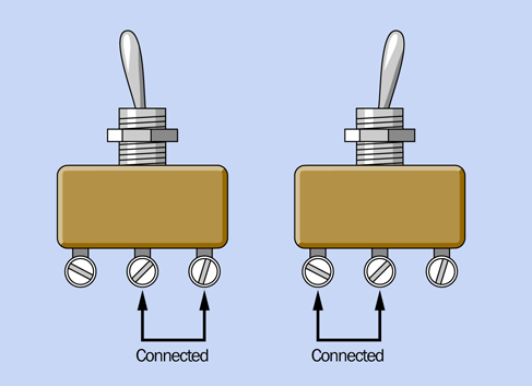
Figure 2-27. Usually, but not absolutely always, toggle switches work like this.
The center terminal is called the pole of the switch. Because you can flip, or throw, this switch to make two possible connections, it is called a double-throw switch, abbreviated DT (or, sometimes, 2T). A single-pole, double-throw switch is abbreviated SPDT (or, sometimes, 1P2T).
Some switches only have two terminals instead of three. They are on/off, meaning that if you throw them in one direction they make a contact, but in the other direction they make no contact at all. Most of the light switches in your house are like this. They are known as single-throw switches. A single-pole, single-throw switch is abbreviated SPST (or, sometimes, 1P1T).
Some switches have two entirely separate poles, so you can make two separate connections simultaneously when you flip the switch. These are called double-pole switches, abbreviated DP (or, sometimes, 2P). Check Figure 2-28, Figure 2-29, and Figure 2-30 for photographs of old-fashioned “knife” switches, which are still used sometimes to teach electronics to kids in school. You wouldn’t use a switch like this for any practical purpose, but they illustrate very clearly the differences between SPST, SPDT, and DPST connections.
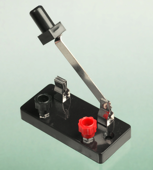
Figure 2-28. Manufactured for educational use, this is a single-pole, single-throw (SPST) switch.
The only place you’re likely to see a knife switch being used for serious purposes is in a horror movie. In Figure 2-31, a mad scientist is powering up his experiment with a single-pole, double-throw knife switch, conveniently mounted on the wall of his basement laboratory.
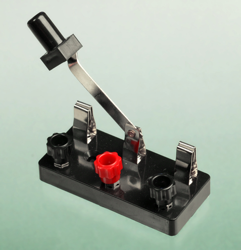
Figure 2-29. A single-pole, double-throw (SPDT) switch connects one pole with a choice of contacts.
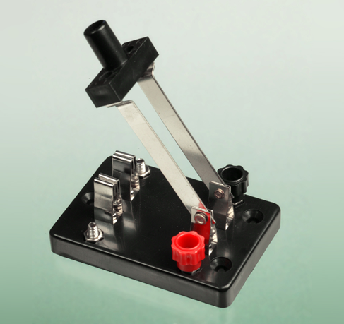
Figure 2-30. A double-pole, single-throw (DPST) switch has two poles that are completely isolated from each other. Each pole can connect with only one contact.
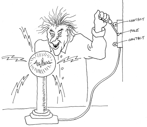
Figure 2-31. Left: Mad scientist. Right: SPDT knife switch.
To make things more interesting, you can buy switches that have three or four poles. (Some rotary switches have even more, but we won’t be using them.) Also, some double-throw toggle switches have an additional “center off” position.
Putting all this together, I made a table showing some possible types of switches and the abbreviations that describe them. Pushbuttons use the same abbreviations. See Figure 2-32. If you’re reading a parts catalog, you can check this table to remind yourself what the abbreviations mean.
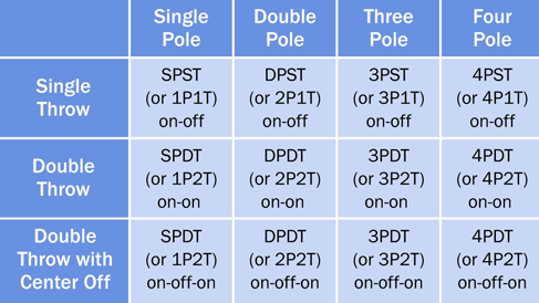
Figure 2-32. This table summarizes various options for toggle switches (and pushbuttons).
Some switches are spring-loaded, so that they snap back to a default position when you release pressure on them. When you see ON or OFF in parentheses, you know that you have to maintain pressure on the switch to keep it in that position.
Here are some examples:
-
OFF-(ON): Because the ON state is in parentheses, it’s the momentary state. Therefore, this is a single-pole switch that makes contact only when you push it, and flips back to make no contact when you let it go. It is also known as a “normally open” momentary switch, abbreviated “NO.” Most pushbuttons also work this way.
-
ON-(OFF): The opposite kind of momentary switch. It’s normally ON, but when you push it, you break the connection. So, the OFF state is momentary. It is known as a “normally closed” momentary switch, abbreviated “NC.”
-
(ON)-OFF-(ON): This switch has a center-off position. When you push it either way, it makes a momentary contact, and returns to the center when you let it go.
Other variations are possible, such as ON-OFF-(ON) or ON-(ON). As long as you remember that parentheses indicate the momentary state, you should be able to figure out how these switches behave.
Sparking
When you make and break an electrical connection, it tends to create a spark. Sparking is bad for switch contacts. It erodes them until the switch doesn’t make a reliable connection anymore. For this reason, you must use a switch that is appropriate for the voltage and amperage that you are dealing with.
The electronic circuits in this book are low-current and low-voltage, so you can use almost any switch; but if you are switching a motor, it will tend to suck an initial surge of current that is at least double the rating of the motor when it is running constantly. For instance, you should probably use a 4-amp switch to turn a 2-amp motor on and off.
Checking Continuity
You can use your meter to check a switch. Doing this enables you to find out which contacts are connected when you turn a switch one way or the other. It’s also useful if you have a pushbutton and you can’t remember whether it’s the type that is normally open (you press it to make a connection) or normally closed (you press it to break the connection).
It’s convenient to set your meter to measure “continuity” when checking a switch. The meter will beep (or show a visual indication) if it finds a connection, and will do nothing if it doesn’t. See Figure 2-33, Figure 2-34, and Figure 2-35 for examples of meters that are set to measure continuity. Remember that in Experiment 1, I showed you the symbol that is used on meters to represent continuity. See Figure 1-7.
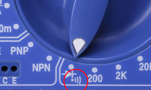
Figure 2-33. A meter dial that has been turned to measure continuity.
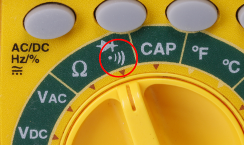
Figure 2-34. Another meter dial set to measure continuity.
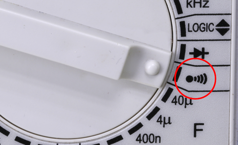
Figure 2-35. A third meter measuring continuity.
Background: Early Switching Systems
Switches seem to be such a fundamental feature of our world, and their concept is so simple that we can easily forget that they went through a gradual process of evolution. Primitive knife switches were quite adequate for pioneers of electricity who simply wanted to connect and disconnect some apparatus in a laboratory, but a more sophisticated approach was needed when telephone systems began to proliferate. Typically, an operator at a “switchboard” needed to connect any pair of 10,000 lines on the board. How could it be done?
In 1878, Charles E. Scribner (shown in Figure 2-36) developed the “jack-knife switch,” so called because the part of it that the operator held looked like the handle of a jack knife. Protruding from it was a plug, and when the plug was pushed into a socket, it made contact inside the socket. The socket, in fact, contained the switch contacts.

Figure 2-36. Charles E. Scribner invented the “jack-knife switch” to satisfy the switching needs of telephone systems in the late 1800s. Today’s audio jacks still work on the same principle.
Audio connectors on guitars and amplifiers still work on the same principle, and when we speak of them as being “jacks,” the term dates back to Scribner’s invention. Switch contacts are still mounted inside a jack socket.
Today, of course, telephone switchboards have become as rare as telephone operators. First they were replaced with relays—electrically operated switches, which I’ll talk about later in this chapter. And then the relays were superceded by transistors, which made everything happen without any moving parts. In Experiment 10, you’ll be switching current with transistors.
Introducing Schematics
In Figure 2-37, I’ve redrawn the circuit from Figure 2-26 in a simplified style known as a “schematic.” From this point onward, I will be illustrating circuits with schematics, because they make the connections easier to understand. You only need to know a few symbols to interpret them.
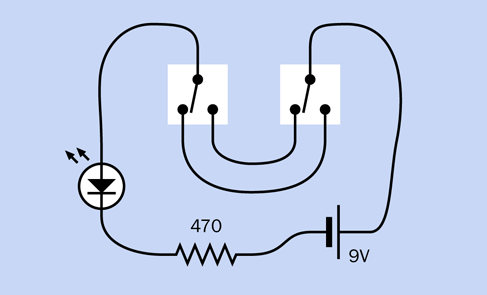
Figure 2-37. The circuit with two switches is redrawn here as a schematic.
Figure 2-26 and Figure 2-37 both show the same components and connections between them. In the schematic, the zigzag thing is the resistor, the symbol with two diagonal arrows is the LED, and the battery is shown as two parallel lines of unequal length.
The large triangle in the LED symbol indicates the direction of flow of conventional current, meaning the imaginary flow that runs from positive to negative. The pair of diagonal arrows tells you that this is the type of diode that is light-emitting (I’ll get to other kinds of diodes later). In the battery symbol, the longer of the two lines identifies the positive side.
Trace the path that electricity can take through the circuit and imagine the switches turning one way or the other. You should see clearly, now, why either switch will reverse the state of the LED from on to off or off to on.
Figure 2-38 shows the same schematic cleaned up a bit. The lines are straight, and the power supply is now shown with the positive side at top-left, and the negative side at bottom-right. You tend to see conventional current moving from top to bottom, in schematics, while signals of some kind (such as the audio input to an amplifier) move from left to right. The top-down organization of a circuit makes it easier to understand.
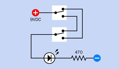
Figure 2-38. The previous schematic has been reorganized along more conventional lines.
The important thing to grasp is that the two schematics show exactly the same circuit, even though they look different. The type of components, and the way in which they are connected, are all that matters. The exact locations of the components are irrelevant.
-
A schematic doesn’t tell you where to put the components. It just tells you how to join them together.
Incidentally, you probably have an example of the circuit in Figure 2-38 in your home, especially where two light switches are placed at the top and at the bottom of a flight of stairs, and either switch can be used to turn a light on and off. This is shown in Figure 2-39, where the live and neutral wires of the AC supply enter the picture at bottom-left. The live wire is switched, while the neutral wire runs alongside it to the lightbulb (the white circle with a curly line representing the element of an old-fashioned incandescent bulb).
The only problem with schematics is that some symbols are not standardized. You may see several variants that all mean the same thing. I will be explaining them as we go along.
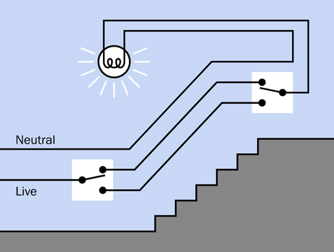
Figure 2-39. The same circuit as shown in the previous figure is used in homes where two switches control a single light.
Fundamentals: Basic Schematic Symbols
1. The Switch. Figure 2-40 shows five variations of that most basic component, a single-pole, single-throw switch. In each case, the pole happens to be on the right, while the contact is on the left—although with a SPST switch, this does not make a significant difference. In this book I have chosen to include a white rectangle around each switch, to emphasize that although it has two parts, they constitute one component.
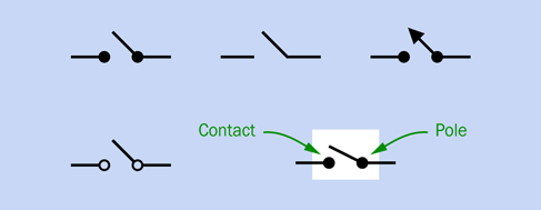
Figure 2-40. Five variations in the schematic symbol for a SPST switch. They are all functionally identical.
Figure 2-41 shows how things get a little more complicated when you have a double-throw, double-pole switch. A dashed line indicates that both segments of the switch move together when the switch is turned, even though each pole and set of contacts is electrically isolated from the other. The variation at center is sometimes found in large schematics where the layout makes it difficult to put the sections of a switch close to each other. Each set of contacts is identified by an abbreviation ending in A, B, C . . . and you are expected to understand that the contacts are actually contained in one switch.
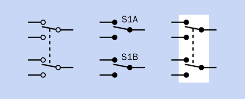
Figure 2-41. Three variations on a DPDT switch symbol.
2. Power Supply. The power supply for a DC (direct-current) circuit can be indicated in several ways. The top section of Figure 2-42 shows symbols for a battery. A short line indicates the negative end, while a longer line indicates the positive end. Traditionally, a single pair of lines represented a single 1.5-volt cell, two pairs indicated a 3-volt cell, and so on. But when circuits used high voltage with vacuum tubes, the person drawing the schematic would usually show a dashed line between cells instead of drawing dozens of them in a row.
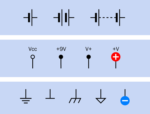
Figure 2-42. Various ways to show positive and negative DC power in a circuit.
A battery symbol may still be used in a simple schematic, but more often positive and negative DC power is indicated by separate symbols, shown in the center section and the bottom section of Figure 2-42. Positive is applied in one location of a circuit labelled Vcc, VCC, or V+, or +V, or +V with a number added to indicate the voltage. Originally the term VC referred to the voltage at the collector of a transistor. VCC meant the supply voltage for the whole circuit, and is now used regardless of whether the circuit has any transistors in it. Many people say “vee cee cee” without knowing its derivation.
In this book, because I have the luxury of full-color reproduction, I have used a plus symbol in a red circle to indicate positive power input.
The negative side of the power supply can be shown with any of the symbols in the bottom section of Figure 2-42. It may be referred to as “negative ground” or simply “ground.” Because many parts of a circuit may share a negative potential, multiple ground symbols may be found scattered around a schematic. This is more convenient than drawing lines linking them all together.
In this book, I have chosen to use the minus sign in a blue circle because it is so intuitively obvious. You will not see it used often in schematics generally.
My discussion so far has referred to battery-powered devices. In a gadget that uses AC power from a wall outlet, the situation is more complicated, because the outlet has three sockets in it for live, neutral, and ground connections. A schematic typically shows the AC source as an S shape turned on its side, as in Figure 2-43. Often the value of the power supply is shown, and in the US it is usually 110, 115, or 120 volts. Elsewhere in the circuit, the symbols shown on the righthand side of Figure 2-43 refer to the chassis of the device in which the electronics are mounted.

Figure 2-43. Symbolic representation of AC power (left) and chassis in an AC device (right).
Note that the ground pin in an AC power outlet in the home really does connect with the ground outside the building. An electronic device with a metal chassis that connects with that pin is “grounded.” In a battery-powered circuit without any high voltages, grounding “in the ground” is unnecessary, but a ground symbol may still be used.
In the UK, a grounded device is sometimes referred to as being “earthed.”
3. Resistor. Only two variants of the symbol for a resistor exist, shown in Figure 2-44. The symbol on the left is used in the United States, with a number beside it indicating its resistance in ohms. Alternatively the resistor may be identified as R1, R2, R3 . . . with a separate parts list showing the values. The righthand symbol in Figure 2-44 originated in Europe, and here again the number is the value of the resistor in ohms. The value of 220 ohms in the figure was selected arbitrarily.

Figure 2-44. Symbol for a resistor in the United States (left) and Europe (right).
Remember that where a resistance value includes a decimal point, Europeans omit the point and substitute a K or M, while resistances less than 1K are shown as one or more digits followed by letter R.
4. Potentiometer. In Figure 2-45 the lefthand symbol is used in the United States, while the righthand symbol originated in Europe. In both symbols, the arrow identifies the wiper in the potentiometer. The value of 470 ohms was selected arbitrarily.

Figure 2-45. The lefthand symbol for a potentiometer is used in the United States, while the righthand symbol originated in Europe.
5. Pushbutton. Three possible pushbutton symbols are shown in Figure 2-46. These symbols represent the most common type of normally open pushbutton or momentary switch, where pressure closes two contacts and release of the pressure opens the circuit. In more complex pushbuttons, where a single button press closes or opens numerous contacts, the symbol for a multi-pole switch may be used.

Figure 2-46. Three variants of the pushbutton symbol. The white rectangle is added in this book for clarity, but is not used elsewhere.
6. Light-Emitting Diode (LED). Figure 2-47 shows four variants of a symbol representing an LED. The meaning is the same, regardless of whether a circle is included, and regardless of whether the triangle is solid or open. The white highlight in the circle is added in this book for clarity, but is not used elsewhere. LED symbols may be oriented in any direction, for convenience in drawing a circuit. Arrows also may point in any direction.

Figure 2-47. Four ways of representing an LED. They are functionally identical.
I’ll explore other symbol variants later in the book. Meanwhile, the most important things to remember are:
-
The positions of components in a schematic do not affect the functionality.
-
The styles of symbols used in a schematic are not important.
-
The connections between the components are extremely important.
Schematic Layout
I mentioned previously that schematics commonly show positive power at the top and negative at the bottom. This convention is a great help in understanding how the circuit works, but is not helpful at all when you actually want to build the circuit, because almost certainly you will begin by using a breadboard that imposes a completely different geometry.
Almost all the electronics books that I have seen expect you to change a circuit from the way it looks as a schematic to the way it has to be on a breadboard. This can be challenging, and may be a significant barrier to learning electronics. Therefore, the schematics in this book are all laid out in a pattern that is similar to that of a breadboard. This will make more sense after you encounter a breadboard yourself in Experiment 8.
Crossovers
The last topic I have to mention about schematics concerns the way in which they show two wires crossing each other. In the simple circuits that you have built so far, no crossovers occurred, but as circuits become more complicated, wires must pass over each other without making an electrical connection. How can a schematic illustrate this?
In the first edition of this book, I used a style in which one wire crossing another had a little semicircular “jump” in it. This is identified as the “Old Style” in Figure 2-48. I still prefer this style, because you can see so clearly that the wires are not making an electrical connection. However, a few decades ago, rendering the little jump became more troublesome as circuits were created with graphics software instead of pen and ink. At that point, jumps were used less frequently.
An alternative, identified as “Newer Style” in Figure 2-48, showed one of the wires with a break in it. This was confusing, and was not easily rendered by automated circuit-drawing software. Consequently it, too, has become rare.
The third style, labelled “Conventional,” is now extremely common. In this edition of Make: Electronics I decided I should conform with the conventional style that is used in the rest of the world, even though I think it isn’t as clear as the old style.
Perhaps you are wondering—if two lines crossing each other are not electrically connected, how do you draw them when they are connected? The answer is, you use a dot, and to avoid confusion, the dot should be large, not just a little pin-prick. The lower half of Figure 2-48 shows what I mean. This leads to the general rule:
-
Two lines crossing each other do not indicate an electrical connection.
-
Where lines intersect in a dot, there is an electrical connection.
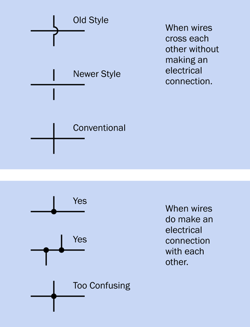
Figure 2-48. Various styles for depicting wires that do or do not connect. See text for details.
There’s still one more note to add. In the interests of clarity, I think it’s good practice to avoid the style shown at the bottom of Figure 2-48. It’s too confusing. If we avoid that configuration, and use the one immediately above it instead, then we know that wires crossing each other never make a connection under any circumstances.
Colored Conductors
Did I say that crossovers would be my last topic about schematics? Actually there is one more small matter. Because I never want you to get confused between the positive and negative sides of a power supply, I’m going to be coloring all the positive conductors red in schematic drawings in the rest of the book, while the negative/ground side will be blue. Readers have told me that this was very helpful where I used it occasionally in the past, so, now I’m going to use it consistently throughout.
Black is a more commonly used color for negative/ground (as in the black wire on your meter, or the black wire from a battery connector). But blue is still sometimes used, and is more distinctive.
Just bear in mind that schematics that you encounter in the world outside of this book will not use this helpful coloring convention. All the wires will be black, and you will have to figure out which ones are connected with the power supply.
Experiment 7: Investigating a Relay
The next step in your exploration of switching is to use a remote-controlled switch. By “remote-controlled,” I mean that it turns on or off in response to a signal that you send to it. This kind of switch is known as a relay, because it relays an instruction from one part of a circuit to another.
-
Often a relay is controlled by a low voltage or small current, and switches a larger voltage or higher current.
This can be very useful. When you start your car, for instance, a relatively small, cheap ignition switch sends a small signal down a thin, inexpensive piece of wire to a relay that is near the starter motor. The relay activates the motor through a shorter, much thicker, more expensive piece of wire, capable of carrying as much as 100 amps.
Similarly, if you raise the lid on an old-fashioned top-loading washing machine during its spin cycle, you close a small switch that sends a small signal down a thin wire to a relay. The relay handles the bigger task of switching off the large motor spinning the drum full of wet clothes.
What You Will Need:
-
9-volt battery (1)
-
DPDT 9VDC relays (2)
-
Tactile switch, SPST (1)
-
Test leads with alligator clips at each end (5)
-
Utility knife (1)
-
Multimeter (1)
The Relay
The type of relay that I want you to use has two pins at one end and six at the other. The six are clustered in two lines of three, as in Figure 2-49 (where the relay is upside-down with its pins in the air). If you buy two relays, you can use one for investigational purposes, meaning that you’ll be cutting it open to take a look inside. If you do this very, very carefully, the relay should still be usable afterward. If not—well, you will have a spare.
Caution: Polarity Problems
Some relays are fussy about the way that you apply voltage to the coil that’s hidden inside. Everything works fine with the electricity flowing one way through the coil, but if you reverse the positive and negative connections (in other words, if you reverse the polarity) the relay stops working.
This is especially annoying when the relay datasheet doesn’t make it clear. The relays that I have recommended do not require a particular polarity. See “Essential: Relay”.
Procedure
Attach test leads and a tactile switch (pushbutton) as shown in Figure 2-49. (Note that the parts in these drawings are not drawn to scale.) When you press the button to apply 9 volts to the pair of pins that are separate from the others, you should hear a very faint click. Let go of the button, and you may hear another click. (If your hearing is not good, touch the relay gently with your fingertip, and you should feel a faint vibration when the click occurs.)
What’s happening here? Your meter will help you to investigate. Set it to measure continuity, and verify that it’s working by touching the two probes together. If it doesn’t beep, you haven’t set it to measure continuity, or the battery is dead, or one of the probes is plugged into the wrong socket.
Now hold the probes against the pins as shown in Figure 2-50, and press the button. The meter should beep while the button is pressed.
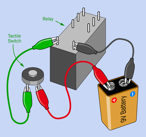
Figure 2-49. The first step in figuring out what’s happening inside a relay.
This test tells you that some contacts must close inside the relay when you apply voltage to the pair of terminals at the end nearest you. But maybe you’re having difficulty holding the meter probes against the pins at the same time as you press the button. In that case, try using a couple of test leads as shown in Figure 2-51. With one end of each lead clipped to a meter probe, and the other end of each lead clipped to a relay pin, you have your hands free.
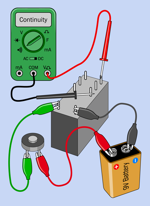
Figure 2-50. Step 2: Measuring continuity.
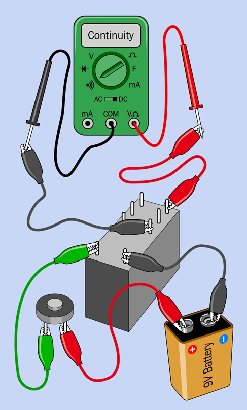
Figure 2-51. You can extend your meter probes with test leads, to free yourself from holding the probes.
Now try moving the red test lead from the relay pin farthest away from you to the vacant pin next to it. You should find that the behavior of the meter is reversed, so that it beeps when you don’t press the button, and then stops beeping when you do press it.
What’s Going On Inside
Figure 2-52 shows an x-ray view of the interior of the relay when you pressed the button. The relay contains a coil at the bottom, which generates a magnetic field, which moves a pair of internal switches. The coil moved the switch on the right to connect pins A and C internally, so the meter beeped.
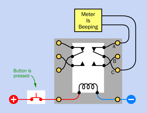
Figure 2-52. Inside the relay, when the button is pressed, the meter starts beeping.
You may be wondering why the coil in the relay seems to push the internal switch away from it. The reason is that there is a mechanical linkage inside the relay which converts a pulling force to a pushing force. You’ll be able to inspect this when I get to the point of opening up the relay, later in this experiment.
Figure 2-53 shows what happened when you were not pressing the button. The switch contacts relaxed into their opposite state, breaking the connection between A and B and making the connection between B and C. The contacts remain in this position when no power is flowing through the relay coil.
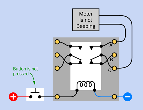
Figure 2-53. Inside the relay, when the button is not pressed and the meter is not beeping.
Other Relays
I believe that the pin functions that I have described are the most common for this size of relay, but I know there are some exceptions that do things differently. In fact, the first edition of this book used a relay that had different pin functions.
When you encounter a double-pole, double-throw (DPDT) relay for the first time, how can you determine what’s going on inside it? You test different pairs of pins with your meter while you apply voltage to the coil. By a process of elimination, you can figure out how the pins are connected.
You can also read the manufacturer’s datasheet. It should contain diagrams such as the one in Figure 2-21.
Is this all you need to know about relays? No, I’ve hardly scratched the surface.
-
Some relays are latching, meaning that the internal switches remain in either position when the power is off. Latching relays usually have two coils to move the switches each way. I will not be using them in this book.
-
Some relays have two poles, some have only one; some are double-throw, and some are single-throw.
-
Some coils switch with AC, some switch with DC, and as I’ve mentioned previously, some DC coils require you to apply DC voltage with correct polarity.
As always, datasheets should provide the necessary information.
Figure 2-54 shows a selection of schematic symbols for various types of relays. Type A is single-pole, single-throw. Type B is single-pole, double-throw. Type C is single-pole, single-throw, drawn in the style that I like to use, with a white rectangle reminding you that the parts are enclosed in a single component. Type D is single-pole, double-throw. Type E is double-pole, double throw. Type F is single-pole, double-throw, latching.
Relay schematics are always drawn with the internal switch in its relaxed position, when power is not applied—with the exception of the latching relay, where the position of the switch is arbitrary.
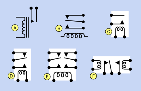
Figure 2-54. Various schematic symbols for relays. See text for details.
The type of relay you have been testing is a small-signal relay, meaning that it can’t switch a lot of current. Larger relays may be capable of switching many amperes. It’s important to choose a relay that is rated for the maximum current in your circuit (or higher), because overloading a relay will cause sparking that quickly erodes its contacts.
In future experiments you’ll discover some practical uses for a relay—for example, in a home security system. Before you get to that, I’m going to show you how to turn a relay into an oscillator that buzzes. But first, I think it’s time to take a look inside.
Opening It Up
If you have an impatient disposition, you can open your relay using methods such as those in Figure 2-55 and Figure 2-56. Generally, though, you may be better off using a most mundane piece of equipment: a box cutter or utility knife.

Figure 2-55. Option 1 for opening a relay (probably not recommended).

Figure 2-56. Option 2 for opening a relay (definitely not recommended).
Figure 2-57 and Figure 2-58 illustrate the technique that I like to use. You shave the edges of the plastic shell, beveling them until you see just a hair-thin opening. Don’t go any farther; the parts inside are very, very close to your knife blade. Now pop the top off. Repeat this procedure with the remaining edges of the shell, and if you were really careful, the relay will be exposed but will still work when you energize its coil.
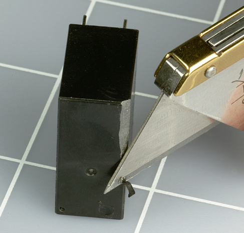
Figure 2-57. Shaving the edges of the plastic box of a relay is a first step to opening it. Always cut away from you and downward toward your work bench.
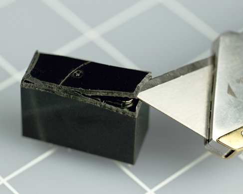
Figure 2-58. After shaving the edges, you should be able to pry open one section of the case.
What’s Inside?
Figure 2-59 shows a simplified view of the parts in a typical relay. The coil, A, generates a magnetic attraction pulling lever B downward. A plastic extension, C, pushes outward against flexible metal strips and moves the poles of the relay, D, between the contacts. (This is a slightly different configuration from the relay recommended for experiments in this book, but the general principle is the same.)
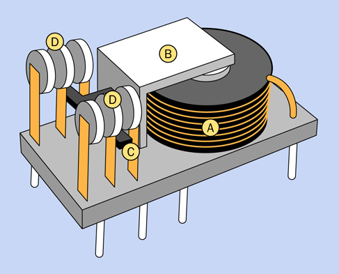
Figure 2-59. Simplified view of the interior of a relay. See text for details.
You can compare the diagram with an actual relay that I opened up, in Figure 2-60.
Various sizes of relays are shown with their cases removed in Figure 2-61. All of them happen to be designed for 12 volts DC. The automotive relay at far left is the simplest and easiest to understand, because it is designed without much concern for the size of the package. Smaller relays are more ingeniously designed, more complex, and more difficult to figure out. Usually, but not always, a smaller relay is designed to switch less current than a larger one.
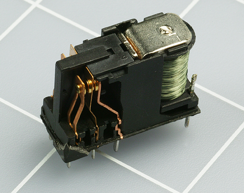
Figure 2-60. An actual relay, exposed. The squares on the cutting mat are 1” x 1”.
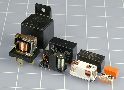
Figure 2-61. A variety of 12-volt relays. See text for details.
Fundamentals: Relay Terminology
Coil voltage is the voltage that the relay is supposed to receive when you energize it. This may be AC or DC.
Set voltage is the minimum that the relay will accept, to close its switch. This will be a bit less than the ideal coil voltage. In practice, a relay will probably work with even less power than the set voltage, but the set voltage tells you the minimum at which it is guaranteed to work.
Operating current is the power consumption of the coil, usually in milliamps, when the relay is energized. Sometimes the power is expressed in milliwatts.
Switching capacity is the maximum amount of current that the contacts inside the relay can switch without damage. Usually this is specified for a resistive load, meaning a passive device such as an incandescent lightbulb. When you use a relay to switch on a motor, it imposes an inductive load, which takes a big initial surge of current before it gets up to speed. Switching the motor off creates another surge. If the datasheet for a relay doesn’t rate its ability to handle an inductive load, a rule of thumb is to assume that a motor may draw twice as much current when it starts, compared with when it is running.
Experiment 8: A Relay Oscillator
When you used test leads with alligator clips in previous experiments, they had two big advantages: you could assemble a circuit quickly, and you could see its connections easily.
Sooner or later, though, you have to get acquainted with a quicker, more convenient, more compact, and more versatile method for building circuits, and that time has come. I’m referring to the most widely used prototyping device: a solderless breadboard.
In the 1940s, circuits were built on a platform that really did look like a board that could be used for slicing bread. Wires and components were nailed, stapled, or screwed into place, because this was a whole lot easier than the alternative, which was mounting them on pieces of sheet metal. Remember, plastic barely existed back then. (A world without plastic—can you imagine it?)
Today the term “breadboard” is used for a little slab measuring about 2” by 7”, and no more than 1/2” thick, as pictured in Figure 2-10. This is a wonderfully quick and easy system for assembling components. The only problem is that it creates internal connections between the components that are difficult to visualize—although I have ways to help you deal with that.
The best way to learn breadboarding is to assemble a circuit, which is exactly what you are about to do, taking the previous experiment with a relay one step further.
What You Will Need
-
9-volt battery (1)
-
Battery connector (1)
-
Breadboard (1)
-
DPDT 9VDC relay (1)
-
Generic LEDs (2)
-
Tactile switch (1)
-
Resistor, 470 ohms (1)
-
Capacitor, 1,000µF (1)
-
Pliers, wire cutters, wire strippers (1 each)
-
Hookup wire, at least two colors, no more than 12” each
A Beginner’s Board
Figure 2-62 shows the top part of your breadboard with the components that I would like you to plug into it.
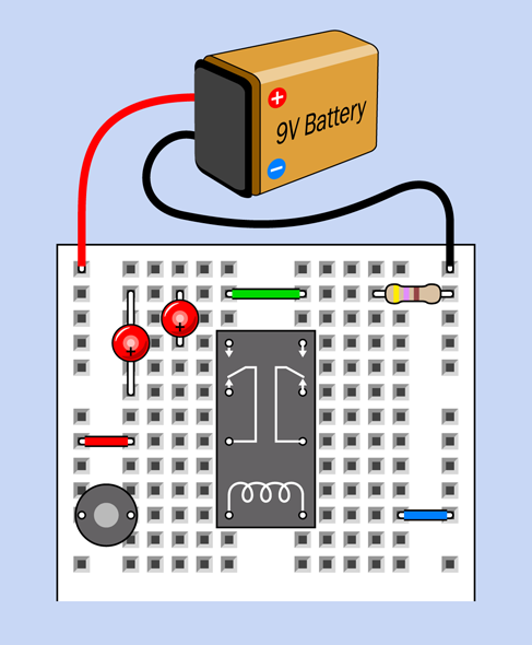
Figure 2-62. A relay test circuit mounted in a breadboard.
In case you’re wondering exactly what some of these components are, Figure 2-63 shows all the pictorial symbols that will be used in the rest of the book in breadboard diagrams. You have not encountered most of these components yet, but you can refer back to this diagram for reference.
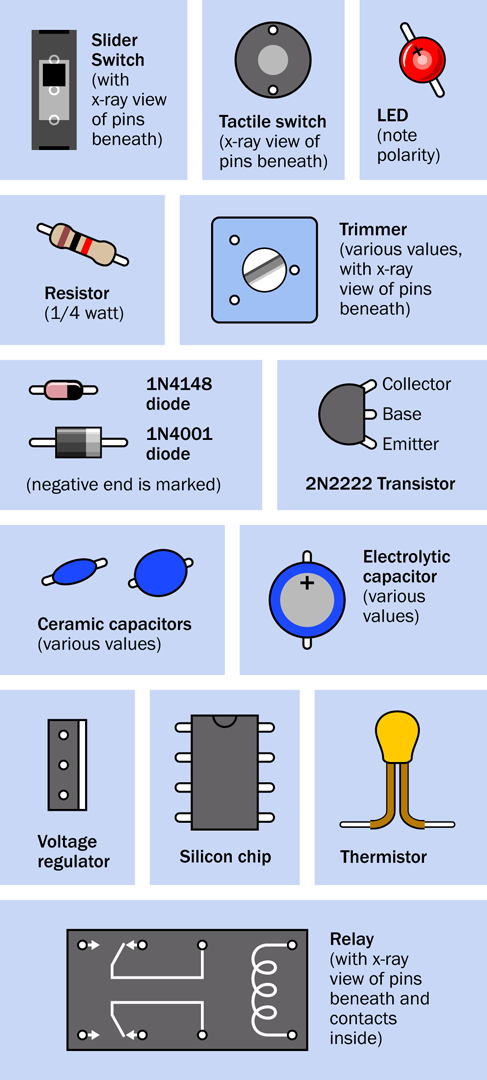
Figure 2-63. Representation of breadboarded components.
In Figure 2-62 the relay from the previous experiment is in the center. You won’t be able to see the pins from above, because they are inserted into the board underneath. I have shown their positions so that you know which way around the relay should be (that is, with its coil pins at the bottom). I have also shown the connections that exist inside the relay, just to remind you how they are configured. The switch is in the position where it rests when there is no power. This is the “relaxed” position.
The gray circular object is your pushbutton, more properly known as a tactile switch. I have shown an x-ray view of its pin positions, too, so you know how it should be oriented.
The two red circular objects are LEDs. Make sure the long lead of each one is on the side where the plus sign is shown.
The resistor value is 470 ohms—but you could have figured that out by looking at the colors of its stripes.
The red, green, and blue segments that look like pieces of wire, plugged into the breadboard, really are pieces of wire, plugged into the breadboard. My next task is to tell you how to make them.
Making Jumpers
If you bought an assortment of precut hookup wires, also known as jumpers, you can just go ahead and push them into the breadboard in the positions shown, although they won’t be the same colors as the ones in my illustration.
As I mentioned previously, I advocate making your own. The exact procedure that I use is shown in Figure 2-64. First, strip off a couple of inches of insulation from some hookup wire. To do this, hold the wire in your left hand (or your right hand, if you are lefthanded). Hold the wire strippers in your other hand. Close the wire strippers so that they grip the wire in the hole marked “22” on the blade of the strippers. Pull the strippers away from your other hand, and they should take the insulation with them. (If you are wondering why you use the hole marked “22,” it’s because you are using 22-gauge wire. At least, I hope that’s the size you are using.)
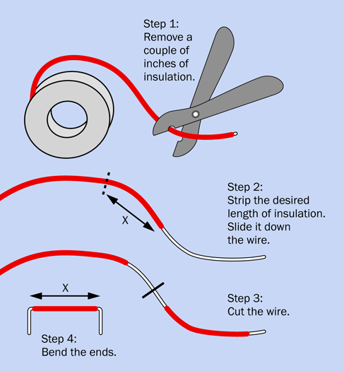
Figure 2-64. Procedure for making jumper wires. See text for details.
Next assess how long the visible part of your wire is supposed to be when it is installed on the board. I will call that distance X inches. Measure X inches of the insulation that remains on your hookup wire. Drag a section of insulation that is X” long until it is about 3/8” from the end of the wire.
Using your wire cutters, or the blades built into your wire strippers, snip the wire 3/8” behind the X” section of insulation that you just dragged along the wire.
Finally, use your pliers to make a neat right-angle bend at each end, and push it into the board. Wait—does it not quite fit? If you practice a little, you’ll soon get to the point where you can make jumpers of the right length just by visual estimation.
Power Up
Lastly you need to apply power from your 9-volt battery. You should find that the wires attached to the connector terminate in little bare soldered ends that will poke into the holes in the breadboard. If you have trouble with them, try feeding them in with the tips of your pliers. If you still have trouble, you may need to strip off a couple more millimeters of insulation, using your wire strippers.
After inserting the wires into the breadboard, snap the connector onto the battery, as suggested in Figure 2-62. As soon as you have power on the breadboard, the LED on the left should light up. When you press the button, the switch inside the relay will close and the LED on the right will light up. Congratulations! You just breadboarded your first circuit.
Now, why does it work?
Inside the Board
Figure 2-65 reveals the copper strips that are hidden inside the breadboard. The little squares show where each lead of a component can poke through and make contact with the strips inside.
Each of the two long, vertical strips is known as a bus (plural: buses). This type of bus does not transport people, but does transport electrons, as the positive and negative sides of the power supply are typically connected with the buses.
-
In this book, I am consistently placing the positive side of the supply on the left bus and negative ground on the right bus.
An important thing to notice is that each bus has two breaks in it. Not all breadboards have this feature, but many do. The purpose is to allow you to use multiple power supplies of different voltages at different locations on the board. In practice this doesn’t happen often, and the breaks in the buses are annoying, because you may tend to forget that they’re there. When you build a circuit that extends down the board, and you find a mysterious lack of power around the halfway mark, you may realize eventually that you forgot to add jumper wires bridging the gaps in the buses.
Where necessary, I will be reminding you to take care of this little detail.
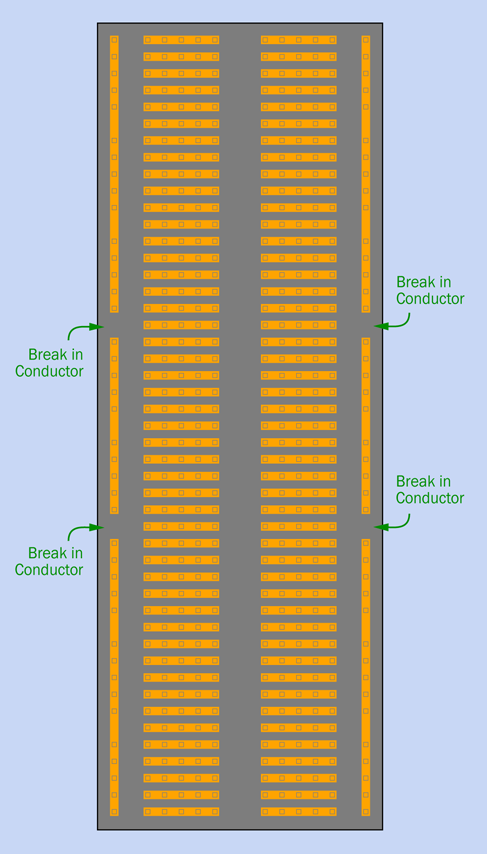
Figure 2-65. A single-bus breadboard contains copper connecting strips in this configuration.
Relay Circuit, Revealed
Figure 2-66 shows you the copper strips hidden inside your breadboard. They make connections between components plugged into the breadboard. The electricity takes a zigzag path, but the resistance of the copper strips is so low, the length of the path doesn’t matter.
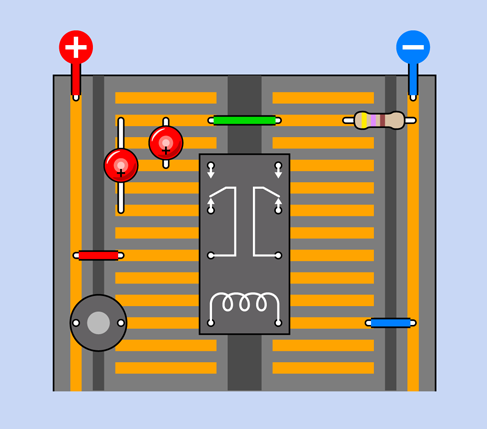
Figure 2-66. Components on the breadboard are connected through the copper strips inside it.
Maybe the diagram is easier to understand if I hide the copper strips that aren’t doing anything, and just show the ones that are part of the circuit, as shown in Figure 2-67.
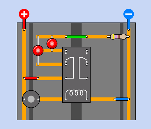
Figure 2-67. The previous diagram is modified so that strips in the breadboard that are not an active part of the circuit have been omitted.
Now take a look at the schematic for the same circuit, in Figure 2-68. I laid out the schematic to resemble the breadboard, to emphasize the similarity. As you continue through the book I’m going to rely on schematics more, and will expect that you can create your own breadboard layouts. But I’ll take a while to get to that point.
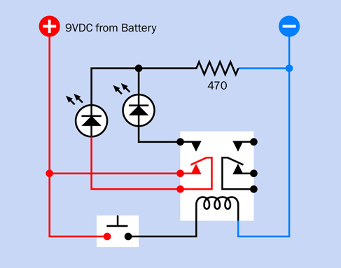
Figure 2-68. A schematic that corresponds with the breadboard connections already shown.
If you’re wondering why there is only one 470-ohm resistor to protect two LEDs, it’s because the LEDs only light up one at a time.
Making It Buzz
The next step is to modify your circuit, to make it more interesting. Look at the new schematic in Figure 2-69. Compare it with the previous version in Figure 2-68. Can you spot the difference? In the old version, the pushbutton that energized the coil received its power directly from the 9V supply. In the new version, the pushbutton gets its power through the lower contact of the relay. What effect will this have?
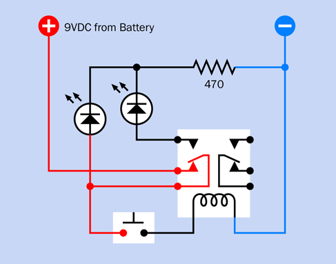
Figure 2-69. A revised version of the previous schematic now delivers power to the pushbutton through the lower contact of the relay.
Figure 2-70 shows how you can adapt your previous breadboarded circuit to match the new schematic. All you have to do is rotate the pushbutton by 90 degrees, and use an extra jumper wire (colored green in the figure) to link it with the same relay pin that energizes the lefthand LED.
Push the button—briefly!—and what happens? The relay makes a buzzing sound. (If your hearing is not good, touch the relay to feel it vibrating.)
Can you see what’s happening, here? In its relaxed state, the switch inside the relay rests against the lower contact. This feeds positive voltage to the lefthand LED, and also to the pushbutton. Consequently, when you press the button, the power connects with the relay coil. The coil pushes the internal switch upward—but as soon as it does that, it breaks the connection feeding voltage to the coil. So, the switch falls back to its relaxed position. But this energizes the coil again, so the cycle repeats.
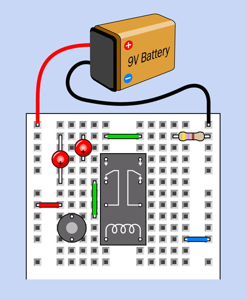
Figure 2-70. The previous breadboarded circuit has been modified to match the revised schematic.
The relay is oscillating between its two states.
Because you’re using a small relay, it switches on and off quite fast. In fact, it oscillates perhaps 20 times per second (too fast for the LEDs to show what’s really happening).
-
When you force a relay to behave like this, it’s liable to burn itself out or destroy its contacts. You are also controlling a bit more current than your tactile switch is designed to handle. So don’t hold down the button for long! To make the circuit less self-destructive, we need to make everything happen more slowly. I’m going to achieve this by using a capacitor.
Adding Capacitance
Add a 1,000µF electrolytic capacitor in parallel with the coil of the relay as shown in the diagram in Figure 2-71, making sure that the capacitor’s short wire is connected to the negative side of the circuit; otherwise, it won’t work. In addition to the short wire, you should find a minus sign on the body of the capacitor, which is there to remind you which side should be more negative. In the diagram, I used a plus symbol, because it’s more obvious than a minus symbol, and I wanted to be consistent with the style I used for LEDs.
-
Electrolytic capacitors react very badly to being connected the wrong way around. They may self-destruct. Double-check the polarity.
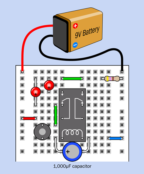
Figure 2-71. With the addition of a large capacitor, the behavior of the circuit slows down.
When you press the button now, the relay should click intermittently instead of buzzing.
A capacitor is like a tiny rechargeable battery. It’s so small that it charges in a fraction of a second, before the relay has time to open its lower pair of contacts. Then, when the contacts are open, the capacitor releases its power to the relay (and to the lefthand LED). This keeps the coil of the relay energized for a moment. After the capacitor exhausts its power reserve, the relay relaxes and the process repeats.
During this process, the capacitor is charging and discharging.
Disconnect the righthand LED, and you should find that the lefthand LED pulses in a pleasing manner, gradually fading as the voltage from the capacitor diminishes.
Because the capacitor takes a big surge of current when it charges, your tactile switch may overheat if you hold it down for too long during this experiment.
Fundamentals: Farad Basics
The storage ability of a capacitor is measured in farads, represented by an uppercase letter F. The term is named after Michael Faraday, another in the pantheon of electrical pioneers.
The farad is a large unit, and is divided into microfarads (abbreviated µF, each being 1/1,000,000th of a farad), nanofarads (abbreviated nF, each being 1/1,000th of a microfarad), and picofarads (abbreviated pF, each being 1/1,000th of a nanofarad). In the United States, the nanofarad is used less often than in Europe. Instead, values may be expressed using picofarads and fractions of a microfarad.
A conversion table for picofarads, nanofarads, microfarads, and farads is shown in Figure 2-72.

Figure 2-72. Conversion table for fractions of farads.
Caution: Getting Zapped by Capacitors
If a large capacitor is charged with a high voltage, it can retain that voltage for minutes or even hours. Because the circuits in this book use low voltages, you don’t have to be concerned about this here, but if you are reckless enough to open an old TV set and start digging around inside (which I do not recommend), you may have a nasty surprise. A large charged capacitor can kill you as easily as if you stick your finger into an electrical outlet.
Fundamentals: Capacitor Basics
No electrical connection exists inside a capacitor. Its two leads are connected internally with plates that are a tiny distance apart, separated by an insulator known as the dielectric. Consequently, DC current cannot flow through a capacitor. However, if you connect a capacitor across a battery, it will charge itself as suggested in Figure 2-73, because the charge on one plate attracts an opposite charge on the other plate.

Figure 2-73. A capacitor connected across a battery will accumulate equal and opposite charges, as suggested here.
In modern capacitors, the plates have been reduced to strips of very thin, flexible, metallic film.
The two most common varieties of capacitors are ceramic (usually small, to store a relatively small charge) and electrolytic (which can be much larger). Electrolytics are usually shaped like miniature tin cans and may be any color, although black is most common. Older ceramics are often disc-shaped, while newer ones are little rounded blobs.
Ceramic capacitors have no polarity, meaning that you don’t have to worry about which way around they are in a circuit. Electrolytics do have polarity, and won’t work unless you connect them the right way around.
The schematic symbol for a capacitor contains two lines representing the two plates inside it. If both of the lines are straight, the capacitor does not have a polarity—it can be used either way around. If one of the lines is curved, that side of the capacitor must be more negative than the other. A + sign may be included to remind you of the polarity. The variants are shown in Figure 2-74.

Figure 2-74. Two variants of the symbol representing a capacitor. See text for details.
The symbol with the curved plate is not used so much anymore. People assume that if you have an electrolytic capacitor, you’ll be smart enough to connect it the right way around. Also, multilayer ceramic capacitors have become available in higher values, and may be substituted for electrolytics.
-
My schematic diagrams will only use the nonpolarized capacitor symbol. Whether you use an electrolytic capacitor or a ceramic capacitor is your choice.
-
My breadboard diagrams will show electrolytic capacitors where I think you are most likely to use them. Still, you can substitute ceramic capacitors if you wish.
Caution: Observe Capacitor Polarity!
The most common type of electrolytic capacitor uses aluminum plates. Two other types use tantalum and niobium, respectively. All of these capacitors are fussy about polarity. In Figure 2-75, a tantalum capacitor was plugged into this breadboard, connected the wrong way to a power source capable of delivering a lot of current. After a minute or so of this abuse, the capacitor rebelled by popping open and scattering small flaming pieces, which burned their way into the breadboard. Lesson learned: observe polarity!
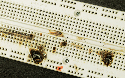
Figure 2-75. The aftermath of an error in which a polarized tantalum capacitor was connected the wrong way around to a power source capable of supplying substantial current.
Fundamentals: Fault Tracing
As you build more circuits on breadboards, and they become more complex, errors become more likely. No one is exempt from this unfortunate fact.
One frequent breadboarding error is to plug a wire into the wrong row on a breadboard. This is especially easy when you have a component such as a relay, where the pins are hidden. Often I pull that component out, take another look, and push it back in, just to make sure.
A more subtle error occurs when you forget the connections made by the strips hidden inside the board. Take a look at Figure 2-76. What could be simpler? Clearly, the positive source of power feeds current through the LED, through a jumper, and then through a resistor to the negative bus. But if you assemble the components as I have shown them, I absolutely, positively guarantee that they won’t work.
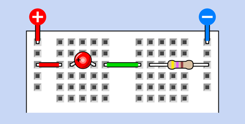
Figure 2-76. This breadboarded circuit won’t work. Can you see why?
The situation will get much worse if you swap the positions of the resistor and the LED. Now the circuit will immediately burn out the LED.
The explanation becomes apparent when you check the x-ray view in Figure 2-77. The problem is that both leads of the LED are plugged into the same strip inside the board. The electricity has the option to run through the LED, or run through the copper strip instead—and since the resistance of the strip is a tiny fraction of the resistance of the LED, most of the electrons prefer the strip, and the LED remains dark.
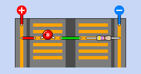
Figure 2-77. An x-ray view helps to explain why this won’t work.
Many other kinds of errors are possible. How can you find them most quickly and efficiently? You simply have to be methodical. Try to follow these steps:
-
Check voltages. Attach the red lead from your meter to a connection near the top of the positive bus on your breadboard. Set the meter to measure volts (DC volts, unless an experiment suggests otherwise). Make sure the power to your circuit is switched on. Now touch the black probe from your meter to various locations down the negative bus. The meter reading should be close to the supply voltage. If you find a value close to zero, you probably forgot to include a jumper to bridge one of the gaps in the negative bus. If you find a value of a few volts, but it is significantly lower than the supply voltage, you may have a short circuit somewhere, pulling down the voltage from the battery (if you are using a battery).
Now secure the black probe to a connection near the top of the negative bus, and check the positive bus from top to bottom.
Finally, with the black probe still attached near the top of the negative bus, use the red probe to check voltages at random locations in your circuit. If you find a voltage close to zero, probably a connection is missing somewhere, or a component or wire is not making contact inside the breadboard.
-
Check placement. Make sure that all the jumper wires and component leads are exactly where they should be on the breadboard.
-
Check component orientation. Diodes, transistors, and capacitors that have polarity must be the right way around. When you start to use integrated circuit chips, later in this book, check that they are the right way up, and make sure that none of the pins on a chip has been bent so that it is hidden underneath the chip.
-
Check connections. Sometimes (seldom, but it can happen) a component may make a bad connection inside the breadboard. If you have an inexplicable intermittent fault or zero voltage, try relocating some of the components. In my experience this problem is more likely to occur if you buy very cheap breadboards. It is also more likely if you use wire that has a smaller diameter than 22 gauge. (Remember, a higher gauge number means a thinner wire.)
-
Check component values. Verify that all the resistor and capacitor values are correct. My standard procedure is to check each resistor with a meter before I plug it in. This is time-consuming but can actually save time in the long run.
-
Check for damage. Integrated circuits and transistors can be damaged by incorrect voltages, wrong polarity, or static electricity. Keep spares on hand so that you can make substitutions.
-
Check yourself! When all else fails, take a break. Working obsessively for long periods can create tunnel vision, which prevents you from seeing what’s wrong. If you move your attention to something else for a while, then come back to your problem, the answer may suddenly appear obvious.
You may want to bookmark this list of fault-tracing procedures and come back to it later if something doesn’t work.
Background: Michael Faraday and Capacitors
As previously noted, the farad is named after Michael Faraday. He was an English chemist and physicist who lived from 1791 to 1867. See Figure 2-78.

Figure 2-78. Michael Faraday, after whom the farad is named.
Although Faraday was relatively uneducated and had little knowledge of mathematics, he had an opportunity to read a wide variety of books while working for seven years as a bookbinder’s apprentice, and thus was able to educate himself. Also, he lived at a time when relatively simple experiments could reveal fundamental properties of electricity. He made major discoveries including electromagnetic induction, which led to the development of electric motors. He also discovered that magnetism could affect rays of light.
His work earned him numerous honors, and his picture was printed on English bank notes denominated in 20 pounds sterling, from 1991 through 2001.
Experiment 9: Time and Capacitors
Electrons travel almost at the speed of light, yet we can use them to measure time in seconds, minutes, or even hours. This experiment will show you how.
What You Will Need
-
Breadboard, hookup wire, wire cutters, wire strippers, test leads, multimeter
-
9-volt battery and connector (1)
-
Tactile switches (2)
-
Generic LED (1)
-
Resistors: 470 ohms, 1K, 10K (one of each)
-
Capacitors: 0.1µF, 1µF, 10µF, 100µF, 1,000µF (one of each)
Charging a Capacitor
First set your meter to measure volts DC, and measure the voltage of a 9-volt battery with your meter. If it’s less than 9.2V, you need a newer battery for this particular experiment.
Install two tactile switches, a 1K resistor, and a 1,000µF capacitor on your breadboard as shown in Figure 2-79. Use a couple of test leads to connect your meter so that you can measure the voltage across the leads of the capacitor while keeping your hands free.
Snap a connector on your battery, and plug the wires into the breadboard to provide the 9VDC supply on the two buses of the breadboard, with positive on the left, as shown in the figure.
If the meter measures more than 0.1V, discharge the capacitor by pressing button B, which shorts together the two sides of the capacitor.
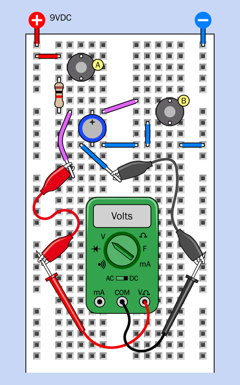
Figure 2-79. A simple setup for timing the charging of a capacitor. The capacitor is 1,000µF and the resistor is 1K.
A schematic in Figure 2-80 shows the same circuit, and may help you to see what’s going on.
Now hold down button A while you use a watch, a clock, or a smartphone to count how many seconds the capacitor takes to charge to 9.0V. If you have an autoranging meter, it should automatically switch from measuring millivolts, at first, to measuring volts as the charge increases. When I performed this experiment, the meter took just over three seconds.
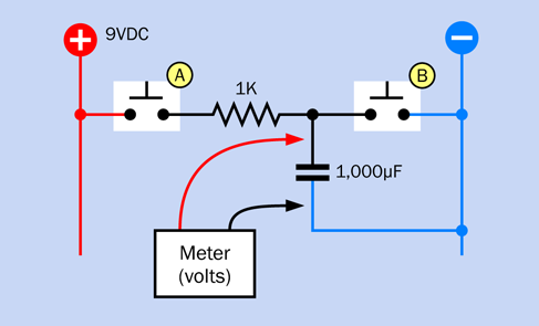
Figure 2-80. This schematic shows the same circuit as the preceding figure, which shows the breadboarded version.
The positive side of the capacitor has become “more positive” and the negative side has become “more negative” as electron-holes and electrons have been attracted to each other on the plates. The potential difference between the leads of the capacitor has increased, while current has not passed through it. One of the first statements you will find, when you read any introductory electronics text, is:
-
A capacitor blocks DC (direct current).
So long as you apply a steady electrical potential to the capacitor, this is true.
An RC Network
Remove the 1K resistor and substitute a 10K resistor. If the meter shows that there is still some voltage across the capacitor, discharge it by pressing button B.
Now repeat the test. How long does the capacitor take to reach 9.0V, charging through a 10K resistor?
This simple combination of a capacitor and a resistor is known as an RC network (R for resistor, C for capacitor). It’s a very important concept in electronics. Before I explain what it does, here are some questions to consider:
-
Did the capacitor take exactly 10 times as long to reach 9 volts when you used the 10K resistor instead of the 1K resistor?
-
Did the voltage across the capacitor rise at a steady rate, or did it increase faster at the beginning of the experiment—or toward the end?
-
If you wait long enough, will the capacitor ever reach the initial value that you measured as the voltage of your battery?
Voltage, Resistance, and Capacitance
Think of the resistor as a faucet restricting the flow of water, and the capacitor as a balloon that you are trying to fill (see Figure 2-81). If you screw down the faucet until only a trickle comes through, the balloon will take longer to fill. But a slow flow of water should still fill the balloon if you wait long enough. Assuming that the balloon doesn’t burst, the process will end when the pressure inside the balloon is equal to the water pressure in the pipe supplying the faucet.
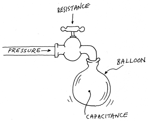
Figure 2-81. Water flowing into a balloon can be compared with electrons flowing into a capacitor.
But this description leaves out an important factor. As the balloon starts to fill, it stretches, exerting more pressure on its contents. As the pressure inside the balloon increases, it pushes back against the incoming flow of water. Consequently we may expect the water to flow in more slowly as the process continues.
How does this compare with electrons flowing into a capacitor? The concept is similar. Initially, the electrons go rushing in, but as they occupy more of the electron-holes, the newcomers take longer to find a resting place. The charging process gets slower, and slower. In fact, theoretically, the charge on the capacitor never quite reaches the voltage being applied to it.
Background: The Time Constant
The speed with which a capacitor charges is measured with a function known as the “time constant.” The definition is very simple:
T = R × C
where T is the time constant, in seconds, if a capacitor of value C (measured in farads) is being charged through a resistor of R ohms.
Going back to the circuit you first tested, using a 1K resistor, we can put the values of the components that you used into the time-constant formula—but only if we convert the units to ohms and farads. Well, 1K is 1,000 ohms, and 1,000µF is 0.001 farads. So the calculation becomes very easy:
TC = 1,000 / 0.001
Therefore, for those values of a resistor and a capacitor, TC = 1.
But what exactly does this mean? Does it mean that the capacitor will be fully charged in one second? Sorry, it’s not that simple.
-
T, the time constant, is the number of seconds required for a capacitor to acquire 63% of the voltage being supplied to it, if it starts with zero volts.
What if the capacitor doesn’t start from zero? If we start measuring after the capacitor has already acquired some voltage, the definition becomes a bit more complicated. If VDIF is the difference between the voltage on the capacitor and the supply voltage, T is the number of seconds required for a capacitor to add 63% of VDIF to its current charge.
(Why 63%? Why not 62%, or 64%, or 50%? The answer to that question is too complicated for this book, and you’ll have to read about time constants elsewhere if you want to know more. Be prepared for differential equations.)
A comparison may be helpful. Figure 2-82 shows a greedy guy who is ready to eat some cake. At first he’s ravenously hungry, so he takes 63% of the cake and eats it in one second, which is his time constant for eating cake. In his second bite, he takes another 63% of the cake that is left—and because he’s not feeling so hungry anymore, he requires one more second (remember, this is his time constant). In his third bite, he takes 63% of what still remains, and still ingests it in one second. And so on. He is gradually filling up with cake, like a capacitor filling up with electrons. But he never quite eats all the cake, because he only takes 63% of whatever is left.
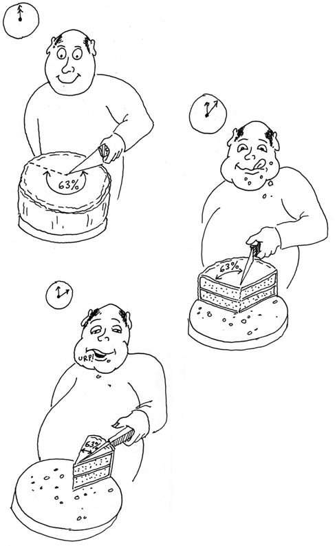
Figure 2-82. If our gourmet always eats just 63% of the cake still on the plate, he “charges up” his stomach in the same way that a capacitor charges itself. No matter how long he keeps at it, the cake is never quite gone and his stomach is never completely filled.
Figure 2-83 shows the process another way. After each time constant (which is one second, if we have a 1,000µF capacitor and a 1K resistor), the capacitor acquires another 63% of the difference between the charge it had and the voltage being applied.
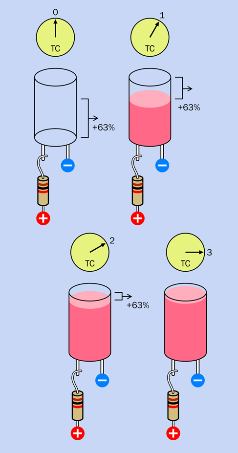
Figure 2-83. Another way of looking at a charging capacitor.
In a perfect world of perfect components, the charging process for a capacitor would continue for an infinite time. In the real world, we say rather arbitrarily:
-
After five time constants, the charge on the capacitor will be so close to 100 percent, we can think of the process as being complete.
Background: Graphing It
I want to draw a graph showing the voltage in a capacitor as it charges. To do this, I’m going to calculate the data by using the time-constant formula.
Suppose VCAP is the voltage on a capacitor right now, while VDIF is the difference between that amount of charge and the battery voltage being applied (as before). The formula shown below will tell me what the new voltage on the capacitor will be after one time constant. I’ll call the new voltage VNEW. The formula looks like this:
VNEW = VCAP + (0.63 × VDIF)
The 0.63 value is the same as 63 percent.
Suppose the battery was supplying exactly 9V and the capacitor started with exactly 0V. So, VCAP = 0 and VDIF = 9. Plug those values into the formula:
VNEW = 0 + (0.63 × 9)
My calculator tells me that 0.63 × 9 = 5.67. So after one time constant (one second, with a 1K resistor and a 1,000µF capacitor) the capacitor acquired 5.67 volts.
What about the next second? We have to repeat the calculation, using the new values. The current voltage on the capacitor, VCAP, is now 5.67. The battery is still applying 9V, so VDIF equals 9 minus 5.67, which is 3.33. We take those values back to the same formula:
VNEW = 5.67 + (0.63 × 3.33)
My calculator tells me that 0.63 times 3.33 equals 2.1, approximately. And 2.1 plus 5.67 equals 7.77. So, after two seconds, the capacitor has acquired 7.77 volts.
We can repeat this calculation any number of times, creating a sequence of numbers like this (rounded to two decimal places), showing the voltage on the capacitor at the end of each second, assuming a power supply of 9V:
After 1 second: 5.67 volts
After 2 seconds: 7.77 volts
After 3 seconds: 8.54 volts
After 4 seconds: 8.83 volts
After 5 seconds: 8.94 volts
After 6 seconds: 8.98 volts
The graph in Figure 2-84 was created by drawing a smooth curve through those values. I didn’t bother to go beyond six seconds, because the values climb so close to 9V.
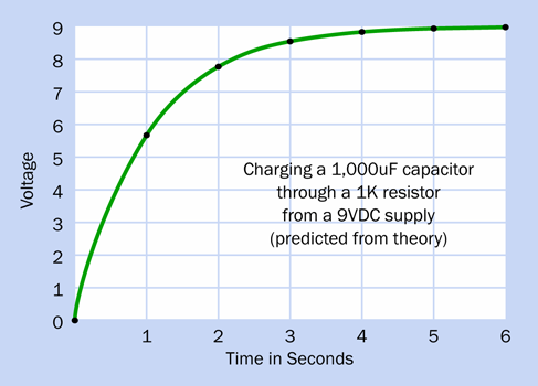
Figure 2-84. A graph can help to show how charge accumulates on a capacitor over a period of time.
Experimental Verification
I’ve told you how to calculate the charge on a capacitor in an RC network. But—how do you know I’m right? Should you just take my word for it?
Maybe you should test it yourself. In other words, you could do some experimental verification, which is a big part of Learning by Discovery.
Go back to the circuit that you used before, and make sure you have the 10K resistor in it, not the 1K resistor. Ask a friend to sit beside you, keeping track of the time, while you watch the display of volts on your multimeter. Every 10 seconds, your friend says “Now!” and you write down the voltage on the meter at that moment. You follow this procedure for one minute.
Because you’re using a 10K resistor, not a 1K resistor, the time constant is now 10 seconds instead of 1 second. So, your readings should look like the series of voltages that I tabulated above at 1-second intervals, except that yours will be at 10-second intervals.
The voltages that you measure should be close to mine, but they won’t match precisely. Why? I can think of many reasons.
-
Your battery doesn’t provide exactly the same voltage as mine.
-
Your resistor isn’t precisely 10,000 ohms.
-
Your capacitor is not exactly 1,000 microfarads.
-
Your meter is not totally accurate.
-
You will take a few microseconds to read the meter.
-
Your friend may not prompt you precisely every 10 seconds.
There are two other factors that you might not think of. First, capacitors don’t store electricity perfectly. They suffer from leakage, in which the charge gradually leaks away. This happens even while the capacitor is gaining charge. Toward the end of the charging process, the electrons are trickling in so slowly, the leakage (the rate at which they are trickling out) becomes significant by comparison.
Additionally, your meter has an internal resistance. It’s very high, but still, it’s there. This means that the meter is stealing a little bit of the charge from your capacitor while you are measuring the voltage. Yes, the process of making a measurement changes the value that you are trying to measure! This is actually a common problem in physics and engineering.
I can think of ways to minimize all of these factors, but I can’t imagine a way to eliminate them completely. There will always be some experimental error. This is the challenge when you use an experiment to verify a theory. Verification can be a very lengthy process, requiring a lot of patience—which is why theorists tend to have different personalities from experimentalists.
Capacitive Coupling
Now that I’ve told you how capacitors become charged and discharged, I have to go back to the statement I made before:
-
A capacitor blocks DC (direct current).
You may remember, I also said, “So long as you apply a steady electrical potential to the capacitor, this is true.”
But what if there isn’t a steady electrical potential? What happens at the moment when a capacitor goes from having no charge on it to connecting suddenly to a source of voltage?
Ahhh, that’s a different matter. Under those circumstances, the capacitor allows a signal to pass through.
How can this be? The plates inside a capacitor don’t touch each other, so, how can a pulse of electricity jump from one to the other?
I’ll deal with the “how” and “why” in a moment. First you need to make sure that what I’m talking about actually happens.
Take a look at the components on the breadboard in Figure 2-85. The layout is similar to the circuit in Figure 2-79, but the 10K resistor has moved from the left side to the right side, and an LED and a 470-ohm resistor have been added.
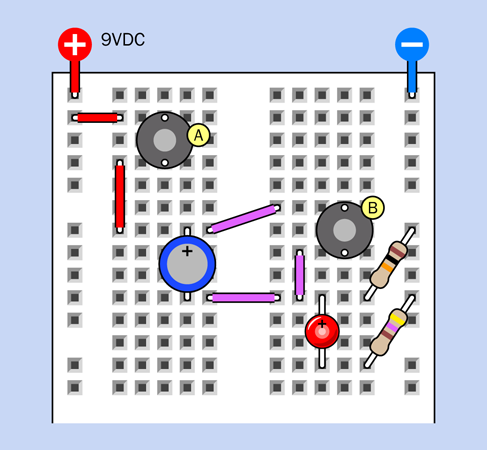
Figure 2-85. The flashing of a red LED shows how the behavior of a capacitor changes when there is a quick change in voltage.
The breadboarded circuit is redrawn as a schematic in Figure 2-86, which may help to clarify it.
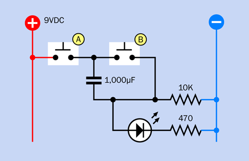
Figure 2-86. This schematic shows the same circuit as in the preceding figure depicting a breadboarded version.
And just to make sure there is no confusion, I’m showing the component values in Figure 2-87.
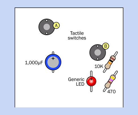
Figure 2-87. Component values for the breadboarded circuit.
After you assemble the circuit, first remember to press button B to discharge the capacitor. Now press button A, and—why did the LED just flash and slowly fade away?
Press button A again. This time, little or nothing happens. Evidently, the capacitor has to begin in a discharged state for this to work. So, press button B to discharge it. Now press button A again, and the LED flashes again.
We know that the capacitor started with almost no positive voltage on its lower pin, because it was connected to negative ground through the 10K resistor. We also know that the capacitor started with almost no positive voltage on its upper pin, because button B shorted both sides of the capacitor together. (That was why I asked you to discharge it.)
Then you pressed button A, which applied a sudden positive pulse, and the LED lit up on the other side of the capacitor. The current through the LED had to come from somewhere, and the only explanation is that it came through the capacitor.
Displacement Current
Let’s try this again, using your meter instead of the LED and its series resistor. Figure 2-89 shows the breadboard layout, while Figure 2-88 shows the schematic. Discharge the capacitor by pressing button B, and then check the reading on your meter. It should be near 0V.
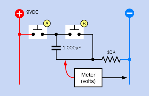
Figure 2-88. The schematic version of the preceding breadboarded circuit.
Watch your meter very carefully while you press button A. A digital meter does not respond very quickly, but still you will see a sudden rise in the voltage, after which the voltage gradually diminishes.
When I connected this circuit with an oscilloscope, which can measure and display very rapid changes in voltage, the trace looked look like the curve that I added at the bottom of Figure 2-89. The rise in voltage was so fast, it appeared to be instant.
The way that a capacitor allows a sudden fluctuation in voltage to pass through is well known, and is often used in electronics. But how can it happen?
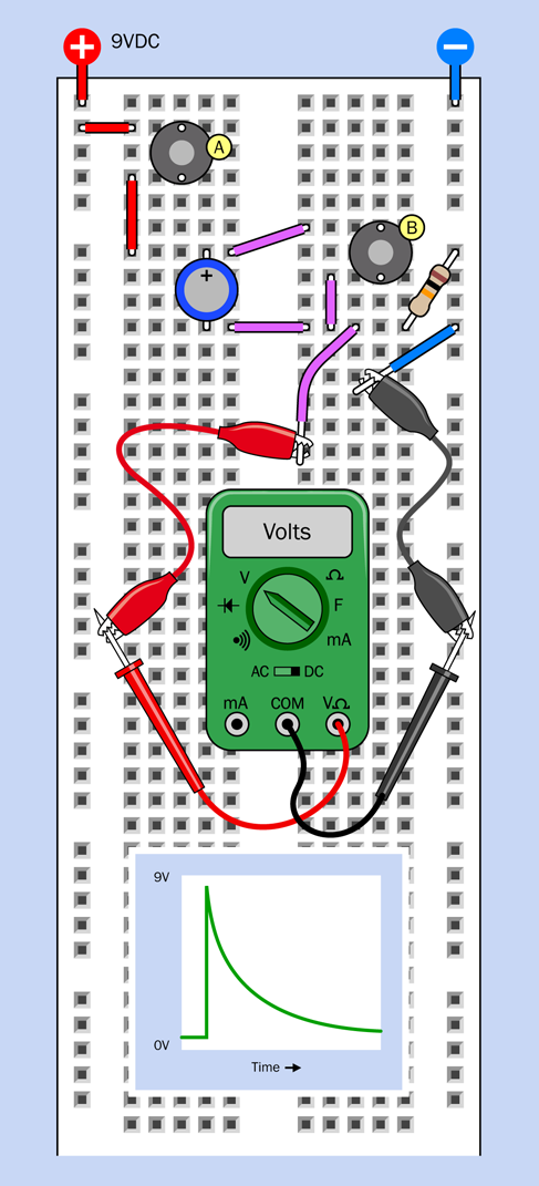
Figure 2-89. A meter has been substituted for the LED and 470-ohm series resistor that were used in the previous version of this circuit.
This question interested an early experimenter named James Maxwell, who felt it shouldn’t happen; so he developed a theory and invented a phrase to describe what he saw. He called it displacement current. This conformed with some theories that he was developing at the time.
Today, there are other theories. Apparently an inrush of current creates a field effect inside the capacitor, and the field effect can induce voltage on the opposite plate. But this concept becomes complicated very quickly, and most books simply say something like, “a capacitor will block DC but will pass fluctuations in voltage.”
If you substitute a smaller capacitor, you’ll find that it passes a briefer pulse. Remove the meter, put the LED and its 470-ohm resistor back into the circuit, and try 100µF, 10µF, 1µF, and 0.1µF capacitors. By the end of the series, the LED barely flickers.
Alternating Current
If you reverse the circuit, it still works, although current flows in the opposite direction. Figure 2-91 shows the circuit, with the 10K resistor moved to the left, and button A moved to the right. The meter still measures the voltage from the point between the resistor and the capacitor. The schematic in Figure 2-90 shows the same revision.
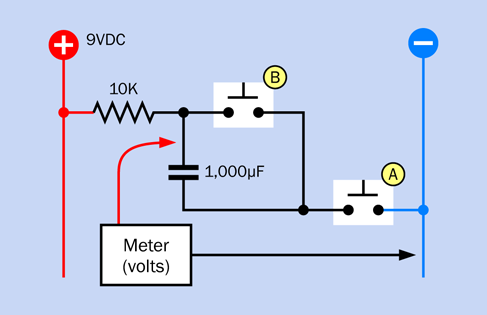
Figure 2-90. A schematic of the preceding breadboarded circuit.
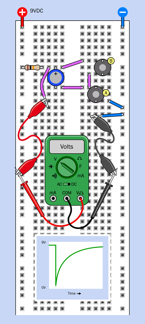
Figure 2-91. The previous circuit has been modified, with the voltages reversed.
After you press and release button B to discharge the capacitor, the meter measures approximately 9VDC, because the upper pin of the capacitor is connected with the positive bus through the 10K resistor. The capacitor is blocking DC, so it appears to have infinite resistance, and the positive charge has “nowhere to go.” This is illustrated in Figure 2-92, which shows how the voltage between a pair of resistors increases when the resistance increases between that point and ground.
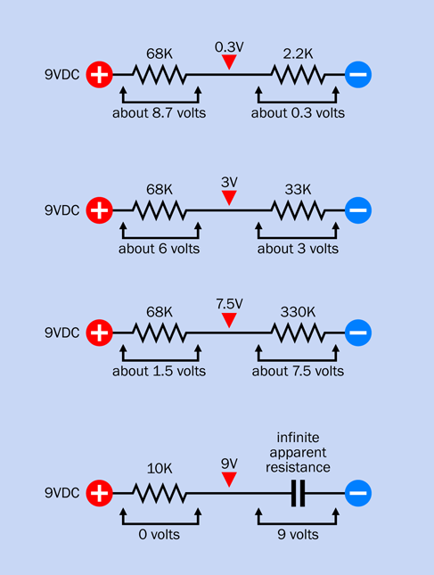
Figure 2-92. When you have a pair of resistors in series, and the left one is connected with the power supply while the right one is connected with negative ground, the voltage between the resistors increases as the value of the righthand resistor increases. A capacitor has an almost infinite effective resistance to DC current.
However, when you press button A in your breadboarded circuit, this creates a negative pulse. The effective resistance of the capacitor disappears momentarily as the pulse passes through, causing your meter reading to fall. Then the capacitor slowly recharges, just as it did in your very first test in this experiment.
The graph in Figure 2-91 gives a rough idea of how the charge on the capacitor changes.
-
A capacitor does block direct current (DC).
-
The same capacitor will allow a brief fluctuation to pass through, regardless of which way the current is flowing.
-
The capacitor then accumulates a charge, as I described at the beginning of this experiment.
This leads to an important conclusion. Because alternating current (AC) is a rapid series of relatively negative and relatively positive pulses, a capacitor will allow them through.
The size of the capacitor will be important. When you substituted smaller values, you saw that they would only respond briefly. A smaller capacitor will pass high-frequency fluctuations, but will block low-frequency fluctuations—and this behavior is useful in many applications, including audio. You’ll see this for yourself in Experiment 29. Bear in mind that audio signals are a form of alternating current, because they fluctuate rapidly.
When a capacitor is positioned in a circuit to pass AC while blocking DC, we call it a coupling capacitor. It can allow a signal to travel from one part of a circuit to another, while blocking their DC voltages, which can be completely different. I’ll be using this concept when we get to Experiment 11.
Experiment 10: Transistor Switching
Now that you’ve seen the behavior of capacitors, I’m going to move on to another fundamental component: the transistor. After you learn how that works, you’ll see how capacitors and transistors can be used together.
What You Will Need
-
Breadboard, hookup wire, wire cutters, wire strippers, multimeter
-
Transistor, 2N2222 (1)
-
9-volt battery and connector (1)
-
Resistors: 470 ohms (2), 1M (1)
-
Trimmer potentiometer, 500K (1)
-
Generic LED (1)
The Finger Test
I’m going to be using the 2N2222 transistor, which is the most widely used semiconductor of all time (it was introduced by Motorola in 1962 and has been in production ever since, in one form or another).
Because Motorola’s patents on the 2N2222 ran out long ago, any company can manufacture their own version of it. Some versions are packaged in a little piece of black plastic, while others are enclosed in a little metal “can.” I showed these two versions in Figure 2-23. For our purposes, either will do. However, note the warning that I included previously about part numbers (see “Essential: Transistors”). Some 2N2222s are not the same as others, and you need to use the right type.
Plug your transistor into your breadboard with an LED and a 470-ohm resistor, as shown in Figure 2-93. Make sure that the longer lead on your LED is facing to the left, as indicated by the + sign. Also, check that the transistor has its flat side facing to the right. In the unlikely event that you are using a transistor in a metal can, the tab sticking out from the can should point down and to the left.
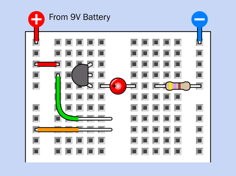
Figure 2-93. Breadboard setup for your first transistor test.
Notice that the wires that I have shown as green and orange have had some extra insulation removed. If you are using precut jumpers, you’ll have to bend out one leg of each, so that they rest flat on the breadboard.
Now for the fun part. Press your finger to the exposed metal of the green and orange jumpers as shown in Figure 2-94, while you watch the LED. If nothing happens, moisten your finger slightly and try again. The harder you press, the brighter the LED becomes. The transistor is amplifying the tiny amount of current flowing through your finger.
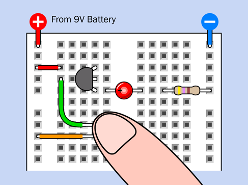
Figure 2-94. Adding your finger makes the experiment work.
Caution: Never Use Two Hands
The fingertip switching demo is safe if the electricity only passes through your finger. You won’t even feel it, because it’s 9 volts DC from a small battery. But it’s not a good idea to put the finger of one hand on one wire, and the finger of your other hand on the other wire. This would allow the electricity to pass through your body. Although there is no chance of hurting yourself in this circuit because the current is so small, you should never get into the habit of allowing electricity to run through you from one hand to the other. Also, when touching the wires, don’t allow them to penetrate your skin. This also means that you shouldn’t apply voltage to any body ornaments that already pierce your skin.
Inside the Finger Test
Take a look at Figure 2-95, which reveals the connectors inside the breadboard, omitting the ones that are not connected in this experiment. Notice that the bottom lead of the transistor is connected through the breadboard to the LED, and then through the 470-ohm resistor to the negative bus. So, enough current flowed out of the transistor to light the LED.
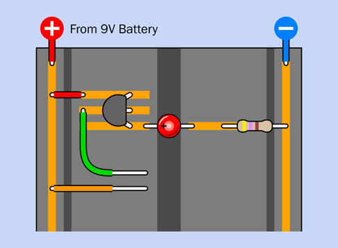
Figure 2-95. X-ray view of the breadboard from the previous figure.
Where did this current come from? Well, some electricity flowed in through the skin of your finger, to the center lead of the transistor. But this wasn’t enough to light an LED.
There’s only one other explanation. The transistor has a third lead, at the top, which is connected to the positive bus. Electricity entered the transistor through this lead. And then, somehow, this flow of current was controlled by the smaller amount of current that flowed through your finger into the center lead of the transistor.
This principle is illustrated in Figure 2-96.
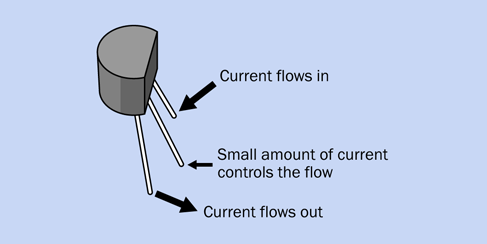
Figure 2-96. The basic function of an NPN transistor.
Incidentally, this phenomenon is very different from the behavior of the capacitor that you saw in the previous experiment. A capacitor just passed a quick pulse of electricity. A transistor controls a steady flow.
Fundamentals: Transistor Variants
The component that you’re using in this experiment is a bipolar transistor. It comes in two variants named NPN and PNP. The NPN type, which you have been using, contains three layers of silicon, of which two “N” layers have a surplus of negative charge carriers. A third layer, sandwiched between the other two, is the “P” layer, with a surplus of positive charge carriers. I won’t be going into a lot of detail about how the transistor works on an atomic level, because in this book I’m more interested in what a transistor does than in the theory that explains how it does it. You can find that information in any technical book, or in many sources online.
The three leads on an NPN bipolar transistor are named the collector, base, and emitter, as shown in Figure 2-97.
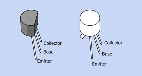
Figure 2-97. The names of the three leads of an NPN bipolar transistor, supplied in a plastic body (left) and metal can (right).
-
When the base of an NPN transistor is slightly more positive than its emitter, the transistor allows positive current to flow in through the collector and out through the emitter.
-
In this way, a very small current entering through the base of the transistor can control a larger current entering through the collector.
A PNP transistor functions oppositely to an NPN transistor. It allows negative current to flow in through the collector and out through the emitter when the base is slightly more negative than the emitter. PNP transistors are sometimes more convenient in a circuit, but are less commonly used. I will not be using them in Make: Electronics.
Four variants of the schematic symbol for an NPN transistor are shown in Figure 2-98. They all function the same way. The letters C, B, and E remind you that these connections are for the collector, base, and emitter.
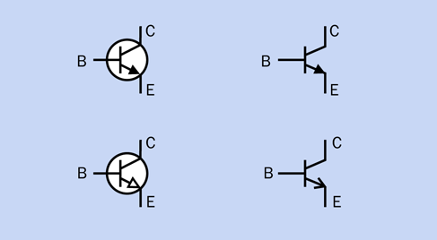
Figure 2-98. Any of these symbols may be used to represent an NPN transistor.
Four variants of the schematic symbol for a PNP transistor are shown in Figure 2-99. They all function the same way.
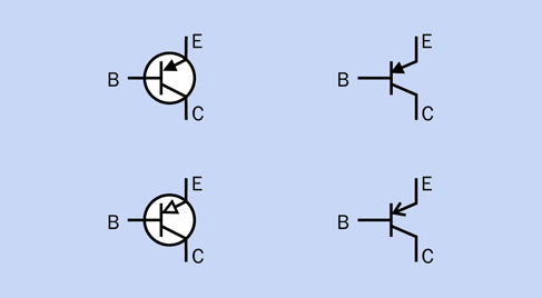
Figure 2-99. Any of these symbols may be used to represent a PNP transistor.
It’s easy to get the symbols for PNP and NPN transistors mixed up, but there’s a simple way to remind yourself which is which. The arrow in the NPN symbol points outward, never in. So, think of “NPN” as being short for “never pointing in.”
Adding a Potentiometer
To learn more about the way in which a transistor works, we need a component that is a little more controllable than the tip of your finger. I think a potentiometer will do the job, but not the large type that you used previously. A trimmer potentiometer is what I have in mind, as pictured in Figure 2-22.
Even though they are dissimilar in shape and size, they all have three pins. These pins are functionally the same as the three tags that stick out of a large potentiometer of the kind that you used previously. The middle pin always connects with the wiper inside the trimmer, while the other two pins connect with each end of the resistive track inside it. Here is the basic rule that you must always follow:
-
When you plug a trimmer into your breadboard, each pin must connect with a separate row of holes on the breadboard.
This rule is illustrated in Figure 2-100. At the top of the figure I have drawn a plan view of three types of trimmers, including the multi-turn type, because even though I am not recommending it, you may find yourself using one, some day. The pins are not visible from above, but I have shown their positions as if you can see them through the component. The positioning varies, but there are always three pins, and they should be 1/10” apart vertically.
In the lower part of the figure, the two “Yes” examples will work because each pin connects with a different row of holes in the breadboard. The two “No” examples are unacceptable, because a pair of pins will be shorted together by a conductor inside the board.
Having dealt with the trimmer basics, I want you to add a 500K trimmer to your transistor circuit. This is shown in Figure 2-101. Connect the power and use a small screwdriver to rotate your trimmer all the way clockwise, and all the way counterclockwise. Notice that if you start with the LED completely dark, you have to turn the screw on the trimmer a little way before the LED begins to glow.
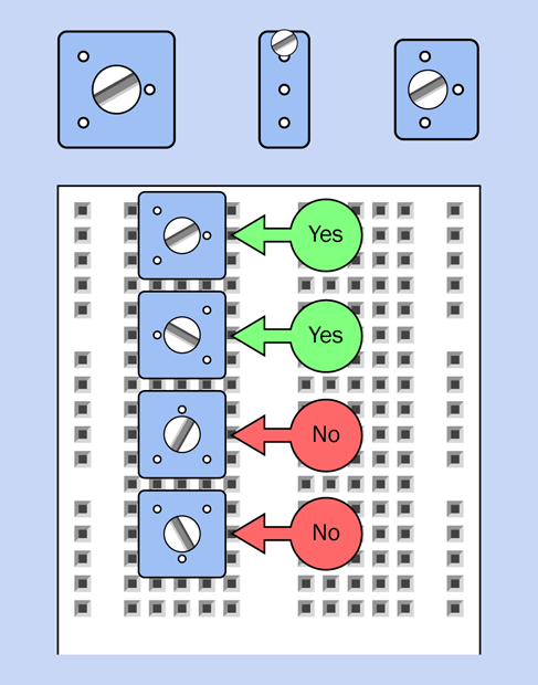
Figure 2-100. Three types of trimmers, and the correct orientation of their pins.
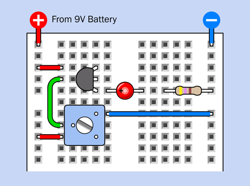
Figure 2-101. The previous circuit now has a trimmer potentiometer so that you can control the transistor more precisely than was possible with your finger.
Take a look at the schematic in Figure 2-102, which shows the same connections that you made on the breadboard, but in a format that is easier to understand.
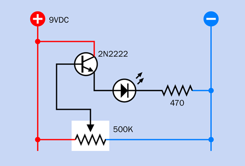
Figure 2-102. This schematic shows the same breadboard circuit that you built using a trimmer.
The component values are also shown in Figure 2-103.
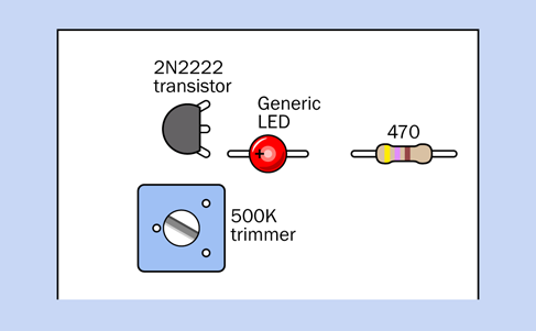
Figure 2-103. Values for the breadboarded components.
The potentiometer is connected between the positive bus and the negative bus. In this orientation we call it a voltage divider. When the wiper is at one end of the track, it connects directly with the positive side of the power supply. At the other end of the track, it connects directly with negative ground. At positions in between, it divides the voltage. Potentiometers are often used in this way, to provide a full range of voltages.
I mentioned that the LED didn’t light up when you first started moving the wiper of the potentiometer from negative to positive. Is this just because the LED isn’t getting enough power? Not exactly. The bipolar transistor deducts some of the power as its fee for providing a service. It won’t respond unless the voltage at its base is higher than the voltage at its emitter (usually by around 0.7V). In this mode, the transistor is positively biased.
The general concept is illustrated in Figure 2-104.
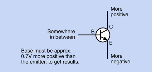
Figure 2-104. Rule of thumb for using an NPN transistor.
Voltage and Current
You’ve seen that the voltage at the base of a bipolar transistor controls the output from the transistor. Does that mean the transistor is amplifying the voltage?
You can discover this for yourself. Take your meter, set it to measure volts, and use a test lead to anchor the negative probe to the negative bus on the breadboard, as shown in Figure 2-105. Touch the red probe to the emitter pin of the transistor, make a note of the voltage, and move the probe to the base pin. I guarantee that the voltage at the emitter will be lower than the voltage on the base.
Readjust the trimmer to a different position, and try again. Regardless of how you change the voltage on the base pin, the emitter pin will always be lower.
Could this be because the 470-ohm resistor doesn’t provide much resistance between the emitter of the transistor and the negative bus? Could it be pulling the voltage down?
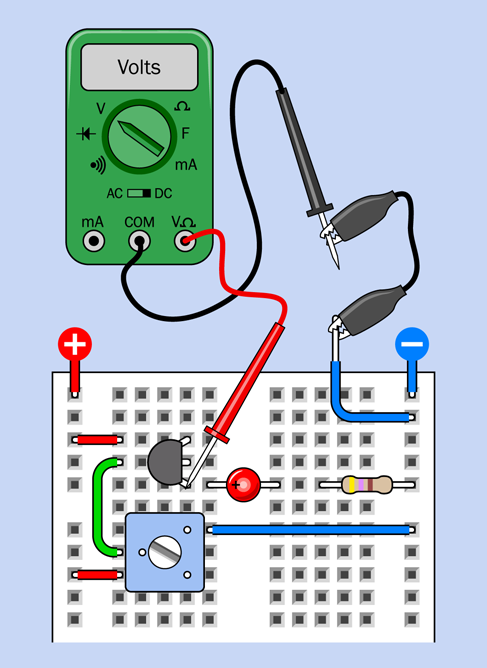
Figure 2-105. Testing to discover if a transistor amplifies voltage.
Let’s find out. Remove the LED and the 470-ohm resistor, and substitute a 1M resistor between the emitter of the transistor and negative ground. It won’t make much difference. The voltage on the emitter will still be lower than the voltage on the base.
If you have the patience to test the current into the base and out of the emitter, you would find something very different. This would entail setting your meter to measure milliamps and inserting it into the circuit in each location. Remember, current must pass through the meter to be measurable.
But I’ll tell you what you would find. This particular transistor amplifies the current entering its base by a factor of more than 200:1. This is called the beta value of a transistor, and leads me to a fundamental fact:
-
A bipolar transistor amplifies current, not voltage.
In Make: More Electronics you can find a lot more on this topic. I’m keeping it brief, here, because this is an introductory book.
Now I’ll summarize the facts about bipolar transistors, for your future reference.
Fundamentals: All About NPN and PNP Transistors
A transistor is a semiconductor, midway between being a conductor and an insulator. Its effective internal resistance varies, depending on the power that you apply to its base.
All bipolar transistors have three connections: Collector, Base, and Emitter, abbreviated as C, B, and E on the manufacturer’s data sheet, which will identify the pins for you.
-
NPN transistors are activated by positive voltage on the base relative to the emitter.
-
PNP transistors are activated by negative voltage on the base relative to the emitter.
In their passive state, both types block the flow of electricity between the collector and emitter, just like an SPST relay in which the contacts are normally open. (Actually a transistor allows a tiny bit of current known as leakage.)
In a schematic, the orientation of a transistor may vary. The emitter may be at the top and the collector at the bottom, or vice versa. The base may be on the left, or on the right, depending on what was most convenient for the person drawing the schematic. Be careful to look at the arrow in the transistor to see which way up it is, and whether the component is NPN type or PNP type. You can damage a transistor by connecting it incorrectly.
Transistors come in many different sizes and configurations. In a lot of them, there is no way to tell which wires connect to the emitter, the collector, or the base. You may need to check the manufacturer’s datasheet to find out.
If you forget which lead is which, many multimeters have a function that will identify the emitter, collector, and base for you. Typically there are four holes labeled E, B, C, and E. When you have the emitter lead of your transistor inserted in either of the holes marked E, the base lead in B, and the collector lead in C, the meter will display the beta value of the transistor. In any other orientation, the meter reading will be unstable, or blank, or zero, or much lower than it should be (almost always below 50, and usually below 5).
Caution: Fragile Component!
Transistors are easily damaged, and the damage will be permanent.
-
Never apply a power supply directly between any two pins of a transistor. You can burn it out with too much current.
-
Always limit the current flowing between the collector and the emitter of a transistor by using another component such as a resistor, in the same way you would protect an LED.
-
Don’t apply voltage in reverse orientation. The collector of an NPN transistor should always be more positive than the base, which should be more positive than the emitter.
Background: Transistor Origins
Although some historians trace the origins of the transistor back to the invention of diodes (which allow electricity to flow in one direction while preventing reversal of the flow), the first practical and fully functional transistor was developed at Bell Laboratories in 1948 by John Bardeen, William Shockley, and Walter Brattain.
Shockley was the leader of the team, and had the foresight to see how potentially important a solid-state switch could be. Bardeen was the theorist, and Brattain actually made it work. This was a hugely productive collaboration—until it succeeded. At that point, Shockley started maneuvering to have the transistor patented exclusively under his own name. When he notified his collaborators, they were naturally unhappy about this.
A widely circulated publicity photograph didn’t help, in that it showed Shockley sitting at the center in front of a microscope, as if he had done the hands-on work, while the other two stood behind him, implying that they had played a lesser role. A copy of this picture appeared on the cover of Electronics magazine (see Figure 2-106). In fact Shockley, as the supervisor, was seldom present in the laboratory where the real work was done.

Figure 2-106. Front, William Shockley. Rear, John Bardeen. Right, Walter Brattain. For their collaboration in development of the world’s first working transistor in 1948, they shared a Nobel prize in 1956.
The productive collaboration quickly disintegrated. Brattain asked to be transferred to a different lab at AT&T. Bardeen moved to the University of Illinois to pursue theoretical physics. Shockley eventually left Bell Labs and founded Shockley Semiconductor in what was later to become Silicon Valley, but his ambitions outstripped the capabilities of the technology of his time. His company never manufactured a profitable product.
Eight of Shockley’s coworkers in his company eventually betrayed him by quitting and establishing their own business, Fairchild Semiconductor, which became hugely successful as a manufacturer of transistors and, later, integrated circuit chips.
Fundamentals: Transistors and Relays
One limitation of NPN and PNP transistors is that they require power to perform their function, unlike a relay, which can be passively on or off without any power input at all.
Relays also offer more switching options. Different versions can be normally open, normally closed, or can latch in either position. A relay can contain a double-throw switch, which gives you a choice of two “on” positions. It can also contain a double-pole switch, which makes (or breaks) two entirely separate connections. Single-transistor devices cannot provide the double-throw or double-pole features, although you can design more complex circuits that emulate this behavior.
A table comparing the attributes of transistors and relays appears in Figure 2-107.
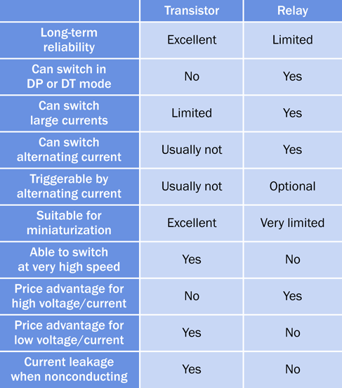
Figure 2-107. Principal attributes of relays and transistors, compared.
The decision to use a relay or a transistor will depend on each particular application.
So much for the theory. Now what can we do with a transistor that’s fun, or useful, or both? We can do Experiment 11!
Experiment 11: Light and Sound
It is time now for your first project that has a function and a purpose. It will culminate with an ultra-simple sound synthesizer.
What You Will Need
-
Breadboard, hookup wire, wire cutters, wire strippers, multimeter
-
9-volt battery and connector (1)
-
Resistors: 470 (2), 1K (1), 4.7K (4), 100K (2), 220K (2), 470K (4)
-
Capacitors: 0.01µF (2), 0.1µF (2), 0.33µF (2), 1µF (1), 3.3µF (2), 33µF (1), 100µF (1), 220µF (1)
-
Transistors: 2N2222 (6)
-
Generic LED (1)
-
Loudspeaker, 8-ohm, 1” or (preferably) 2” (1)
Fluctuations
Figure 2-108 shows the new circuit that I’d like you to create on your breadboard. There’s not a lot of room among the components, so you may find that it’s easier to install them using your pliers instead of your fingers. Count the holes in the board carefully, and double-check to make sure that everything is in exactly the right place.
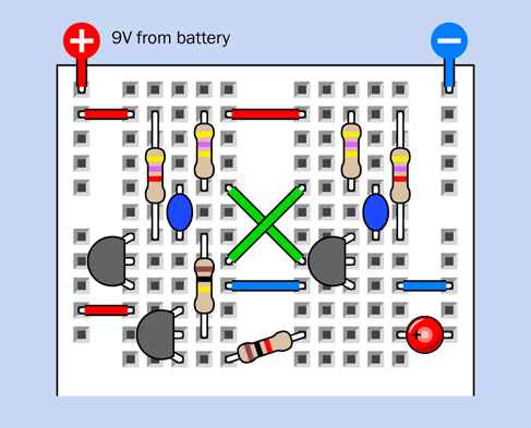
Figure 2-108. Breadboard layout for an oscillator circuit.
The component values are shown in Figure 2-109.
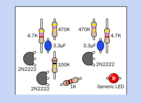
Figure 2-109. Component values in the breadboarded circuit.
Apply power, and the LED should flash on for approximately one second, and off for approximately one second.
Is that all? No, we’ve just begun. First, however, you have to understand how it works. Check the layout in Figure 2-110 if you have difficulty visualizing how the components are connected inside the board. Then look at the schematic in Figure 2-111, and you’ll see that the connections between components are the same. I’m going to be using the schematic to explain what’s going on.
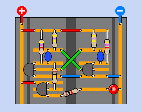
Figure 2-110. This x-ray view may help to elucidate the interconnections between components.
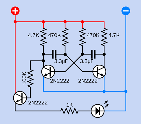
Figure 2-111. The components in this schematic are in similar locations in the breadboard layout.
The first thing you’ll notice is that it is somewhat symmetrical. Does that mean that the left half and the right half are both doing the same thing? Yes, but not at the same time. In effect, one half turns the LED on, and the other half turns it off.
Understanding this in detail is tricky, because the voltages are constantly fluctuating, and more than one thing is happening at any given moment. However, I have created four snapshots showing the inner workings at intervals, and I’m hoping they will make everything clear.
I have omitted the third transistor and the LED from each snapshot, as they have no role in creating the oscillation in the circuit.
The first snapshot is in Figure 2-112. I have color-coded the wires like this:
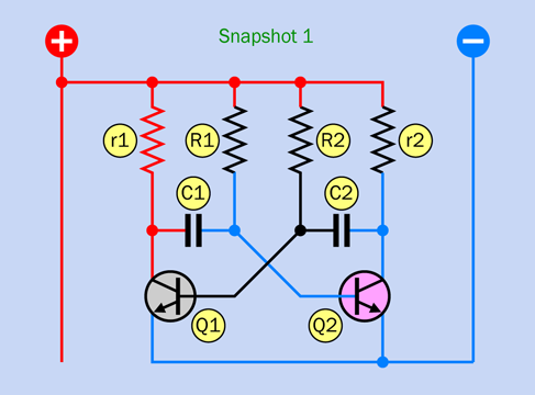
Figure 2-112. The first of four snapshots showing voltages in the LED-flasher circuit. See text for details.
-
Black conductors and components have an unknown or indeterminate voltage.
-
Blue conductors are at a near-zero voltage.
-
Red conductors are rising toward positive supply voltage.
-
White conductors are briefly pulled down to a more negative voltage (below negative ground), for reasons I’ll get to in a moment.
As for the transistors:
-
A gray transistor is not conducting electricity from collector to emitter. You can think of it as “switched off.”
-
A pink transistor is conducting.
The transistors are labeled Q1 and Q2, because this is a common way to identify semiconductors. The little tab sticking out of an old-fashioned metal-can transistor made it look like a letter Q when seen from above, and people got into the habit of identifying transistors this way.
To distinguish between the two sides of the circuit, r1 and R1 are on the left, and r2 and R2 are on the right. Lowercase letters identify the lower-value resistors.
One last note before I begin the explanation. Bear in mind the fundamental behavior of a transistor:
-
When current into its base switches it “on,” its effective internal resistance drops very low. Consequently, if its emitter is grounded at approximately 0 volts, its collector will also be near 0 volts, and so will anything connected directly to the collector. The base can also be at a relatively low voltage, so long as it is not quite as low as the emitter. You can see this happening to Q2 in Snapshot 1.
-
When it switches “off,” the effective internal resistance of the transistor rises to at least 5K. Consequently, any component attached to its collector isn’t grounded through the transistor anymore, and can accumulate a positive charge.
Step by Step
I’m going to begin at an arbitrary moment while the circuit is already running. After I proceed through the sequence of events, I’ll get to the issue of how it begins to oscillate initially.
In Snapshot 1, let’s suppose that Q1 has just switched off and Q2 has just switched on. The bottom end of r1 was being grounded through Q1, but now that Q1 is off, the voltage on its collector starts to rise, and this increases the voltage on the left side of C1. The voltage on the base of Q1 also starts to rise, but not as rapidly, because R2 has a higher value. Meanwhile, because Q2 is on, it is sinking current from r2, pulling the voltage down. The base of Q2 is also sinking current through the transistor to negative ground.
That’s the setup. What next?
In Snapshot 2, shown in Figure 2-113, the voltage on the base of Q1 increased enough to start it conducting. It is now sinking current from C1 and also through its base, which is why those wires are now blue. The sudden change in the voltage on the left side of C1 momentarily induces an equal drop on its righthand side, as a result of the field effect that can also be described as displacement current, described in Experiment 9. This actually pulls the voltage on the righthand side of C1 below zero, represented by the white wire. This immediately switches off Q2 by inflicting negative bias on its base.
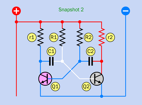
Figure 2-113. The second snapshot.
In Snapshot 3, shown in Figure 2-114, Q1 is still switched on while Q2 is still off. This is the mirror image condition of Snapshot 1. C1 has started to charge in the opposite direction, through R1. Gradually this is increasing the voltage on the base of Q2.
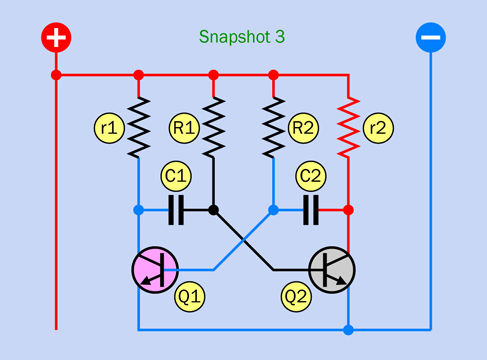
Figure 2-114. The third snapshot.
In Snapshot 4, shown in Figure 2-115, Q2 has started conducting, grounding the right side of C2. This transition pulls down the voltage of the left side of C2 below zero, and switches off Q1 by grounding its base. This is the mirror image of Snapshot 2.
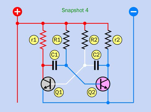
Figure 2-115. The fourth snapshot. After this, the sequence repeats.
After the fourth snapshot, the sequence repeats from Snapshot 1. If the extra transistor and LED are connected as in Figure 2-111, the LED should light up during snapshots 1 and 4.
Coupling Capacitor
As you can see, oscillators can be difficult to understand. This particular circuit is extremely common. In fact, if you search Google Images for “oscillator,” this is probably what you’ll find. Still, many people have difficulty with it.
The key is that in Snapshots 2 and 4, a sudden voltage drop on one side of a capacitor creates an equal voltage drop on the other side—the coupling effect that you saw for yourself in Experiment 9.
But How Does It Start?
Bear in mind that the circuit is basically symmetrical. When you first power it up, why shouldn’t both of the transistors be on, or both of them off?
In a perfect world, where two transistors or two resistors can be absolutely identical, the circuit would initialize itself symmetrically. But in reality, there’s always a tiny manufacturing difference among resistors and capacitors, causing one transistor to start conducting before the other. As soon as that happens, the circuit is out of balance, and it starts to oscillate as I described above.
Another issue to explain would be, how did I decide where to take an output from the oscillator circuit? In the original schematic, notice that r1 and r2 have much lower values than R1 and R2. This will allow the left side of C1 to charge quickly, almost to the full value of the supply voltage—and the right side of C2 behaves the same way. So, we can get a nice wide voltage range from either of those locations. I chose the one on the left, simply because it enabled an easier layout of additional components in the schematic.
If the circuit is tapped for too much current, this will slow down the process of charging the capacitor, and will affect the timing and balance of the oscillator. Therefore, I fed the signal through a 100K resistor to the base of another transistor. That transistor will draw very little current through its base but will amplify the signal so that you can do something useful with it.
Why So Complicated?
In the first edition of this book, I suggested a flashing-LED project using a component called a Programmable Unijunction Transistor (PUT). Its behavior is much easier to understand, and you only need one of them to get a result. But PUTs are not used much anymore, and some readers complained that you can’t buy them easily, while others said that using a PUT was just too old-school.
Really you can still buy PUTs, but they are almost obsolete. Bipolar transistors are still widely used, so I listened to my reader feedback and abandoned the PUT. I considered various alternative oscillator schematics before settling on this one, mainly because this circuit is more common than any of the others. Also, I think all oscillator circuits can be somewhat difficult to understand.
A Processed Pulse
You’ve learned that two transistors can create a signal that pulses on and off, and a third transistor can amplify it to power an LED. Think back for a moment to the previous experiments. What have you learned from them that you might be able to apply to this one?
We have an output that is fluctuating quite slowly. So, we can make it more interesting by adding an RC network. (See “An RC Network” if you need to refresh your memory regarding this concept.)
Take a look at Figure 2-116. The new RC section is at the bottom.
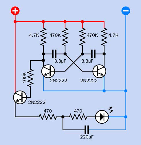
Figure 2-116. The previous schematic has been modified with one additional resistor and a 220µF capacitor at the bottom, making an RC network.
In Figure 2-117 the components that have been added or repositioned are in color at bottom-right, while the components that are unchanged have been grayed out.
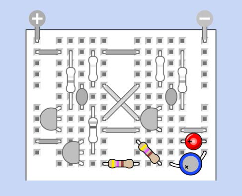
Figure 2-117. Components in color have been added or repositioned. The new capacitor is a 220µF electrolytic.
Now when you run the circuit, the LED pulses gently instead of flashing on and off. Can you see why? The capacitor charges through the first 470-ohm resistor, then discharges through the other. Why does this matter? Well, let’s suppose you were thinking of making some electronic jewelry. Adjusting the way that it flickers or pulses could be an important aesthetic factor. On old Apple laptops, the logo used to pulse instead of flashing.
Upping the Speed
What else can you do with this circuit? You can easily adjust the speed. Remove the two 3.3µF capacitors, and substitute two 0.33µF capacitors. They should charge about 10 times faster, so the LED should flash 10 times faster, too. Is that what happens?
What if you reduce the capacitor values even more, to 0.01µF? Beyond 50 flashes per second, you have moved from a frequency that you can see to a frequency that you can hear.
How can you change the output of this circuit to be audible instead of visible? Easily! Remove the LED, the 470-ohm resistors, and the 220µF capacitor, and substitute a little loudspeaker, a 100µF coupling capacitor, and a 1K resistor as shown in Figure 2-118. The resistor grounds the emitter of the transistor, because a transistor will only work if its emitter has a defined voltage lower than the voltage at its base. The capacitor blocks the DC component of the signal, while allowing the alternating current through. In the schematic, I only included the parts that have changed. How should they be installed on the breadboard? I think you can figure that out.
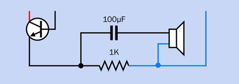
Figure 2-118. Modifying the circuit to generate audio.
Still More Mods
Now that you have sound, how about raising the pitch of the sound? Just substitute smaller resistors or capacitors in the oscillator circuit. You could remove the 470K resistors and substitute 220K resistors (or a value in between). Transistors can switch a signal more than a million times per second, so you certainly won’t push their limits by making your oscillator run faster. A signal that oscillates 10,000 times per second sounds extremely high-pitched. If you push it to 20,000 times per second, it’s above the hearing range of almost all human ears.
How about changing the character of the sound?
In the upper half of Figure 2-119 I’ve substituted a 1µF coupling capacitor in series with the loudspeaker, instead of the 100µF capacitor that was there previously. The lower value for the capacitor will only pass high frequencies (short pulses), and will deprive the sound of some of its lower resonance.
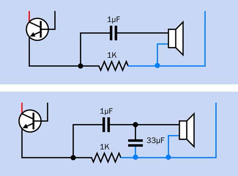
Figure 2-119. Substituting a smaller value for the coupling capacitor blocks the lower audio frequencies, so that you only hear the higher frequencies. Placing a capacitor so that it bypasses the speaker reroutes the higher frequencies to negative ground, so that you only hear the lower frequencies.
What if you put a capacitor across the loudspeaker, as shown in the lower part of Figure 2-119? Now the opposite effect occurs, because the capacitor is still passing higher frequencies, but routes them past the loudspeaker. In this orientation, you have a bypass capacitor.
These are all simple ways to modify a circuit. If you feel a little more ambitious, you could duplicate the circuit and use one section to control the other.
Restore the original component values from Figure 2-109, so that it runs at the slow original speed. Then use its output to power the duplicate section below it on the breadboard with 0.01µF capacitors to generate an audio frequency. This is shown in Figure 2-120, where the part that you built originally in this project has been grayed out, and the audio section is at the bottom.
The red piece of wire labeled A has been repositioned so that the lower section of the circuit now gets its power from the output of the upper section. The red and blue wire segments labeled B have been added to bridge the gaps that you may have in the buses of your breadboard.
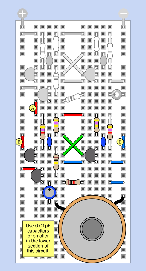
Figure 2-120. Driving the audio section of the circuit by using a slower-running duplicate to provide fluctuating power.
What happens if you change the capacitor or resistor values in the top half of the circuit, to switch the bottom half faster?
What would happen if you take a 220µF capacitor and apply it between various points (either in the top half of the circuit, or the bottom half) and negative ground? You won’t damage any components, so feel free to experiment.
Another option is to go back to the “processed pulse” of light created in Figure 2-116, and change the way in which the components are physically joined together. You can remove them from the breadboard and rebuild them into a small wearable object.
I’m going to show you how to do that in Experiment 14. Of course, this will entail some soldering, but learning to solder components together is what I want you to do in Experiment 12, which is next.
Background: Mounting a Loudspeaker
Figure 2-121. A paper or cardboard tube increases the perceived volume from a loudspeaker.
The diaphragm of a loudspeaker, also known as its cone, is designed to radiate sound. However, as it oscillates up and down, it emits sound from its back side as well as its front side. Because the sounds are opposite in phase, they tend to cancel each other out.
The perceived output from a loudspeaker can increase dramatically if you add a horn around it in the form of a tube that focuses the output from the front. For a miniature 1-inch loudspeaker, you can bend and tape a large file card around it. See Figure 2-121.
Better still, mount it in a box with holes drilled in it to allow sound from the front of the speaker to radiate, while the closed back side of the box absorbs sound from the rear of the speaker.