Offshore wind turbines
Puyang Zhang State Key Laboratory of Hydraulic Engineering Simulation and Safety, Tianjin University, Tianjin, China
Abstract
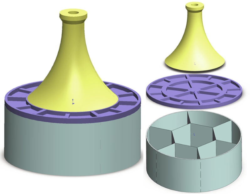
The composite bucket foundation (CBF) is a new type of offshore wind turbines, which can be adapted to the loading characteristics and development needs of offshore wind farms due to its special structural form. There are seven rooms divided inside the CBF by steel bulkheads, which are arranged in a honeycomb structure. The six peripheral rooms with the skirt have the same proportions, while the middle orthohexagonal one is a little larger. The large bending moment and horizontal force of the wind turbine tower are transferred to and dispersed into the sea floor soil through a prestressed curved concrete transition section, the head cover of the bucket foundation, the sidewalls of the bucket foundations, and the internal steel compartment plates. With the seven-section structure, the CBF has reasonable motion characteristics and towing reliability during the wet-tow construction process. Moreover, the pressure inside the compartments can control the levelness of the CBF during suction installation.
Keywords
Composite bucket foundation (CBF); Force transfer characteristics; Bearing capacity; Suction; Offshore wind turbine
11.1 Introduction
The foundation of an offshore wind turbine unit consists of a tower frame and a seafloor foundation. In China, the mono pile, three-pile tripod foundation, multipile jacket foundation, and multipile cap foundation are typical foundations (see Fig. 11.1) for offshore wind turbines, which can effectively convert loads and improve the overturning resistance (high-pile cap foundation, 2010; multi-piles foundation, 2013; high socketed pile cap foundation, 2015; Longyuan Zhenhua No. 2, 2012). A research group led by Professors Lian and Ding at Tianjin University and DaoDa Offshore Wind Company innovated a new foundation based on the conventional bucket foundation and, for the first time, proposed a composite bucket foundation (CBF, shown in Fig. 11.2) and one-step installation technique for offshore wind turbines suitable for the marine area offshore of China. This proposed structure effectively converts the extremely large bending moment of the turbine tower to limited tensile and compressive stresses within the foundation structure via a transition section; in addition, the proposed structure effectively solves the deformation compatibility and cracking control problems of steel-concrete structures via prestressing and makes full use of the properties of the material (Ding et al., 2013, 2015a,b; Lian et al., 2014, 2012a,b, 2011; Liu et al., 2015a,b; Zhang et al., 2013a,b, 2013c,d, 2014a,b, 2015).
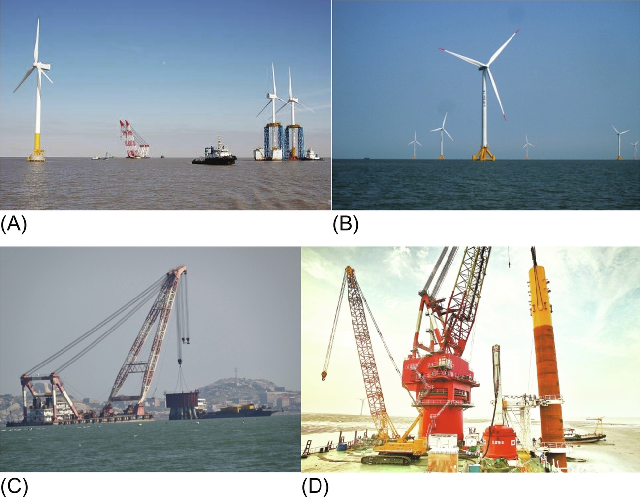
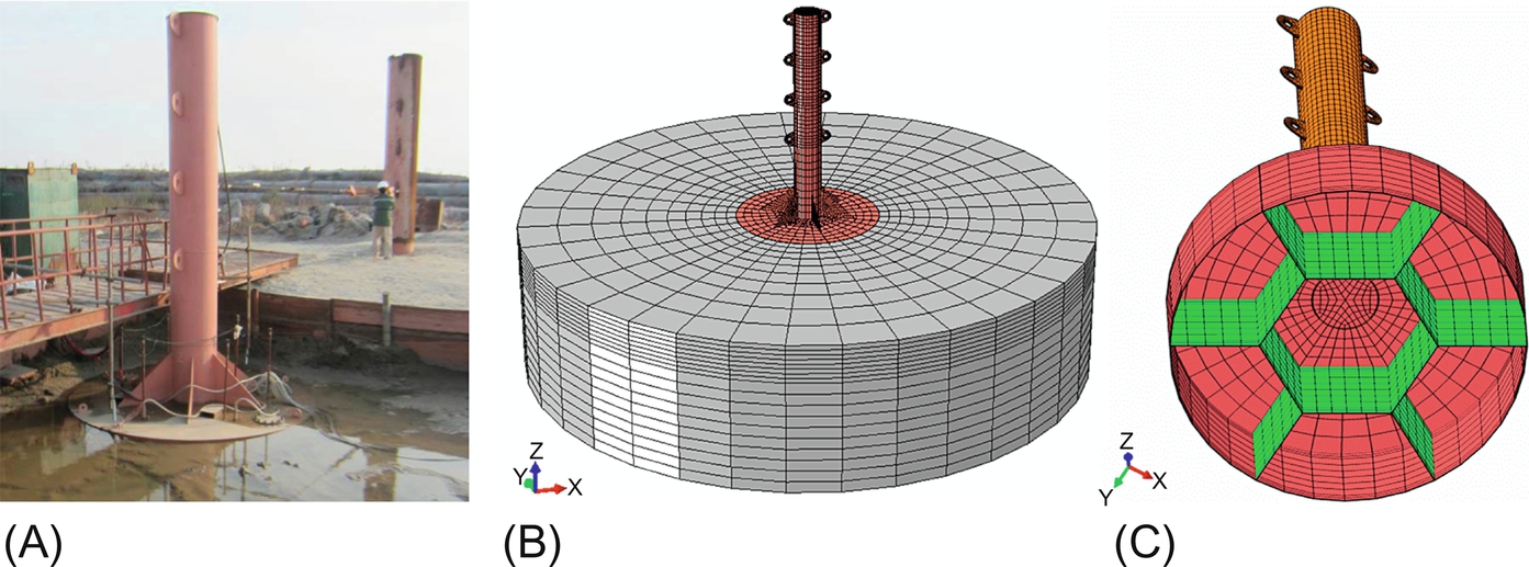
In 2010, the first composite BFB (Bucket Foundation with Bulkheads) for offshore wind turbines was successfully installed at the offshore test facility in Qidong City, China, as shown in Fig. 11.3A. In 2016, two BFBs were also installed in Xiangshui City, China (see Fig. 11.3B). At the same time, a series of tests were conducted on the prototype, including a structural test under construction conditions, a static test after the installation was complete, a dynamic test after the installation was complete, and a sinking test under simulated large bending-moment working conditions. The development of core techniques for the CBF and the construction of offshore wind turbines address the constraints of large-scale development of offshore wind power in China. The three primary core techniques are as follows: (1) a new prestressed steel strand steel plate concrete composite bucket wind turbine foundation structure system is proposed; the system displays certain force transfer characteristics and stress distributions; (2) the modeling and calculation of the bearing capacity of the ground for the large-scale CBF with the bucket head cover as the main load-bearing component have been established, and the limitations of other foundation structures in soft ground are thereby overcome; (3) the “floating transport-sinking-leveling” construction technique is proposed for the composite bucket offshore wind turbine foundation structure.

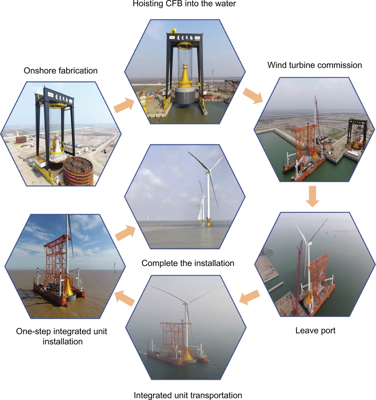
Based on the characteristics of the CBF (no pile needs to be driven for the entire structure, there is no impact load, and negative-pressure sinking is unnecessary for installing the CBF), an innovative special construction vessel has been designed to replace the hoisting vessel to install offshore wind turbines. This special construction vessel can be used to provide integrated transportation and one-step installation. Similar to planting trees in the ground, the special construction vessel can be used to “plant” wind turbines in the seabed. The one-step installation technique developed by our team achieves complete wind turbine structure installation. The proposed scheme (see Fig. 11.4) has seven primary aspects: the prefabrication of the foundation, the floating transport of the foundation, the assembling of the wind turbine on land and the testing of the complete wind turbine unit, the floating transport of the complete wind turbine unit, the on-site one-step installation, consignment, and recycling of the unit. Compared with conventional wind turbine installation, the primary advantage of the one-step installation technique is the assembly of the wind turbine on land, which avoids the use of large equipment in the marine environment, reduces the installation difficulty, is easier, improves the installation quality and structural reliability, reduces the risk of damage to the components of the wind turbine resulting from the offshore construction environment and technical limitations to a certain degree, and reduces the investment costs of various construction steps. The one-step installation technique allows for rapid offshore construction. In addition, the technique is safe, economical, and efficient and can allow for the recycling and reuse of the wind turbine and the foundation structure. The technique also supports the standardization and large-scale development of offshore wind power and significantly increases the construction speed of offshore wind farms.
The floating transport of the complete wind turbine unit has peculiarities in terms of the foundation and vessel and differs substantially from conventional vessel transport (see Fig. 11.5). First, the wind turbine unit and the vessel have different floating states. As an air floating structure, the towing of the wind turbine foundation structure exhibits complex motions and is affected by many factors. Second, to accommodate the bucket foundation, the structure of the one-step installation transport vessel also differs from that of a conventional vessel. Last and most importantly, the floating transport of the complete wind turbine unit is no longer that of a single floating body, but instead is the coupled motion of a composite floating body structure, which exhibits the more complex coupled motion of an air floating structure and a real floating structure.

In contrast, the one-step offshore wind turbine installation and transport technique does not require large offshore hoisting equipment, and thus, to a large degree, simplifies the construction process, shortens the construction period, circumvents the impacts of complex sea conditions and uncertainties, and provides a technical basis for the rapid construction of offshore wind farms.
11.2 The load-bearing characteristics of composite bucket foundation
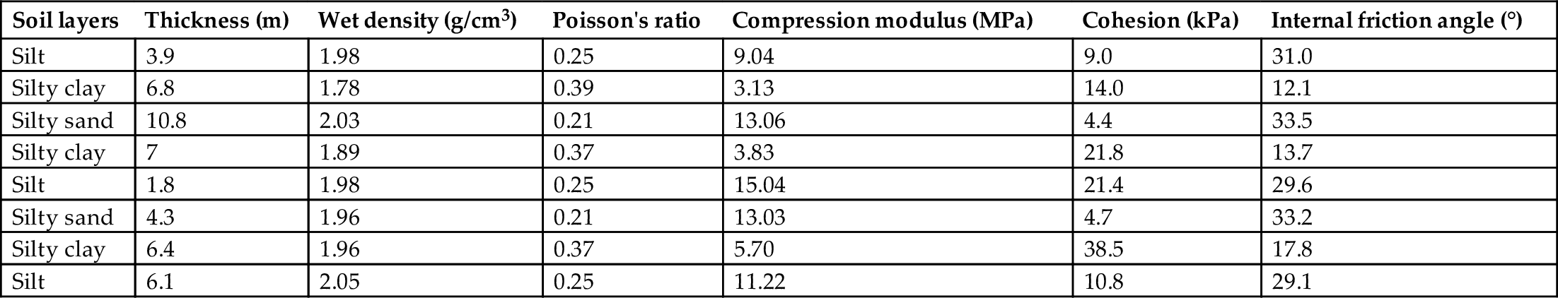
In order to investigate the bearing capacity of the CBF in a typical soil profile in China, a three-dimensional finite element model for the bearing capacity behavior of CBF is established by using the universal finite element analysis software ABAQUS, as shown in Fig. 11.6. The CBF has an outer diameter of 30 m and a clear wall height of 12 m. The finite element method (FEM) model of the foundation with the soil and the CBF are shown in Fig. 11.6A. Fig. 11.6A also shows the typical mesh with approximately 66,000 elements used in the present study. The vertical, horizontal, and rotational displacements at the bottom boundary of the soil were fully fixed, and horizontal displacements were prevented on the side boundary of the soil. Fig. 11.6C shows the seven rooms divided inside the bucket by steel plates, while the prestressed tendons are shown in Fig. 11.6D. The six peripheral rooms have the same proportions with same subdivision plate of 7.5 m long, and the middle one is a little larger. The bottom diameter of the offshore wind-powered 3-MW turbine tower is 4.4 m, and the bucket foundation top cover diameter is 30 m. A proper connection between the tower bucket and the top cover of the bucket foundation can ensure a fairly good transfer of the upper structural load to the bucket foundation. In the 3-MW turbine bucket foundation, the distance between the upper edge of the transitional segment to the soil surface is 19.8 m, and the arc portion is 16.8 m.
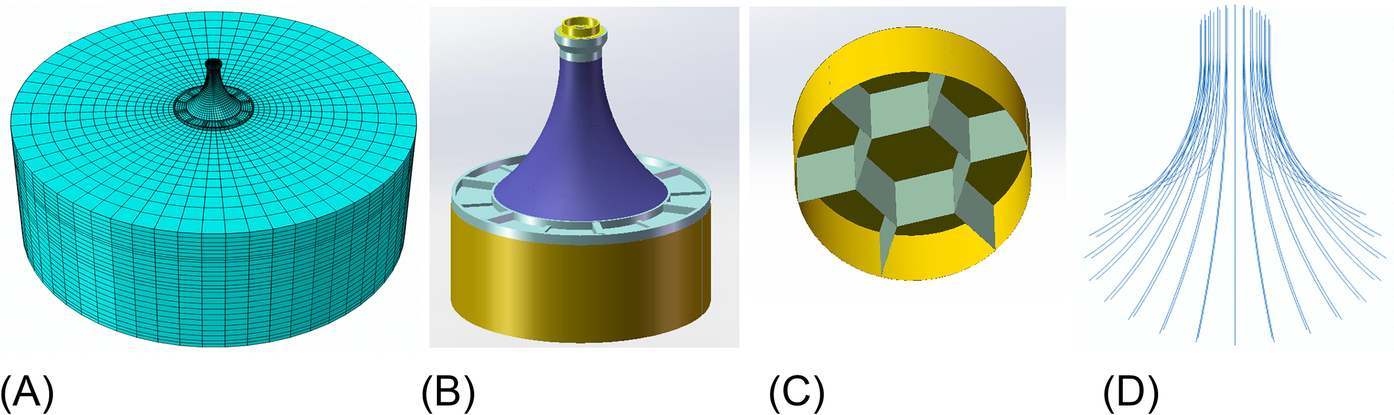
Using the parameters given in Table 11.1, soil was modeled as an elastic-plastic model based on the Mohr-Coulomb failure criterion. If the CBF is assumed to be an ideal elastoplastic model, Young's modulus is 36 GPa and Poisson's ratio is 0.2 for transmission part made of C60 concrete, while Young's modulus is 210 GPa, the yield strength is 345 MPa, and Poisson's ratio is 0.3 for steel bucket skirt and subdivision plates. For analyses, the foundation and the soils are all simulated by C3D8R elements. The contact pair algorithm in the ABAQUS is employed to simulate the contact features of the interface between the foundation and the soil. Coulomb's friction law is used to estimate the tangential ultimate frictional resistance. The foundation and the soil are stuck together and no slip happens when the shear stress on the contact surface is less than the ultimate frictional resistance. Similarly, slip occurs along the contact surface if the shear stress exceeds the ultimate frictional resistance. The contact in the normal direction of the interface is considered to be hard contact.
Table 11.1
| Soil layers | Thickness (m) | Wet density (g/cm3) | Poisson's ratio | Compression modulus (MPa) | Cohesion (kPa) | Internal friction angle (°) |
|---|---|---|---|---|---|---|
| Silt | 3.9 | 1.98 | 0.25 | 9.04 | 9.0 | 31.0 |
| Silty clay | 6.8 | 1.78 | 0.39 | 3.13 | 14.0 | 12.1 |
| Silty sand | 10.8 | 2.03 | 0.21 | 13.06 | 4.4 | 33.5 |
| Silty clay | 7 | 1.89 | 0.37 | 3.83 | 21.8 | 13.7 |
| Silt | 1.8 | 1.98 | 0.25 | 15.04 | 21.4 | 29.6 |
| Silty sand | 4.3 | 1.96 | 0.21 | 13.03 | 4.7 | 33.2 |
| Silty clay | 6.4 | 1.96 | 0.37 | 5.70 | 38.5 | 17.8 |
| Silt | 6.1 | 2.05 | 0.25 | 11.22 | 10.8 | 29.1 |
11.2.1 Force transfer mechanism of arc transitional section
The ultimate loads of 50-year return period (YRP) on the upper structure of the wind turbine that are transferred to the bottom surface of the tower bucket are the following: horizontal load of 1523 kN, bending-moment load of 109 MNm, and vertical load of 7011 kN. The load includes a safety coefficient of 1.3 and a structure importance coefficient of 1.1 (American Society of Civil Engineers, 2006), which are applied to the surface of the transitional segment of the bucket foundation. Based on the hydrological condition of the wind turbine field and considering the wave and current loads, the horizontal load increased to 2209 kN. To determine the load transfer mode from the upper structure downwards through the arc transition segment, the bending moment, shear force, and axial force data of each horizontal cross section of the transitional segment under the action of the ultimate load of 50YRP were obtained, as shown in Fig. 11.7A. The method for extraction of the cross section internal force is also shown in Fig. 11.7B.
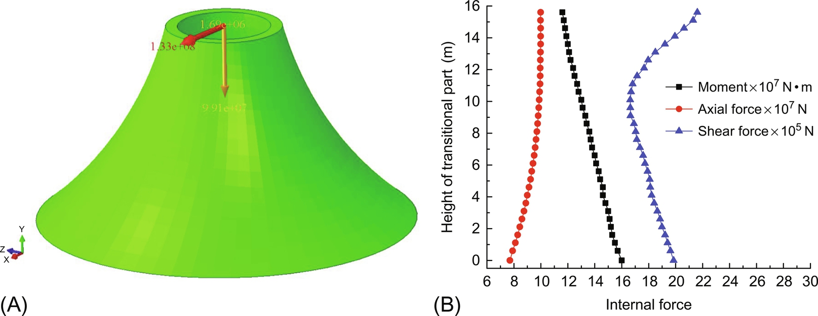
The primary characteristic of an offshore turbine combined with a bucket foundation is that the upper structure bears a tremendous bending-moment load. The bending moment of the transition segment cross section gradually increases from the top down, which includes the impact of the horizontal load. The calculated stress results of each cross section are shown in Fig. 11.8A, from which it can be seen that, under a bending-moment load, the tensile and compressive stresses at the upper portion of the transitional segment are rather high, approximately 15.3 MPa. The transitional segment cross section area gradually increases downwards, and the stress gradually reduces; at the bottom of the transitional segment, the tensile and compressive stresses on the two sides were only 0.61 MPa, which means that the large load of the bending moment at the upper structure became relatively low tensile and compressive stresses when transferred to the top surface of the bucket foundation through the transitional segment.
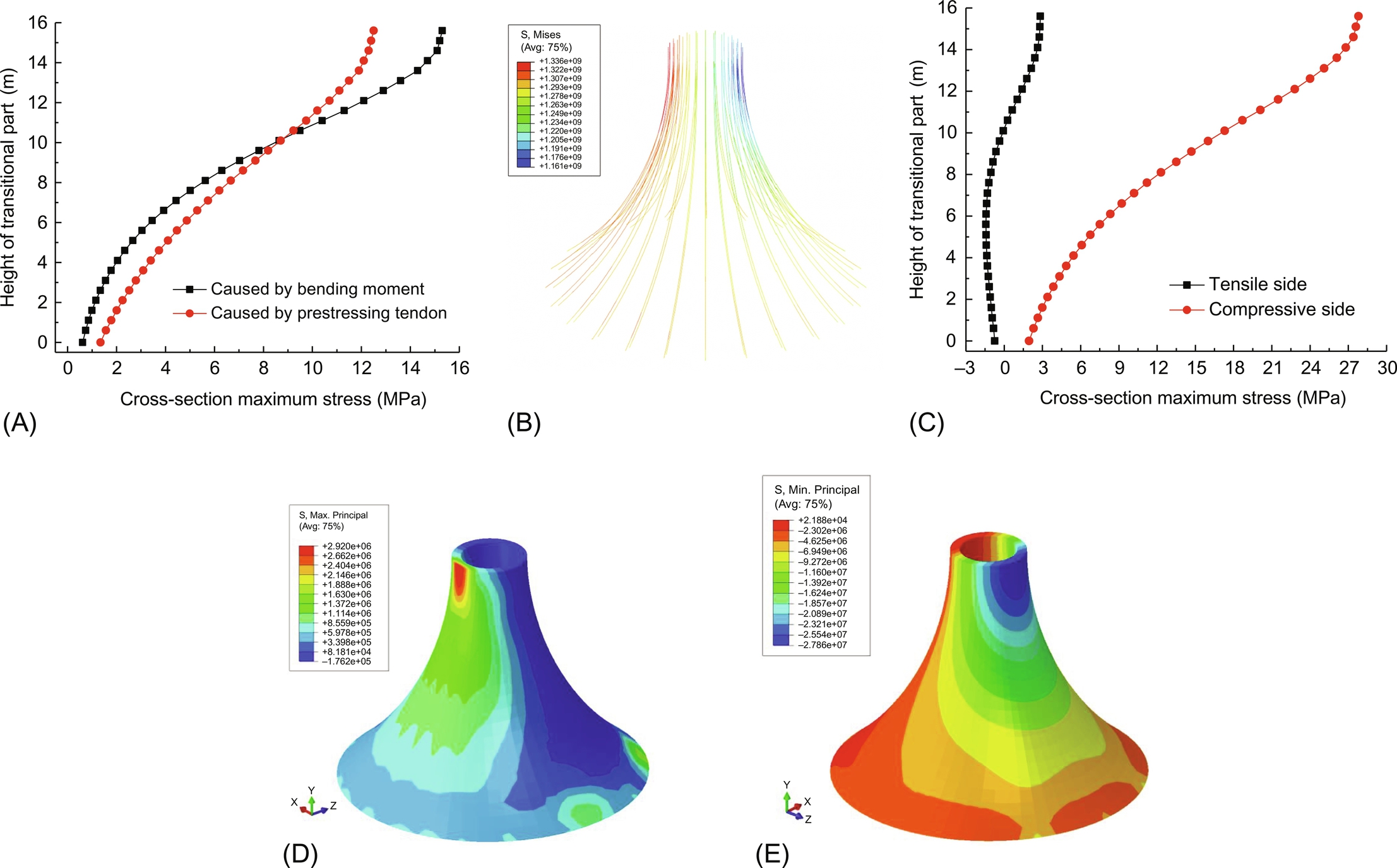
For concrete materials, the tensile stress at the upper portion of the transitional segment is too high, and the requirement is not satisfied. Thus, prestressed steel must be added. The prestressed steel is shown in Fig. 11.8B, which totals 48 bundles, and the cross sectional area of each bundle is 1530 × 10− 6 m2 with a tensile stress of 1320 MPa. The axial force of the transitional segment cross section is primarily produced by the tensile force of the prestressed steel. The maximum axial force of the transitional segment cross section is approximately 1100 MN, which is close to the combined tensile force of the prestressed steel.
The stress value of the prestressed steel under the ultimate load of 50YRP is shown in Fig. 11.8B, in which the maximum value is 1336 MPa, and the minimum value is 1161 MPa. The resultant compressive stress on the concrete is shown in Fig. 11.8C; the distribution profile along the transitional segment height exhibits a similar characteristic as the bending moment-induced cross section tensile and compressive stresses. According to the above calculations, the tensile and compressive stress of each cross section under the combined action of a bending moment and the prestressed steel are the combination of the side compressive stress of the compressed cross section along the load direction and are the tensile stress on the tensioned side of the cross section.
The calculation results are shown in Fig. 11.8C. It can be observed from the figure that the tensile and compressive stresses are greatest at the top portion of the transitional segment; the tensile stress is approximately 2.83 MPa, and the compressive stress is approximately 27.8 MPa. For C60 concrete, both of these values are between the design value and standard value, which is essentially consistent with the numerical calculation results in Fig. 11.8D and E. An appropriate amount of steel is still required in the actual project to satisfy the standard requirements. Near a height of 10 m of the transitional segment, the cross section tensile stress reduces to 0, i.e., under the ultimate load of 50YRP, there is no tensile stress in the concrete under the water surface; this is conducive to corrosion resistance in sea water. The stress value near the bottom of the transitional segment is relatively small; the compressive stress is approximately 1.96 MPa. No stress concentration appears in any cross section throughout the entire transitional segment. The huge bending-moment load at the upper structure of the turbine gradually diffuses downwards through the arc transitional segment with the prestressed steel and becomes relatively small tensile and compressive stresses. The force transfer mechanism is correct, and the structural integrity is effectively used, which means the combined bucket foundation has a high degree of safety.
11.2.2 Top cover load-bearing mode
A bucket foundation primarily includes two parts, the top cover and the bucket wall; the load-bearing mode is also generally divided into two modes, the bucket top and bucket wall load bearing. Fig. 11.9A shows the distribution characteristic of the soil pressure on the top cover and the bucket wall when the tilting degree of the bucket foundation under the bending-moment load reaches 3°. The location of the center of rotation is identified based on the finite element calculation result, which is located near and on the left side of the central axis of the bucket foundation in the opposite direction of the load. The degree of impact of the top cover, bucket wall, and bulkhead on the bucket foundation load nearing the capacity under the horizontal and vertical loads and the ultimate load of 50YRP, respectively, is shown in Table 11.2; the location of the rotation center and the soil pressure distribution under the ultimate load of 50YRP are shown in Fig. 11.9B.
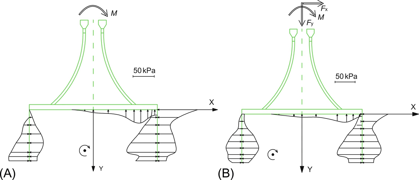
Table 11.2
| Top cover (%) | Skirt (%) | Bulkheads (%) | |
|---|---|---|---|
| Bending moment (3‰) | 57.9 | 36.3 | 5.8 |
| Horizontal load (3‰) | 50.6 | 42.1 | 7.3 |
| Vertical load (0.1 m) | 70.7 | 17.9 | 11.4 |
| Ultimate load of 50YRP | 59.4 | 29.8 | 10.8 |
It can be observed from Table 11.2 that the load-bearing ratio of the top cover under all four types of loads exceeds 50%, which in the case of the ultimate load of 50YRP is closest to reality; in this situation, the top cover bears approximately 60% and the bucket wall and bulkhead bear approximately 30% and 10% of the load, respectively. The configuration of the bulkheads is primarily for the convenience of towing and submerging and can only provide a small safety margin under loading; therefore, it can be determined that the load-bearing mode of the offshore wind turbine combined with a bucket foundation is a “cover-load-bearing type”, such that the top cover bears most of the load and is supplemented with bucket wall load bearing.
11.3 Model tests on the bearing capacity of composite bucket foundation
The CBF evaluation was carried out in a large artificially excavated test pool located along the coast of Jiangsu. The soil was placed in the tank by an excavator layer by layer, to a total depth of 3 m. The top soil requires elaborate preparation to make it flat. The soil around the pool is mainly fine sand. The saturated density of the soil is 1806 kg/m3 and the water content is 33.5%. Its liquidity index and plasticity index are 1.19 and 11.75, respectively. The compressive modulus Es of the soil is taken as 3.69 MPa for a proper ultimate state, and its cohesion strength c and internal friction angle φ are 3.84 kPa and 7.14 degrees, respectively.
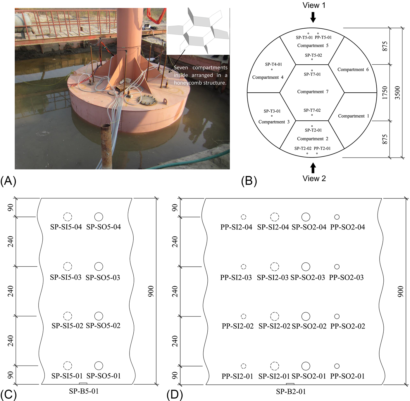
The bucket foundation in the tests has an outer diameter of 3.5 m and a clear wall height of 0.9 m. The seven rooms are divided inside the bucket by bulkheads as shown in Fig. 11.10. The six peripheral rooms have the same proportions, and the middle one is a little larger. A steel tube is connected to the lid and reinforced by six ribbed plates as part of this CBF, and the tube is also used for horizontal loading as part of a wind turbine tower. Lifting lugs are required and attached to the tube for applying horizontal load at the height of 2 m, 3 m, 4 m, and 5 m, as shown in Fig. 11.10A. Meanwhile, in order to have a clearer knowledge on the ultimate bearing capacity of the CBF in saturated muddy clay, a three-dimensional finite element model for the bearing capacity behavior of CBF is established by using the universal finite element analysis software ABAQUS, as shown in Fig. 11.10B and C.
11.3.1 The deformation mechanism and the soil-structure interactions of CBF under horizontal load
Fig. 11.11 shows the load-displacement relationship of the CBF under different loading heights. The curves contain both inflection and extreme points. The inflection points indicated that the plastic failure of the soil took place outside the wall under the action of the corresponding load, but the soil pressure on the lower surface of the lid at the passive zone still had a growth trend for the horizontal restraint of the bulkheads. The horizontal tension loading at the extreme points is taken as the ultimate bearing capacity of the CBF. Under such a condition, the failure mode of the foundation can be determined according to the distribution of the equivalent plastic strain in the soil.
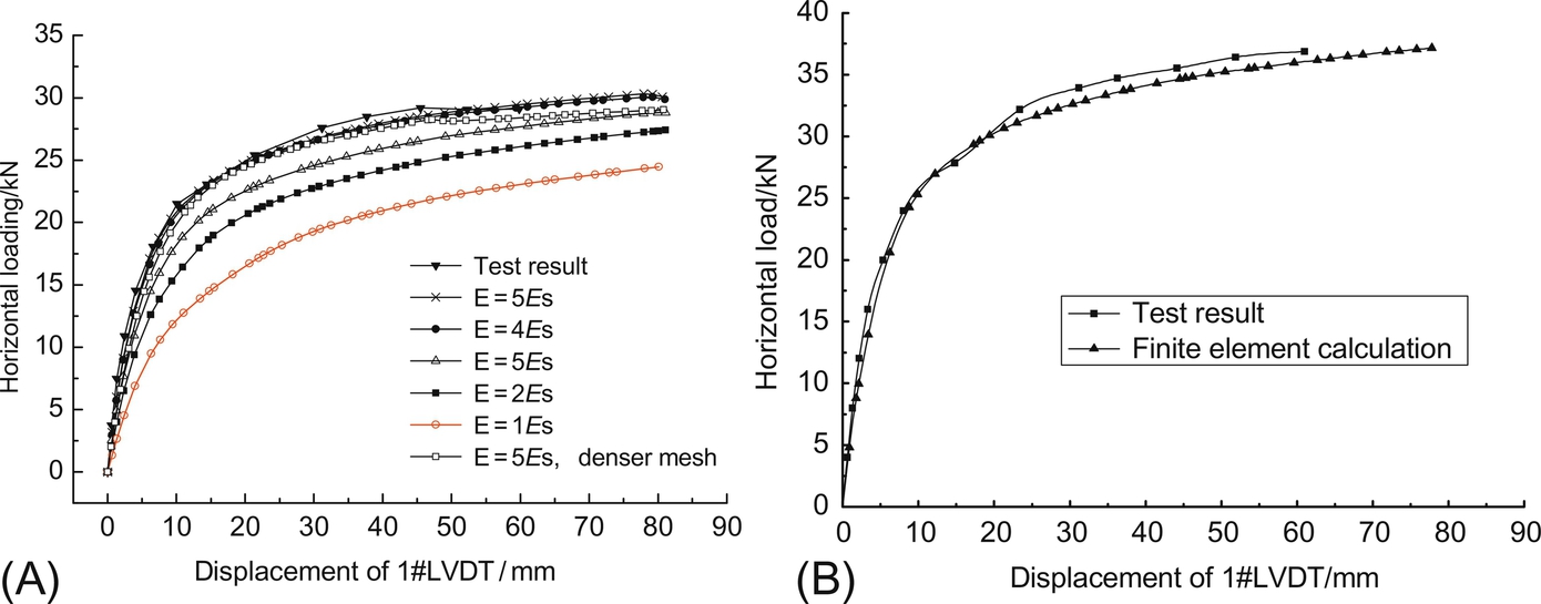
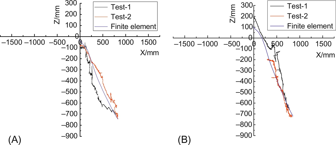
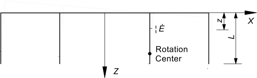
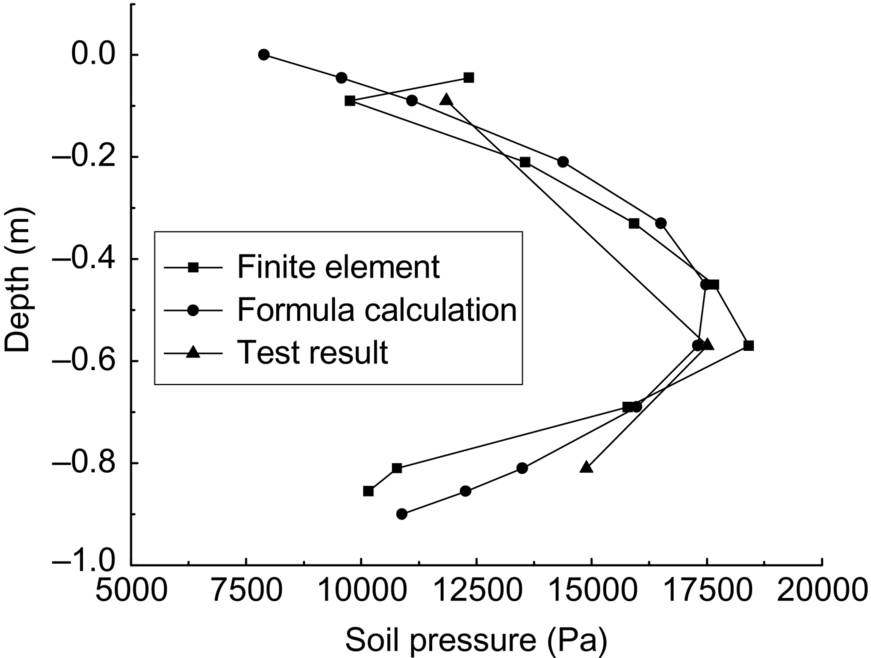
According to the test results and finite element analysis, the calculated positions of instantaneous rotation centers of the CBF are shown in Fig. 11.12. The horizontal load tests at the heights of 3 m and 4 m were conducted twice each. The position of the instantaneous rotation centers moves from the lid center to the bottom of the bulkhead at the loading direction with the increase of horizontal load. The rotation center is approximately 0.8 L below the ground surface around the bulkhead at the loading direction under ultimate horizontal load, (where L is the depth of the bucket). Its position and the schematic diagram of the CBF rotation are shown in Fig. 11.13; the coordinate of the rotation center is assumed to be X0 =  , Z0 = 0.8 L. The soil pressure on the outer wall in the loading direction is shown in Fig. 11.14, along with the test results, the finite element calculation results, and the formulas, all of which are in basic agreement.
11.3.2 Failure envelope
In offshore wind turbine engineering, the foundations are usually subjected to a huge horizontal load and a huge bending moment for the high tower tube. The composite bearing capacity of the CBF will be clearer for establishing the failure envelope on the basis of these experiments. In order to obtain the failure envelope of the foundation under combined loading, load-controlled analysis and displacement-controlled analysis have been used in numerical simulation. The results show that the yield surfaces determined by the load-controlled and displacement-controlled approaches are consistent.
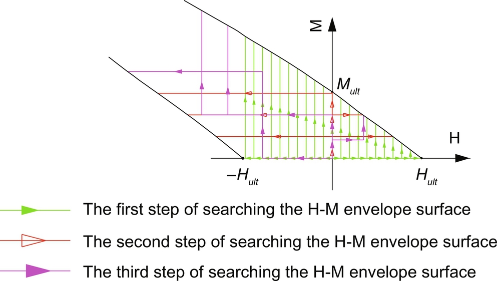
The failure envelope of the foundation was obtained using the load-displacement control search method, which basically consists of the following steps. 1) A specific horizontal load (Hi, a proportion of Hult) is applied based on the ultimate horizontal bearing capacity Hult and ultimate moment bearing capacity Mult. The load Hi remains unchanged when a radian displacement is applied until the corresponding moment load no longer increases. The failure envelope is obtained as shown in Fig. 11.15. 2) A specific moment load (Mi, a proportion of Mult) is applied based on the ultimate moment bearing capacity Mult. The load Mi remains unchanged when a horizontal displacement is applied until the corresponding horizontal load no longer increases. 3) A lower horizontal load Hi or moment load Mi is applied to the top surface of the CBF, increasing alternately within the failure envelope, and a horizontal displacement or radian displacement is applied at the end of each search. The search method of the three steps is shown in Fig. 11.15, and the failure envelope of H-M is finally shown in Fig. 11.16.
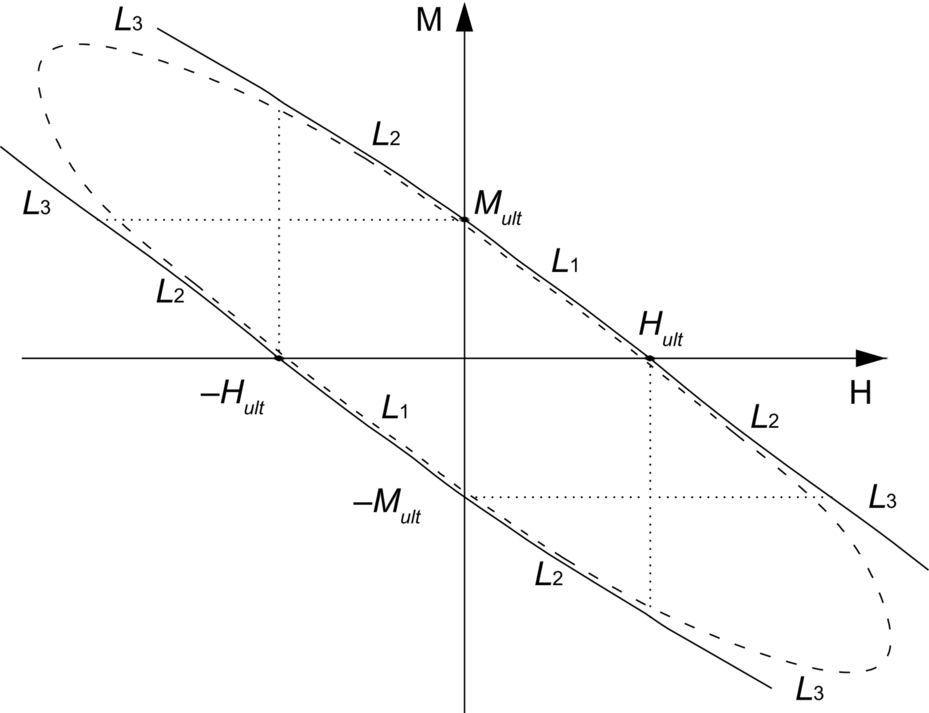
As a qualitative research in Fig. 11.16, there are two possible shapes of the failure envelope based on different extreme methods. For the solid lines in Fig. 11.16, as mentioned in Section 11.4.1, the loading at the extreme points is taken as the ultimate bearing capacity. The solid envelope curves are close to linear in limited spaces and have a larger envelope scope. For the dashed lines, the ultimate bearing capacity is determined by using the tangent intersection method, which is a little conservative. The failure envelope of CBF can be divided into three sections: L1, L2, and L3, where L1 comes into being when H and M are in the same direction and it is independent with the search path, L2 comes into being when H and M are in the opposite direction and one of them is in the scope of uniaxial ultimate value, L3 comes into being when H and M are in the opposite direction and none of them are in the scope of uniaxial ultimate value, and L2 and L3 require a proper search method. From the results, we can see that the horizontal load and moment have influences that counteract the CBF when they are in opposite directions. At this time, the composite ultimate bearing capacity may exceed the uniaxial ultimate bearing capacity of Hult or Mult.
11.4 Model tests on the installation of composite bucket foundation
To obtain the pressure inside the compartment, soil pressure, and water pore pressure, pressure transmitters, soil pressure cells, and pore water piezometers were fixed on the CBF (see Fig. 11.17). There are 26 soil pressure sensors with a diameter of 0.02 m embedded in the steel plate, with eight in the top cover (see Fig. 11.17A), two at the skirt tip, along the skirt eight toward inside and the remaining eight toward outside (see Fig. 11.17B–D). Meanwhile, there are eight water pore pressure sensors embedded in the skirt wall of the caisson, with four toward inside and the remaining four toward outside, while there are another two sensors fixed on the top cover of the CBF. In addition, there are seven pressure transmitters on the top lid of the bucket for every compartment. The main equipment used in model tests includes the gas/water pump system and tube system and data collection system. The layout scheme and picture of the experimental equipment on test site are illustrated in Fig. 11.18.

In order to investigate the feasibility of tilt adjusting technique, two installation tests were carried out for two different sinking methods. For Test 1, the sinking process proceeded without interruptions under negative pressure. The process took approximately 20 min from the time when sinking under self-weight began to when the top cover contacted the mud surface. The negative-pressure tubes of seven compartments of the CBF converged to a common tube that was connected to the negative-pressure pump. During the sinking process under negative-pressure, the valves of the negative tubes of all the compartments were controlled to level the foundation in a timely operation. When the foundation started to tilt, the valves of the lower compartments were switched to reduce the suction gradually until they were closed; however, the upper compartments were allowed to continue to sink. After the required levelness of the foundation was achieved, all of the valves were opened so that the entire foundation could sink. This process was repeated until the bucket foundation was completely sunk.
By comparison, in Test 2, a negative pressure was produced in the top compartments to level the foundation (the maximum height difference between the two ends was within 1 cm) and, each time the bucket foundation sank 10–15 cm, the negative-pressure production stopped. The inclination of the bucket foundation was calculated using a gradienter, an inclinometer, and a ruler to directly measure the distance between the head cover surface and the water surface. A negative pressure was produced in all of the compartments to allow the bucket foundation to gradually sink into the clay until the head cover contacted the mud surface.
11.4.1 Test 1
Fig. 11.19 shows the variations in the air pressure in each compartment during the sinking process under self-weight and the sinking process under the negative pressure of the CBF. In the initial stage of sinking under negative pressure, the negative pressure of each compartment of the bucket foundation increased linearly to approximately − 0.01 MPa. As the bucket foundation continued to sink, the mean extreme value of the negative pressure of each compartment was approximately − 0.02 MPa. Even though the overall vertical sinking of the bucket foundation was achieved by controlling the valve of each compartment, the negative-pressure value of each compartment could not be accurately controlled under the actual conditions. The valves of some compartments were not opened sufficiently rapidly after they were closed, resulting in a positive pressure in these compartments for a short period of time. The sinking speed of the CBF and the minimum negative pressure necessary for sinking could not be effectively controlled. The problems that arose during this sinking experiment were systematically solved in the subsequent CBF sinking experiments. An improved scheme was also developed for use as a reference for sinking wind turbine foundations in practical applications.

Fig. 11.20 illustrates the variations in the pore pressure in compartment 2 during the penetration process. A top cover pore pressure sensor was used to verify the pressure sensor measurements. The values measured by the two types of sensors were essentially the same. The negative-pressure values measured in compartment 2 were used to plot the variation in the sidewall pore water pressure, showing that the pore water seepage from the negative pressure in the bucket produced an excess pore water pressure on the internal and the external walls of the bucket. The excess pore water pressure at the top of the internal wall was close to the negative pressure and gradually decreased. The excess pore water pressure at the bottom of the external wall was close to the negative pressure inside the bucket and gradually rose to zero at the top of the external wall.
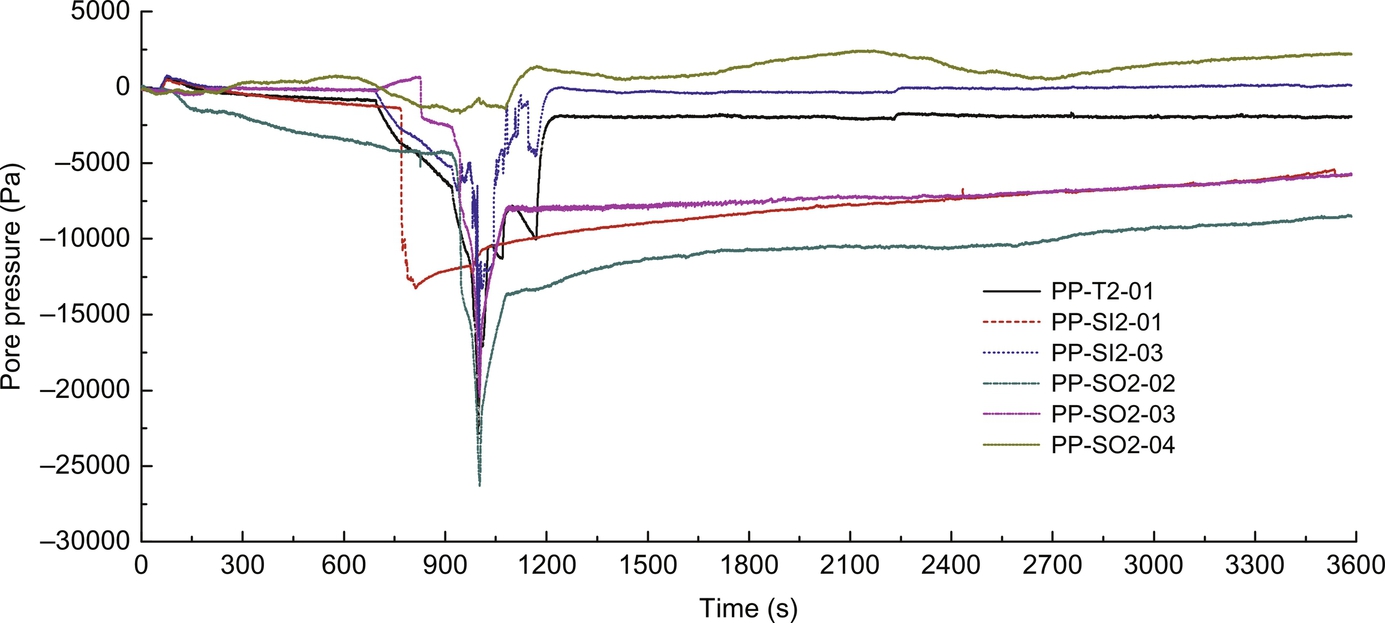
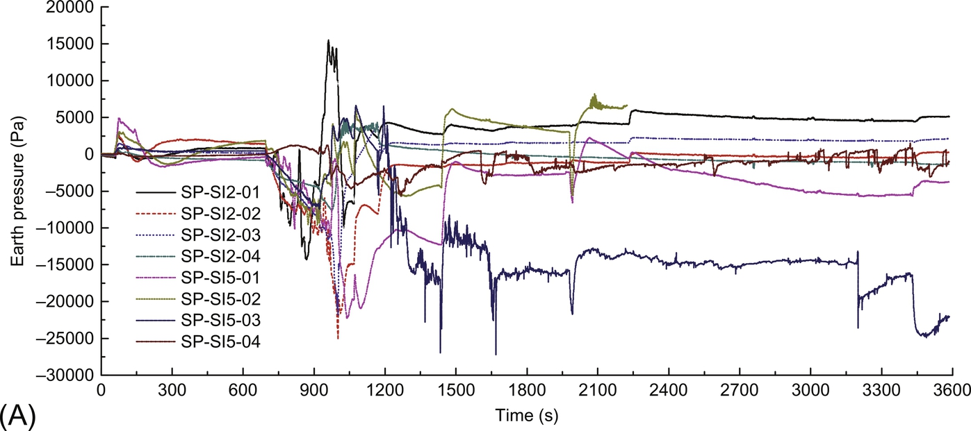
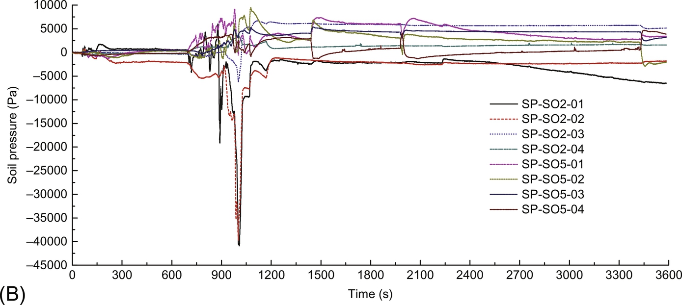
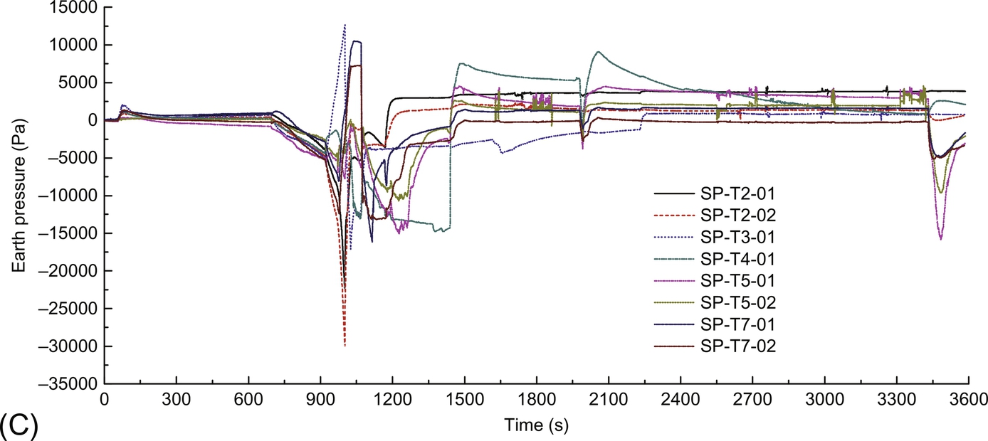
Fig. 11.21 shows the variations in the earth pressure during the sinking process of the CBF. The earth pressure of the internal (see Fig. 11.21A) and the external walls (see Fig. 11.21B) of the bucket and the head cover (see Fig. 11.21C) was significantly affected by the negative pressure. When the negative pressure was being produced, the earth pressure of the head cover that was measured by the sensor was essentially the same as the negative-pressure value produced in each compartment. The earth pressure at the internal side of each compartment was negative, all of the earth pressures at the external side of compartment 2 were negative, the negative pressure at the bottom was relatively larger than the other pressures, and the negative-pressure value at the top was relatively smaller than the other pressures, which was in agreement with the distribution of the excess pore water pressure.
11.4.2 Test 2
The sinking process under a negative pressure lasted for a relatively long time in this experiment. In the initial leveling stage, the bucket foundation sank under self-weight for the first 30 cm. A negative pressure was then produced in all of the compartments, and the bucket foundation sank to a further depth of 10 cm. After the foundation was leveled, a power outage occurred. The sinking under negative pressure continued the next day. Real-time monitoring was not conducted for the first 40 cm of sinking because of instabilities in the voltage.
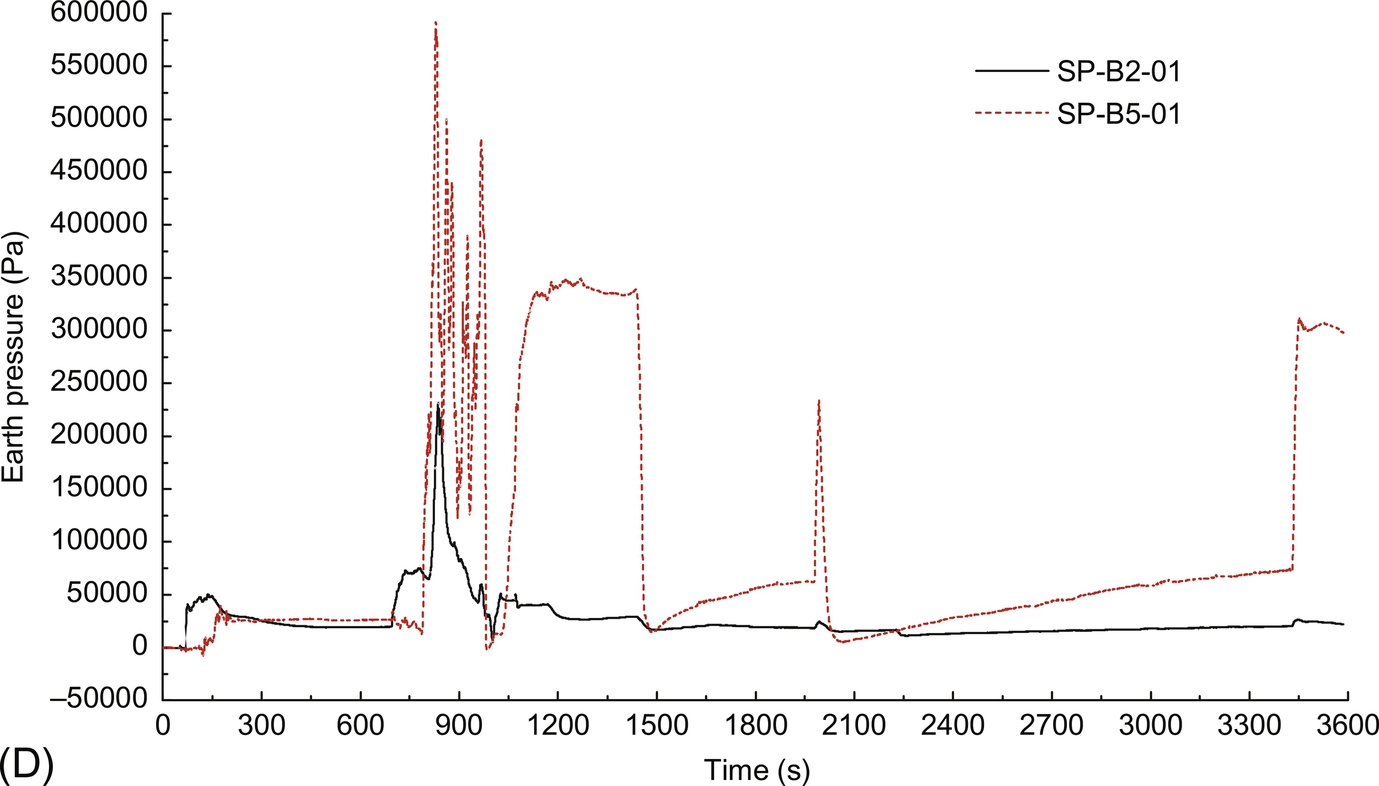
Fig. 11.22 shows the pressure variations in all of the compartments during the last 50 cm of sinking the bucket foundation. A very short time was needed for the bucket foundation to sink 10–15 cm each time. The extreme negative pressure in each compartment was in the − 0.01 MPa range during the sinking of the CBF and each compartment exhibited a different extreme negative pressure.
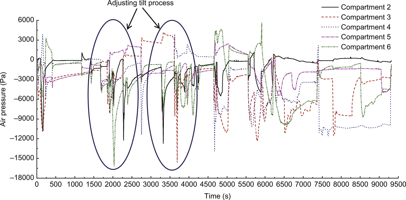
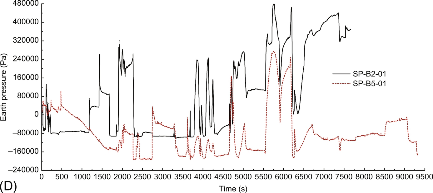
Fig. 11.23 illustrates the variations in the pore pressure in compartment 2 in Test 2. Fig. 11.24 shows the variations in the earth pressure during the sinking process of the CBF. The earth pressure of the internal (see Fig. 11.24A) and the external walls (see Fig. 11.24B) of the bucket and the head lid (see Fig. 11.24C) was significantly affected by the negative pressure, while the Fig. 11.24D shows the variations of the earth pressure at the bottom of the wall of the bucket. The adjusting tilt processes were indicated by the change of pore pressures and earth pressures along the skirt wall. The foundation was leveled by producing a negative pressure in the top compartments, pumping air into the bottom compartments or using both of the aforementioned methods. After the foundation had stabilized for 20–30 min, the inclination was measured again. If the required inclination (i.e., that the maximum height difference between the two ends should be within 1 cm, a levelness of 0.29%) was not obtained, then the foundation was leveled further. If the requirement was met, then a negative pressure was produced to allow the foundation to sink 10–15 cm. This process of sinking-adjusting-stabilizing-sinking was repeated until the head cover contacted the mud surface. A negative pressure was continuously produced in the top compartments to level the foundation. The production of negative pressure continued for several hours to strengthen the soil mass inside the bucket. The maximum height difference between the two ends was maintained to within 1 cm for the final leveling of the bucket foundation.


11.4.3 Comparisons
For Test 1, during the sinking process under negative pressure, the pore water seepage resulted in the vanishing of the resistance on the sidewall. To balance the gravity of the bucket foundation with the force generated at a certain sinking speed, the end resistance at the bottom of the bucket displayed an increasing trend during the sinking process under negative pressure. After the sinking process under self-weight had stabilized, the earth pressures at the bottom were 0.019 MPa and 0.026 MPa. During the sinking process under self-weight, the bucket foundation tilted to a certain extent, resulting in an uneven distribution of the earth pressure at the bottom. As the sinking depth increased, the maximum earth pressure at the bottom of compartment 2 reached 0.22 MPa, whereas the mean maximum value of compartment 5 was approximately 0.35 MPa.
From the results of Test 1, it was found out that there was a main tilt adjusting process started at about 1000 s in the Test 1. The compartment 3 was lowest among the compartments. Firstly, the positive pressure in compartment 3 was increased to reduce the levelness while increasing the negative pressure of compartment 1, 5, and 6. Then, it was a backup plan operated by increasing the positive pressure in the middle larger room 7 to lift up the whole foundation. Consequently, the penetration process could be restarted by applying different negative pressure for all compartments until the CBF was installed into the designed depth.
In Test 2, there were two main tilt adjusting process. From 500 s to 2000 s, the negative pressures in different compartments were almost the same until the obvious tilt adjusting process appeared around the 2000 s. The pressures in compartment 1 and 6 were negatively increased to reduce the levelness of the CBF, while those in compartment 3 and 4 were positively increased. The next tilt adjusting process happened around the 3500 s by increasing negative pressures of compartment 2 and 3 with adding the positive pressure of compartment 5 and 6. Meanwhile, the corresponding values of pore and earth pressures illustrated the occurrence of tilt and adjusting processes, which show that the compartment 1 and 6 were higher than compartment 3 and 4 around 2000 s and the compartment 2 and 3 were higher than compartment 1 and 6 around 3500 s. The tilt of the CBF to a certain extent would result in an uneven distribution of the earth pressure at the bottom. When the levelness of the CBF was limited, the pressure values obtained from the skirt tip of compartment 2 and 5 were almost the same, for example, from 2500 s to 3500 s.
11.5 Conclusions
The composite bucket foundation (CBF) is a new type of foundation for offshore wind turbines, which can be adapted to the loading characteristics and development needs of offshore wind farms due its special structural form. There are seven rooms divided inside the CBF by steel bulkheads, which are arranged in a honeycomb structure. The six peripheral rooms with the skirt have the same proportions, while the middle orthohexagonal one is a little larger. With the seven-room structure, the CBF has reasonable motion characteristics and towing reliability during the wet-tow construction process. Through extensive research into the force transfer characteristics and stress mechanisms of composite structure systems, a CBF structure system with definite force transfer and stress systems has been developed. The large bending moment and horizontal force of the wind turbine tower are transferred to and dispersed into the sea floor soil through a prestressed curved concrete transition section, the head cover of the bucket foundation, the sidewalls of the bucket foundations, and the internal steel compartment plates. The deformation mechanism, the soil-structure interaction, and the ultimate bearing capacity of the CBF are determined depending on the tests. Based on the position of the rotation center, soil pressure and ultimate bearing capacity for the CBF are presented. Moreover, by means of numerical simulation, the envelope curve of ultimate bearing capacity of the CBF is described in H-M load space, clarifying the load-bearing characteristics of the CBF under combined loads.
The penetration depth and levelness determine the required bearing capacity and stability of the CBF for the expensive wind turbines. Specially, the tilt installation tolerance is very limited for offshore wind foundations, which has critical impacts and an insignificant reduction in turbine working behaviors. The installation model tests on a CBF with seven compartments were performed in order to investigate the feasibility of a foundation tilt adjusting technique by applying suction/positive pressure and intermittent pumping among the rooms. The tests represent the tilt adjusting techniques of the CBF. Two sinking strategies were taken in the tests that are the continuous sinking by applying different suction in different compartments without any interruption and the sinking process of sinking-adjusting-stabilizing-sinking by applying negative/positive pressure among the divided rooms of CBF. The results show that increasing the negative pressure in lower side compartment and the positive pressure in higher side compartment can effectively reduce the levelness of the CBF. Meanwhile, lifting the foundation by pumping the positive pressure in the middle larger compartment and applying the different negative pressure in all compartments again are another alternative method when the adjusting tilt process meets difficulties. The on-site tests data are effective for further study on the design and construction of CBF with seven compartments.