"Light is but the shadow of God." - Sir Thomas Browne
The first time you ever see your lighting work on a video display, it's an eye-opening experience. That which you thought was so well-lit, evenly illuminated, sufficiently modeled and well defined might turn out to be very different than your eyes lead you to believe.
Video renders lighted objects very differently than the human eye because of the differences in the way visual information is sensed, processed, and displayed. It differs vastly from that of the human visual response. Not only do colors appear very differently displayed on a video monitor than they do in real life, but the video camera is also much more sensitive to variations in light levels. The human eye is a truly remarkable instrument that automatically compensates for vast differences in lighting levels. But the video system doesn't have the same ability. Therefore, a video engineer has to monitor the display and adjust the iris of the camera in order to compensate for these variations. But most video engineers would rather not have to rely on constant monitoring and adjustment to produce good work.
One of the biggest challenges facing the lighting designer of a house of worship is creating a video wash with as much uniformity across the entire platform as possible. But it's not as straightforward as it might seem. If we could use a single instrument to illuminate the entire platform then it would be an easy task - just flatten the field and wash the stage with a nicely uniform white light for the video camera.
Unfortunately, it's usually much more complex than that. We typically use multiple light sources in order to control light spill and to isolate certain areas of the platform such as the podium or a soloist in the choir. Even if these weren't issues that we had to deal with, a single source that was powerful enough to illuminate even a medium-sized platform would be very large and unwieldy. For these reasons, we most often choose to use multiple luminaires and blend them as well as we possibly can to create a smooth and uniform video wash.
Most people trained in video production are used to using Fresnels or PAR cans for key light when they want a video wash. But they most often produce video in a studio with a cyc in a very controlled environment. They aren't used to dealing with a live audience, a central subject, a mid-ground, and a choir or other subjects in the background. Many of the lighting techniques used in video production are vastly different than those used in lighting for houses of worship. We use particular instruments for particular reasons and with the right considerations, we can get good results.
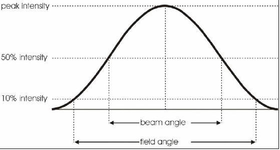
Most modern ellipsoidal reflector spotlights (ERS) can be adjusted manually to create a peaked beam or a flat beam. When they are adjusted with a peaked beam, we say that they are optimized for a “cosine distribution” or a “blending distribution.” That simply means that the beam profile follows the shape of a cosine. In the ideal profile distribution, the center of the beam peaks at the maximum intensity and it falls off towards the edges as shown in the illustration below.

Figure - A beam profile showing the center beam peak, the beam angle, and the field angle.
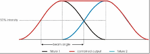
The reason a blending distribution profile is ideal is because when you overlap two fixtures at the 50% drop-off, they produce a uniform field between them, as shown by the illustration below.

Figure - Two fixtures with a cosine distribution overlapping at the 50% drop-off produce a uniform distribution of light.
Notice in the illustration that the two fixtures overlap at point at which the intensity drops to 50% in the beam profile. That is the beam angle (as opposed to the field angle, which is the 10% drop off).
If we then align several fixtures and focus them side-by-side so that they overlap at the beam angle, we can see that the area under the curve above is perfectly uniform in intensity (excluding the two ends). This illustrates that the beam angle is a useful tool to help calculate the width of a uniform wash when we blend a number of fixtures. We can conclude that, when we blend a number of fixtures, the width of the uniform wash is the diameter of the beam at a given throw distance multiplied by the number of fixtures minus one.
Width of wash = (number of fixtures – 1) x diameter of beam

Figure - Several fixtures overlapping at their respective beam angles producing a uniform wash.
The graphic above illustrates this formula. There are five fixtures, and the uniform wash is four times the width of the beam of a single instrument. The width of the wash and the diameter of the beam should be in the same units. For example, if we calculate the width of the beam diameter in meters, then the width of the wash will also be in meters. If we use inches instead, then the width will be in inches. This formula provides us with a handy tool to quickly evaluate how many instruments are needed to light a particular area.
The uniformity created by blending two fixtures with an ideal blending distribution works well when the two fixtures are projected straight onto the subject. But when they are projected at a 45 degree angle, as they are in the McCandless method, then the model breaks down. The 45 degree angle of projection introduces some fall off of the intensity on the far edge of the beam. The fall off follows the inverse square law, which says that the intensity of light falls off exponentially as the throw distance increases linearly.
Illuminance = luminous intensity ÷ (throw distance)²
For example, suppose our throw distance is 15 feet and the illuminance is 614.5 footcandles, as shown below. If we double the throw distance to 30 feet, then the illuminance would not drop in half, but it would drop by a factor of four to 153.6 footcandles. So we can see that any change in the throw distance results in an exponential change in the illuminance.

Figure - Doubling the throw distance results in a four-fold decrease in illuminance.
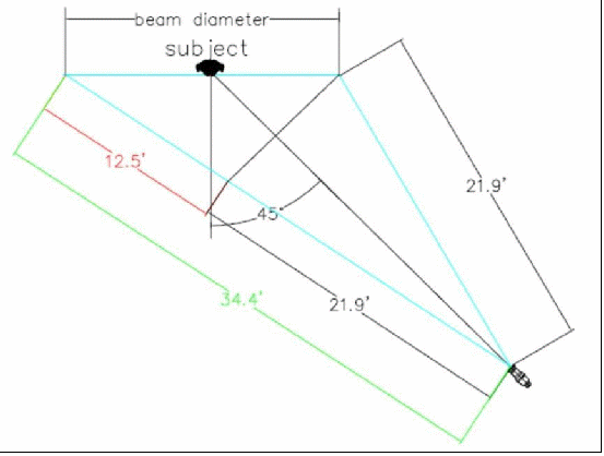
When we skew the angle, the throw distance varies from the side to the far side and the illuminance changes across the beam.

Figure - When lighting a subject at an angle, the near side of the beam is much closer than the far side of the beam.
The illustration above shows what happens to the illuminance across the front of the subject when we project the light at a 45 degree angle. In this example the throw distance on the near side of the beam is 21.9 feet but at the far side of the beam the throw distance is 34.4 feet. That means that the throw distance on the far side of the beam is 12.5 feet longer, or 57% farther, than that of the near side of the beam. In terms of illuminance, we can use the throw distances to calculate the relative difference from the near side to the far side. If we assume the illuminance on the near side is unity (1 unit), then the luminous intensity is 479.6 lumens. The illuminance at the far side of the beam would then be 0.405. That's two and a half times less than the near side.
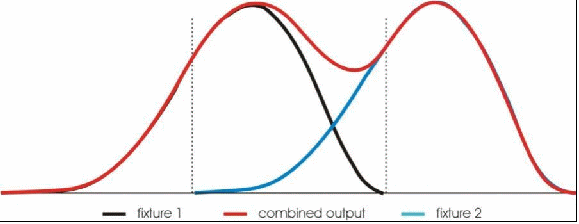
The illustration below shows the blending distribution for two fixtures when they are projected at a 45 degree angle. As we can see, the perfect uniformity that we saw in the previous example is lost. Instead, there is a cold spot between fixtures due to the fall-off of the intensity from the near side of the beam to the far. When even more fixtures are blended in this manner, it produces a series of hot spots and cold spots instead of the uniform video wash we saw in the previous example.

Figure - The blending distribution of two overlapping beams being projected at a 45 degree angle.
To avoid this problem we need to reassess how we set up our key light or video wash and how we design our lighting system. Instead of using a key light and a fill light at 45 degree angles to the subject, we can move the key light so that it projects directly on the subject and relocate the fill light. The logical place to move the fill light is on either side of the subject. This is not the classic McCandless three-point lighting system but a variation of it.
For applications without video, the non-uniformity of the wash created by blending a row of fixtures projected at a 45 degree angle is not critical. It is usually acceptable because the human eye is forgiving and it doesn’t see the hot and cold spots as well as a camera does. But in the event that video is involved, this set up can pose problems. For that reason, the 4-point lighting system, where the key light is focused straight on to the subject and two fill lights are located on either side of the subject might a better solution for creating a video wash. We will discuss more about the four-point lighting system and how to design a complete lighting plot with it in the next chapter.
Concepts:
A cosine or blending distribution is a beam profile with the shape of a cosine curve. An ideal blending distribution provides perfect uniformity when blended two or more luminaires are blended.
When you blend a number of fixtures with a cosine distribution, the total width of the resulting wash is equal to the number of fixtures minus one, times the diameter of the beam at the given throw distance.
The inverse square law says that the intensity of light falls off exponentially as the throw distance increases linearly.
Blending fixtures with a cosine distribution projected at an angle does not produce a uniform wash.
Formulas:
Width of wash (feet) = [number of fixtures -1] x diameter of beam (feet)
Illuminance (footcandles) = luminous intensity (candelas) ÷ [throw distance (feet)]²
Illuminance (lux) = luminous intensity (candelas) ÷ [throw distance (meters)]²
Words to know:
cosine distribution - a beam profile that follows a cosine function. Also known as a blending distribution
blending distribution - a beam profile that produces a uniform area of coverage when blended with a like fixture
inverse square law - a law defining the relationship between the illuminance (lux or footcandles), the luminous intensity (candelas) and the throw distance; the illuminance is equal to the luminous intensity divided by the square of the throw distance