"Think of yourself as an incandescent power, illuminated and perhaps forever talked to by God and his messengers." - Brenda Ueland
Now that we understand the main elements of a lighting system, we can consider how to select its components. Before we discuss the selection of lighting fixtures for specific applications, let’s consider all the lighting tools available to us.
The types of luminaires from which we will choose for key light, fill light, and back light include PAR cans, ellipsoidal reflector spotlights (ERS), and Fresnels. Automated lights are a special case and are typically either spot fixtures, similar to an ERS, or wash fixtures, similar to a Fresnel fixture. Each of these fixtures has advantages and disadvantages. We'll consider each type and discuss their attributes.

The parabolic aluminized reflector fixture, or PAR can, is available in a variety of sizes including PAR 16, PAR 36, PAR 46, PAR 56, and PAR 64. The number is a measure of the diameter of the fixture in eighths of an inch, so a PAR 64, for example, is eight inches in diameter. The lamps that fit in a PAR can, with the exception of a PAR 16, are sealed-beam incandescent lamps, much like the old style sealed-beam car headlight, with an integral reflector. They are available in a variety of wattages and lumen output, including long-life versions that last about 2000 hours. PAR lenses that fit on the front of PAR cans are available with a variety of field angles including: very narrow spot (VNSP); narrow spot (NSP); medium flood (MFL); and wide flood (WFL). Most PAR 64s can be purchased with a set of interchangeable lenses.
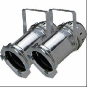
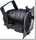

Figure 29 – L-R: two PAR 64s; snub-nose PAR 56; PAR lamp.
PAR cans are relatively inexpensive and output a relatively large amount of light. Because there are no optics other than a reflector and the output lens, the optical efficiency of the luminaire is very high; they lose little light to optical components. The down side is that incandescent lamps have very poor efficiency and they have poor uniformity. They also image the filament enough to produce slight aberrations in the field and they have no integral means of controlling light spill. Barn doors can be purchased for that purpose as an accessory.
The ellipsoidal reflector spotlight is sometimes referred to by the generic name “Leko.” The name is derived from the Century Lighting trade name Lekolite, which was named after its inventors, Joseph Levy and Edward Kook. ETC was the first to introduce an ERS with a compact filament lamp source, which is very efficient compared to the original Lekolite. A 575-watt Source Four ERS produces about the same amount of light as a 1000-watt Lekolite. That not only saves energy, it also produces less heat that needs to be removed by the HVAC (heating/ventilating/air conditioning) system. Other theatrical stage lighting manufacturers have followed suit with their own version of an ERS with a compact filament lamp source including Altman Shakespeare, Colortran Leo, Strand SL Coolbeam, Selecon Pacific, and others.
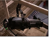
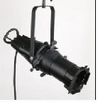
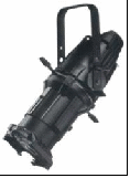
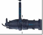
Figure 30 – L-R: Altman Shakespeare; Colortran Leo; ETC Source Four; Strand SL Coolbeam.
ERS fixtures in North America are typically used with interchangeable fixed lenses as opposed to zoom lenses, which are more common in Europe. They can be used for short throw applications with a wide lens or long throw applications with a narrow lens. The lamps are typically 575-watt or 750-watt compact arc quartz halogen lamps but ERS fixtures are also available with discharge lamps. In the rear of the fixture is a manually adjustable setting to center the lamp and create a peaked beam or a more uniform flat beam. They also have built-in shutters which allow you to control light spill and frame objects and set pieces. On the negative side, ERS fixtures are higher in cost than a PAR can or a Fresnel fixture.
A Fresnel fixture has a lens, called a Fresnel lens, with a series of stepped, concentric rings that produces a soft, unfocused light. The fixtures range in size from three inches to 24 inches with lamps that range from 150 watts to several thousand watts.
Fresnel fixtures are ideal for providing very soft, unfocused light, and they are relatively inexpensive. They are commonly used in television and film production. But they are extremely inefficient and it can be challenging to use them with anything but a relatively short throw. They are often used with barn doors to control light spill but they are not recommended for throw distances of more than 20 or 30 feet except under very controlled circumstances. They are also such large fixtures that they can easily block the line of sight of the audience and therefore they are not often used for key light except in a studio with no live audience or where the audience is secondary to the cameras.
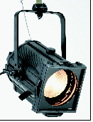
Figure 31 - Philips Selecon Rama 150 Fresnel.
Because of their flexibility, automated lights with remote control of pan, tilt, and other parameters, can fit a variety of applications. They are available with a hard edge beam or a soft edge beam, and sometimes they can provide both. They are typically very efficient because most of them use discharge lamp sources. Some have remote shutters to control light spill. Other features, such as a remote zoom, color changers, and pattern projection make them ideal for most lighting situations. Their main drawback is the price tag, and one automated light fixture can easily cost four to twenty times more than an ERS. But given the right circumstances, a fully automated lighting system can be very effective and efficient. For example, in a situation where the electrical system is at maximum load, it would take several thousand dollars to upgrade it. But it might cost the same amount of money to design a fully automated lighting rig and the efficiency of the system would pay itself back over time. More often, automated lighting is used as a supplement to conventional lighting in order to provide color, projection, and special effects.
In order to select a luminaire that will fulfill our requirements for the task at hand, we should first consider how it will be used. High on the list of desired characteristics for key lighting are the following:
Meets the illuminance requirements – We set the minimum acceptable illuminance requirements in the initial phase of our design and now we need to make sure we can meet it by selecting an instrument with enough intensity to produce the desired illuminance at the throw distance we need.
Variable lens options to size the beam according to requirements – The key light should offer a variety of lens options so that we can choose the correct beam angle to cover the acting areas sufficiently.
Beam control (shutters and/or barn doors) – We need to be able to keep light off of the proscenium, certain set pieces, the face of the platform and any other areas that will distract the attention of the audience or skew the perspective of the cameras.
Ideal distribution beam profile – We need to be able to blend the lights to produce a uniform front wash.
Good color rendering – We should be able to produce good skin tones without having to worry about the green-magenta balance.
High efficiency – We want to conserve energy whenever possible, not only for the environment but also to keep down the cost of power distribution (feeder cable, distribution panels, branch circuits, etc.), air conditioning, and labor.
Long lamp life – Many churches don’t have the luxury of a catwalk and a full-time staff to continually maintain luminaires.
Notice that a long lamp life is among the list of priorities. Although it is listed last, it is really a very important consideration in houses of worship. Given the situation in most churches where the staff is made up of volunteers, it is challenging to keep up with lamp maintenance. Even if there is a catwalk to more easily access fixtures, there are typically enough fixtures in a medium to large lighting system that it can be very time consuming to maintain them all. It is best to specify and use long life lamps, and they are available for almost every type of fixture.
One type of fixture that might best fit criteria for front light is an ellipsoidal reflector spotlight (ERS). They are designed to provide the illuminance levels we need at the throw distances we will use; they come with interchangeable lenses to size the beam according to requirements; they have shutters to control the beam; most of them have a manually adjustable beam distribution; they use incandescent lamps with high color rendering; and they are among the most efficient (incandescent) luminaires available. There are several ERS fixtures available from various manufacturers that fit our requirements. Those with a dichroic glass reflector are more efficient than those with an aluminum reflector, but they usually come with a price premium.
As previously mentioned, the down side of ERS fixtures is that they are relatively expensive compared to a simple PAR can. On the other hand, they are relatively inexpensive compared to automated lighting. Some people like to use PAR cans for key light because they produce a lot of light (at the expense of your electricity bill and HVAC) and they are relatively easy to blend because they have a soft edge. But the tradeoff is that they need barn doors to control light spill and keep it off of video screens, set pieces, etc., they have no profile distribution control, and they image the filament, which produces aberrations and non-uniformity that can look bad on camera.
Once we have selected the type of fixture we want to use, we need to evaluate its photometric performance to make sure it meets the target illuminance at our required throw distance. But first we have to find that distance.
Keep in mind that we’ll be looking for a convenient rigging location for the lighting, one that will provide the correct throw distance and trim (height of the fixtures), and one that will allow easy access for maintenance. If there is an existing catwalk in the sanctuary then that’s probably where we want to locate the front lighting. We only need to make sure that we have no more than a 45 degree angle from the platform to the rigging rail in the catwalk. If the angle is 45 degrees or less, then that’s where we want to locate the front lighting. All we need to do in that case is to size the lenses accordingly.
But suppose we’re working with new construction and it’s up to us to decide where to locate the front lighting. In that case we have the opportunity to choose the ideal position and specify the ideal rigging. A little calculation will reveal the ideal position, and we can use 1-1/2” schedule 40 black iron pipe rigged below an electrical raceway (a long metallic, rectangular electrical enclosure with wiring and outlet connectors used for power distribution) on which to hang the lights. That allows us to rig each light on the pipe and plug it into an outlet directly above it, provided the electrical plans with the correct locations have been given to the electricians who install the raceway and pull the wiring. Schedule 40 iron pipe is relatively inexpensive, readily available in most locations, and it’s strong enough to support most lighting equipment. The raceway can be supplied by an electrical supply house, a theatrical rigging supplier, or by the electrical contractor.
If the ceiling is open with exposed steel joists and trusses, then we might want to have the raceway and iron pipe rigged directly to the bottom of a joist. We should allow about three and a half feet for the raceway, pipe, and fixture clamp and if we subtract that from distance from the floor to the bottom of the steel joists (assuming the house is not raked), that will be the trim height of the fixtures.
Now we need to figure out exactly which of the many joists to use. Working backwards from the subject to the rigging location, we will look for the best location. We want the lights to target the chest area and cover the subject from head to toe, so we need to keep in mind that the target is the height of the platform plus the height of the middle of the subject. If the platform is three feet high, we will focus the key light in the center of the acting area and about 7’ 6” above the floor (4’ 6” above the platform plus the height of the platform).
We now know the elevation (vertical distance from the target to the fixture) is from the subject to the bottom of the red iron joists, minus three and a half feet for the rigging. For example, if it’s 26’ from the floor to the bottom of the joists, then the fixtures will trim at 22’ 6” and the elevation will be 7’ 6” less than that, or 15’. And we know we want the projection angle from the horizontal to be 45 degrees. By using the Pythagorean Theorem from trigonometry, we can calculate the throw distance.
The Pythagorean Theorem says that the square of the hypotenuse (the side opposite of the right angle) of a right triangle (a triangle with one right angle, or one 90 degree angle) is the sum of the squares of the other two sides.
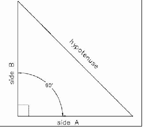
Pythagorean Theorem - Hypotenuse² = side A² + side B²
For our purposes, the hypotenuse is the throw distance, side A of the right triangle is the setback distance from the subject and side B is the elevation (trim height minus the platform height and the height to the middle of the subject). So our equation becomes:
Hypontenuse² = A² + B²
Throw distance² = setback² + elevation²
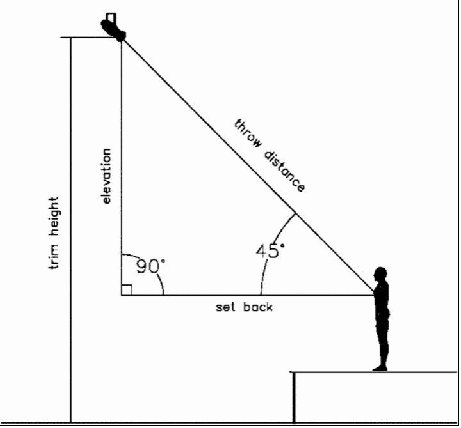
Figure 32 - The throw distance is the hypotenuse, side A is the setback and side B is the elevation.
In a 45 degree right triangle the two sides are equal in length. So the setback distance should be equal to the elevation in our set up. We know that our trim height is limited by the ceiling height and we’re guessing that we can trim at no higher than 22.5 feet. If we subtract the height of the platform (3’) and the height from the platform to the center of the subject (4’ 6”), then that gives us an elevation of 15 feet.
Now we can plug in some numbers:
(Throw distance) ² = (setback)² + (elevation)²
Throw distance = square root [(setback)² + (elevation)²]
Throw distance = square root [(15)² + (15)²]
Throw distance = square root [2 × (15)²]
Throw distance = square root [450]
Throw distance = 21.21 feet
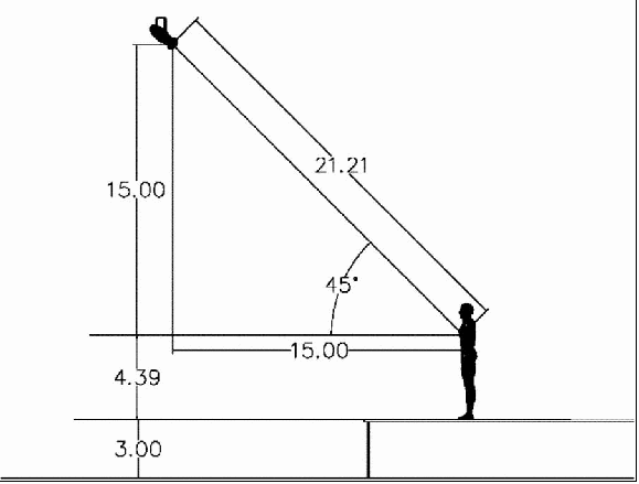
Figure 33 - With a 25' ceiling, the front light might trim at about 22.5', meaning the throw will be less than 20 feet with a three-foot stage.
Note that we can easily figure the setback distance by subtracting the height of the target off the floor from the trim height. With that bit of information, you should be able to walk into any room, measure the ceiling height, and calculate roughly where the front of house truss should be rigged.
Now that we know our throw distance, we have to find a lens that sufficiently covers the acting area and provides enough illuminance to meet our requirements. Most fixtures have some means of varying the beam and/or field angle. Sometimes the lens is replaceable and sometimes it is an adjustable zoom lens. Either way, we will be looking for a lens or zoom setting that is wide enough to cover the acting area but not so wide that it spills onto the entire platform and everything around it.
From our example above, we’re looking for a lens that provides a 10’-wide beam at about a 21’ throw. With a little experience, we will be familiar with which lens sizes are available for the type of fixture we want to use and we will be able to make an educated guess as a starting point for the lens size that will best fit our needs. In this case, we’ll start by looking at a 36 degree lens. Why a 36 degree lens? Because 21’ is a relatively short throw distance and we happen to know that 36 degrees is a standard lens size for a very common ERS fixture – the ETC Source Four. If we want to use another brand, like an Altman Shakespeare, we would start with a 40 degree lens.
The photometric data for a Source Four 36º can be found on the manufacturer’s web site (www.etcconnect.com). It tells us that the candlepower, or luminous intensity, is 82,000 candelas with a 750-watt HPL lamp. But average rated life for that lamp is only 300 hours, which is on the lower end of the scale. If the lights are on an average of 25 hours per week, then they would last an average of 12 weeks, which is far too often to be changing lamps. We would prefer a lamp with a much longer lamp life, so we might choose the HPL 575/115X, which has an average rated life of 2,000 hours.
That’s not to say that it’s a true average. Lamp manufacturers have their own method of rating lamp life “averages.” They set up a sample of lamps, typically about 100 of them, and the run them until 50% of them have failed and they record the time it took to reach that condition. That’s what they use as the average lamp life.
As with most things in life, there is a tradeoff that comes with choosing a lamp with longer life. Longer life lamp also comes with a lower luminous intensity, so we have to account for that in our illuminance calculations. If we look at the photometric data for the HPL 575/115X lamp, it gives us a multiplying factor (MF) of 0.66. That means that the luminous intensity figure given has to be de-rated by a factor of 0.66, so the luminous intensity for that lamp is actually 54,120 candelas.
Luminous intensity is a measure of how strong a light is in a certain direction. It’s related to the illuminance, but it’s not the metric we’re looking for. We need to calculate the illuminance, which is a measure of how much light is falling on a certain area at a given throw distance, by using the inverse square law.
Illuminance (footcandles) = luminous intensity (candelas) ÷ [throw distance (feet)]²
Illuminance = 54,120 ÷ (21.21)²
Illuminance = 120.3 footcandles
The calculation is based on ideal conditions with a new lamp at rated voltage. In practice, lamps lose light output as they age. The quartz envelope of the lamp gradually loses its crystalline structure through repeated heating and cooling cycles and becomes opaque. This is known as devitrification.
Also, some of the voltage is “dropped” across the wires and components in the circuit feeding the lamp, so that the applied voltage is sometimes less than the supply voltage. The longer the circuit, the greater the voltage drop. Some lamp manufacturers account for that by rating lamps for 115V in North America. But if the applied voltage is less than the rated voltage of the lamp, the light output drops exponentially.
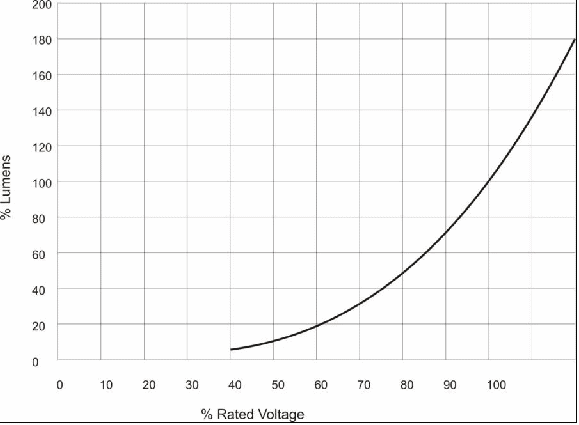
Figure 34 - Applied voltage versus lumen output of a lamp.
Therefore, it is a good idea to take this into account and de-rate our illuminance calculation by 10% or 20%. Still, that gives us between 96 and 108 footcandles, so we have to decide if that’s sufficient for our purposes. If not, then we have several options: we can change to a more narrow lens and add more acting areas to compensate; we can switch to the shorter life 575-watt lamp with more luminous flux; we can switch to a more powerful 750-watt lamp (although these are not available in a longer life version); or we can double up on fixtures and use two key lights for each acting area. The last option, albeit more expensive, is a good fail-safe measure. It provides redundancy so that in the event that one lamp fails during a service then you still have some light on the subject. If we decide that we can live with 96 footcandles after de-rating the illuminance calculation, then we will accept the 36 degree lens and move on.
In some cases the photometric data is provided in the form of a chart instead of the total luminous flux. These charts typically show the illuminance and beam width or field width at periodic throw distances, e.g., 10 feet, 20 feet, 30 feet, etc. If it shows the exact throw distance we happen to be looking for then it’s easy to evaluate our luminaire and lens choice. If not, then we can either extrapolate, or we can work backwards from one of the data points to calculate the total luminous flux and then work forwards to calculate the illuminance.
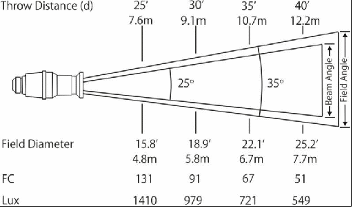
Figure 35 - Photometric chart showing field diameter and illuminance at periodic throw distances. You can use the inverse square law to convert the given data to any throw distance.
Suppose, for example, a photometric chart indicates that the illuminance is 131 footcandles and the field width is 15.8’ with a throw of 25’. But we want to know the illuminance and field width with a throw distance of 21.21’.
By using the inverse square law, we can figure out the total luminous flux:
Illuminance (footcandles) = luminous intensity (candelas) ÷ [throw distance (feet)]²
Luminous intensity = illuminance × (throw distance)²
Luminous intensity = 131 × (25)² = 81,875 candelas
If we looked at the photometric data on the manufacturer’s web site, we may have noticed that we could have taken a short cut. Below the photometric chart it says, “For beam diameter at any distance, multiply distance by .45.” This works because the formula for the tangent of half of the beam angle is the opposite side (half of the beam width) times the adjacent side (the throw distance). So the beam width is 2 x Tan(12.5°) = .45.
By the same token, if we are using a CAD design software tool like WYSIWYG, LD Assistant or VectorWorks, then the software will do some of the calculations for us. But regardless of the tools you have at your disposal, we should know how to derive the calculations. Once we understand the relationship between the lighting metrics, we can develop an intuitive feel for the numbers and our design will go much faster and turn out much better.
Once we know the luminous intensity, then we can figure out the illuminance at the throw distance in which we’re interested.
Illuminance (footcandles) = luminous intensity (candelas) ÷ [throw distance (feet)]²
Illuminance = 81,875 ÷ (21.21)²
Illuminance = 182 footcandles
Next we need to check to make sure the lens we are considering covers the acting area sufficiently. Ideally, we want the beam width to be the same width as the acting area so that when it overlaps with the adjacent beam it will cover the area uniformly. If we can’t match it exactly then it’s better to make it slightly wider than to make it slightly narrower because that will provide better uniformity across the platform.
We can use a simple trigonometric formula to calculate the beam diameter since we know the throw distance and the beam angle of the fixture we selected. The formula we’ll use is one for tangents. The tangent of an angle is equal to the side opposite the angle divided by the hypotenuse of the triangle.
Tangent Ø = opposite side ÷ adjacent side
Notice that the formula uses the hypotenuse, which only works for a right triangle. But the beam angle of a luminaire is not a right triangle. We can, however, turn it into two right triangles by drawing a line down the middle of the beam as shown in the illustration below.
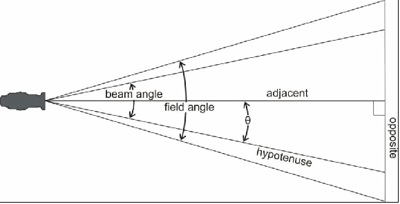
Figure 36 - By drawing a line down the center of the beam we can create two right triangles in order to find the field diameter at a given throw distance.
Now we have two equal right triangles, each of which is half the beam angle of the lens we are considering. If we look at the photometric data we can find the beam angle for a Source Four 36º fixture, which is 25 degrees (the field angle is 35 degrees). Using the formula for tangents, we can now plug in the values for the angle and the adjacent side. Notice that the adjacent side is our throw distance. (You’ll need a calculator with trigonometric functions to do this calculation.)
Tangent Ø = opposite side ÷ adjacent side
Tan (1/2 beam angle) = X ÷ throw distance
X = Tan (12.5º) × 21.21’
X = 4.7 feet
Note that the value of X is only half the beam diameter, so we need to multiply it by 2 to arrive at the final value.
Beam diameter = 2 × X = 9.4 feet
Concepts:
The Pythagorean Theorem, which defines the relationship between the length of the sides of a right triangle, can be used to find the throw distance if we know the trim height and the height of the platform.
Given the throw distance and the luminous intensity, we can use the inverse square law to calculate the illuminance.
When we use the manufacturer’s photometric data, we should take into account lumen maintenance due to devitrification and de-rate our calculations.
The formula for tangents can be used to find the beam diameter at a given throw distance.
Formulas:
Throw distance² = setback² + elevation²
Illuminance (footcandles) = luminous intensity (candelas) ÷ [throw distance (feet)]²
Illuminance (lux) = luminous intensity (candelas) ÷ [throw distance (meters)]²
Tangent Ø = opposite side ÷ adjacent side
Words to know:
ellipsoidal reflector spotlight (ERS) - a luminaire in which the reflector geometry is a revolved ellipse, has a focal plane and produces a hard-edged beam
dichroic filter - an optical thin-film that separates light based on wavelength or color
trim height - the vertical distance from the floor to the rigging point in a lighting system
Pythagorean theorem - a formula describing the relationship between the three sides of a right triangle
hypotenuse - the longest side of a right triangle, which is also the side opposite the right angle (90 degree angle)
right triangle - a triangle in which one of the three angles is a right angle (90 degree angle)
setback - in a lighting system, the distance from the subject to the vertical plane in which a light is rigged, or the horizontal distance from the subject to the light
elevation - in a lighting system, the vertical distance from the subject to the height of the light
candlepower - a unit of measure of luminous intensity in candelas
devitrification - the process by which glass loses its crystalline structure and becomes opaque through repeated cycles of heating and cooling
de-rate - the practice of lowering a value to allow for real-world factors
tangent - a trigonometric function equal to the ratio of the side opposite the angle in question and the hypotenuse
raceway - a long metallic, rectangular electrical enclosure with wiring and electrical connectors used for power distribution
In the above example, we can cover 9.4 feet uniformly at about 120 footcandles (with new lamps) for every x number of fixtures minus one. For example, five of these lights at this throw would give us 37.6’ of uniform coverage [(5 -1) x 9.4’ = 37.6’].

Figure 37 - Five fixtures with an ideal blending distribution and a beam width of 9.4' will cover 37.6' uniformly.
If we have a 40-foot-wide platform, then we would need more than five front lights to cover it completely. Therefore, we have a design decision to make; we can either use six fixtures and shutter cut the spill on either side of the platform, or we can use five fixtures and sacrifice some uniformity at the extreme ends of the platform. In this case, since five fixtures will cover 37.6’ uniformly, 1.2’ on either end of the platform will have some fall-off. It might be a safe bet that the subject won’t spend a lot of time standing in the outer 1.2’ of the platform. If so, then the fall-off outside of the peak of the beam, which is 4.7 feet (half of 9.4), will illuminate them. So five Source Four 36° fixtures will probably supply enough illuminance and uniform wash for the job and cover the front light.
Alternatively, we could move the FOH truss back to widen the beam enough to cover the entire platform uniformly. But we have to be mindful of the inverse square law because the intensity will drop off exponentially as we increase the throw distance. To calculate how far we would have to move the truss back to cover 40’ of the platform uniformly, we start with the formula for tangents. But this time instead of plugging in the value for half of the beam angle and the throw distance, we need to plug in the value for half of the beam angle and half of the desired beam diameter. That’s because we know that to cover a 40’ platform we want to use five lights with a 10’ beam diameter. We begin as follows:
Tangent Ø = opposite side ÷ adjacent side
Tan (½ beam angle) = (½ beam diameter) ÷ throw distance
Throw distance = (½ beam diameter) ÷ Tan (12.5º)
Throw distance = (5’) ÷ .22 = 22.6 feet
Now that we know the throw distance we can use the Pythagorean Theorem to find the setback distance.
(Throw distance) ² = (setback)² + (elevation)²
Setback = square root [(throw distance)² − (elevation)²]
Setback = square root [(22.6)² − (15)²]
Setback = square root [283.5]
Setback = 16.8’
So by moving the FOH truss back 1.3’ from a 15’ setback to a 16.8’ setback we can increase the beam width to 10’. Now let’s check to see how that affected our illuminance by using the inverse square law.
Illuminance (footcandles) = luminous intensity (candelas) ÷ [throw distance (feet)]²
Illuminance = 54,120 ÷ (22.6)²
Illuminance = 106 footcandles
Comparing it to our previous result of 120.3 footcandles, we can see that we lost 14.3 footcandles, an amount that is almost imperceptible to the human eye. Again, to account for lumen depreciation, we should de-rate the illuminance by about 10% to 20%. We end up with 84.8 to 95.4 footcandles. If we’re happy with that figure then we can move on. Otherwise, it’s back to the drawing board.
It is important to note that increasing the setback decreases the vertical angle of projection, which changes the look of the lighting. Remember, a lower angle of projection reduces the size of the shadows in the eye sockets and under the nose and jowls.
But it’s not a good idea to decrease the setback and move the lights closer to the platform with the same trim height because that would increase the vertical angle of projection to more than 45 degrees. That would create problems with harsh shadows. Also, remember not to decrease the angle too far below 45 degrees because the glare will fatigue the eyes of the subject and it will place shadows on the backdrop.
To summarize, these are the steps we took to arrive at our calculations:
We estimated the maximum trim height we could achieve given our ceiling height and the overhead for the rigging.
We selected a fixture to use as a starting point for our design.
We used the Pythagorean Theorem to calculate the throw distance based on the trim height with a 45 degree projection.
We looked up the luminous intensity (candelas) in the photometric data on the manufacturer’s web site and used the inverse square law to calculate the illuminance at our throw distance.
We looked up the beam angle in the photometric data and calculated the beam diameter at our throw distance using the formula for tangents.
We evaluated the data to see if it fit our calculation and found that it was close.
We adjusted the setback to match the width of the platform and recalculated the illuminance at the new throw distance.
Concepts:
If we know the beam angle and the beam width at a given throw distance, we can determine how many lights would be needed to uniformly cover the stage with front light.
Words to know:
shutter cut - the act of controlling the beam of an ellipsoidal reflector spotlight with the shutters
front of house (FOH) - the area downstage of the proscenium and stage including the seating area or the control booth from where the lighting is operated
lumen depreciation - the loss of light output over time due to devitrification and bulb wall blackening
computer-aided design (CAD) - a software program that facilitates electronic drafting used to draw designs
WYSIWYG - the trade name of a CAD, paperwork and visualization software package made by Cast Software
LD Assistant - the trade name of a CAD, paperwork and visualization software package made by Design & Drafting
VectorWorks - the trade name of a CAD and paperwork software package made by Nemetschek
In a 4-point lighting system, each acting areas should have two fill lights, one on either side of the platform at a 90 degree angle to the key light. Ideally, the fill lights will be located at a 45 degree or lower vertical angle from the horizon.
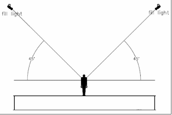
Figure 38 - In a 4-point lighting system, the fill light should be located on either side of the subject at a 90 degree angle from the front light and 45 degrees above the horizon.
The fill lights can be the same type of lights that we use for the key light. But the lenses should be sized accordingly, so that the illuminance and beam width fit the throw distance. The purpose of the fill lights is to soften the shadows created by the key lights, and the illuminance can be equal to or slightly less than the key lights. Adding frost filters to the fill lights softens the edge and helps blend them with the key light. Remember that when you use a frost filter it drops the intensity and widens the field angle. How much the intensity drops and the field widens depends on the type of frost filter used.
The uniformity and beam control are not as critical with backlighting, so PAR cans or compact filament PARs (e.g., ETC Source Four PAR) work well for this application. They are relatively inexpensive, readily available, rugged and lightweight. For most any lighting design, whether it’s a 3-point or a 4-point lighting system, each key light should have one backlight located directly behind the subject opposite the front light, and they should be rigged at a 60 degree angle, or higher, from the horizon. Remember to use barn doors to prevent light spill onto the first few rows of the audience.
Concepts:
In a 4-point lighting system, two fill lights should be located on either side of the subject at a 90 degree angle to the front light and 45 degrees above the horizon.
The backlight should be located directly behind the subject and at least 60 degrees above the horizontal.
In our 4-point lighting plot, as shown below, the fill lights are located in rows parallel to the lip of the platform and centered over the acting areas.
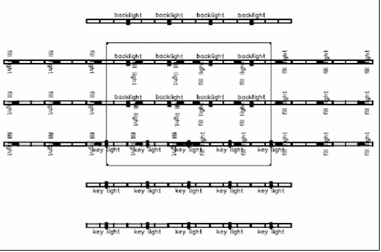
Figure 39 - If we locate our fill lights on either side of the subject at a 90 degree angle to the key light and a 45 degree angle above the horizon, we end up with a row of fill lights parallel to the lip of the platform, one for each row of acting areas.
In a television studio or a theatre there might be a pipe grid to accommodate a hang like this, but in a sanctuary we have to be more concerned about lines of sight and aesthetic appearance. Consequently, we often have to compromise our hanging positions to suit the needs of the congregation. We can modify the lighting plot to accommodate a simplified rigging system by consolidating our lighting positions and reduce the number of rows of truss. By moving all of the key lights on the second FOH truss (closer to the platform) to the first FOH truss (farther from the platform) and moving all of the backlights on the upstage truss (the top truss in this plot) to the next closest truss, we can reduce our truss count from six to four, as shown in the figure below.
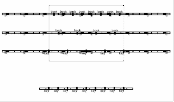
Figure 40 - The 4-point lighting system using six truss positions in the figure above can be consolidated on four spans of truss as shown here.
We can eliminate more truss by adding side positions stage right and stage left and moving the fill light off the platform. This is a common lighting configuration that you might see in a number of sanctuaries.
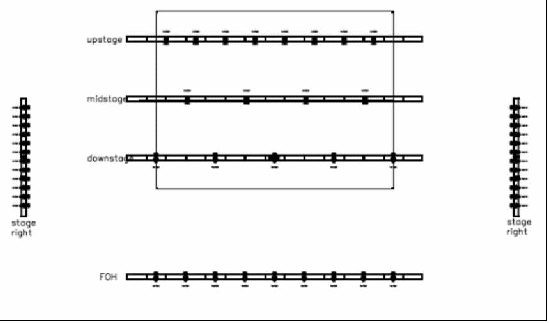
Figure 41 - We can further reduce our trussing requirements in a 4-point lighting system by using side truss positions stage right and stage left. This is a common lighting plot used in many productions.
In this configuration the fill lights are not at a perfect 90 degree angle, they are throwing a longer distance, and they are at a lower angle than 45 degrees above the horizon. As it turns out, the lower angle doesn’t adversely affect the subject because it’s side light and not front light. In addition, it helps model the subject better. In many dance productions, the side light is parallel to the stage because it better accentuates the human form. If the fill lighting positions have to be cheated, cheat them more downstage than upstage. If they are rigged past the 90 degree mark relative to the subject, then they become backlight and not fill light.
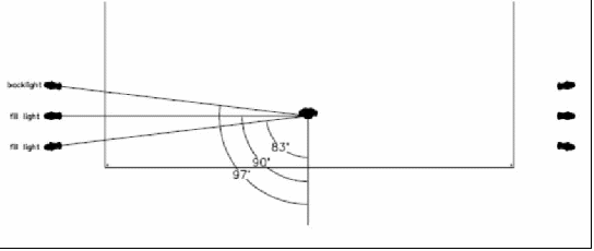 Figure
42 - Repositioning the fill light by moving them downstage is
acceptable; moving them upstage makes them more of a
backlight.
Since the throw distance is longer from the side truss positions, the lens sizes should be re-evaluated to determine whether or not they should be changed. Keep in mind that the intensity of the fill light can be less than that of the key light by about 25% to 50%.
When we relocate our lighting positions, we have to take care to resize the lenses to maintain the required beam diameter and illuminance. In theory, resizing the lens to match the original beam size with a different throw distance should yield the same illuminance because of the conservation of energy. The conservation of energy says that energy can neither be created nor destroyed; it can only change forms. In this case, we use the same amount of light, which is a form of energy, and we are using a different lens to project it a longer way. But as long as the beam ends up with the same diameter, then the same amount of light is distributed over the same area.
In practice, however, we find that the inefficiency of the optics comes into play; in general, the wider the beam angle, the less efficient the optics. Consequently, we end up with some variation in the output that is dependent on the lens angle, as illustrated below. Note that each of the fixtures has a different beam angle and a different throw distance, but the beam diameter is the same in each case. In a perfect world we would expect the illuminance to be equal, but the optics are less efficient as the beam angle gets wider.
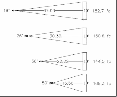
Figure 43 - In theory, the same fixture and lamp with a variety of lenses and throw distances should yield the same illuminance when it is distributed over the same area. But in practice we find that the wider the lens, the less efficient the instrument is.
When we are evaluating how to adjust our light plot, we need to keep these things in mind:
Increasing the throw distance will also increase the beam size. When it comes to front lighting, excessive overlapping with the adjacent lights produces a more uniform wash than insufficient overlapping.
The inverse square law says that as you increase the throw distance, the intensity will fall off exponentially. That helps give us separation between the foreground and the background because the background has less illuminance than the foreground. However, as we increase the throw distance, the difference in intensity between the foreground and the background becomes less pronounced. That’s because the ratio of the separation distance to the throw distance is much smaller than when the throw distance is short. So a short throw distance provides more background separation than does a long throw.
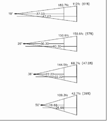
Figure 44 - The fall off in intensity at a fixed distance behind the subject becomes less pronounced as the throw distance increases.
If we can’t rig a light in the ideal position and we have a choice between a shorter throw distance and a longer throw distance, then the trade-offs to consider are: glare, harsh shadows, separation of the background, lens efficiency, and overlapping.
Concepts:
Sometimes the ideal lighting positions have to be compromised by consolidating truss positions for the sake of line of sights and aesthetics.
Lighting positions can be moved to accommodate the rigging with little consequence as long as the lens size is reevaluated for coverage and illuminance and close attention is paid to the angles of projection.
Moving fill light downstage is acceptable; moving fill light upstage and beyond a 90 degree angle from the front light makes it a backlight.
Energy can neither be created nor destroyed, but it can change forms.
The wider the beam angle, the less efficient the optics.
Increasing the throw distance is preferred to decreasing the throw distance as long as the minimum acceptable illuminance is met.
Excessive beam overlapping is preferred to insufficient overlapping as long as the minimum acceptable illuminance is met.
A short throw gives better separation between the foreground and the background.
Understanding the McCandless method of 3-point lighting and how to adapt it for a 4-point lighting system for video is crucial to understanding lighting design. Once we master the fundamentals then we can begin to apply them to real life situations and adapt them to your unique circumstances.
Up until now, we have talked about designing for visibility, modeling, uniformity and to meet the illuminance requirements. These are the broad strokes of lighting design. In subsequent pages in this book we will cover the more esoteric aspects of lighting design. Remember that lighting design is not an exact science and these are principles and guidelines to help us get the most out of a lighting system. It’s up to us to study, understand and internalize these principles and use them in creative ways to make them work for our application.