Ports, Pins, and Plug-Ins
In This Chapter

- The Raspberry Pi’s ports and pinouts
- Connecting various equipment
- The Raspberry Pi’s component
We’ve had a quick look at the basics of everything on the Raspberry Pi, but it’s time to dig a little deeper into its different ports and pinouts.
When you look at your Raspberry Pi, you probably recognize ports like the HDMI or USB plugs. But you’ll also notice some strange pins sticking out of it. These are the GPIO pins. These GPIO plugins aren’t as obvious to use as something like a USB port, so they require a bit more in the way of explanation.
After you understand the GPIO pins, it’s time to connect your Raspberry Pi to the peripheral equipment you want to use with it. From there, it’s almost time to boot up your Raspberry Pi for the first time.
In this chapter, I demystify all the ports on your Raspberry Pi and explain what each is used for.
The Raspberry Pi has a few easy to recognize ports, like USB, HDMI, and Ethernet, but it also has a pinout section that might be a bit confusing to look at. Thankfully, these pinouts are pretty easy to understand once you see a diagram showing what they connect to. First, let’s take a look at all the ports.

HARDWARE HELPER
The Raspberry Pi has all kinds of extra peripherals you can attach to it, including a camera and a display. Both of these types of peripherals get their own port on the board. (I talk about these more in-depth in Chapter 21.)
Raspberry Pi Ports
Your Raspberry Pi has a number of different ports you can use to connect various components to it. Here’s a rundown of each of these ports:
USB ports: The USB ports on your Raspberry Pi are where you connect accessories like a keyboard, mouse, Wi-Fi adapter, and more. The Model A+ has one, the Model B has two, and Models B+ and 2 have four.
Ethernet port: The Ethernet port is where you connect an Ethernet cable to access the internet. The Model A+ does not have an Ethernet port.
HDMI port: You connect an HDMI cable here to output a HD video and audio signal to a monitor or television.
Composite video port (Models A+ and B): You can use an RCA cable here to connect your Raspberry Pi to a composite TV or monitor.
Audio jack/3.5mm video port (Models A+, B+, and 2): On Models A and B, you use this jack or port to output audio through a 3.5mm cable. On Models A+, B+, and 2, it’s used for both audio and video.
Digital Serial Interface (DSI): This is another video output port, made for direct connections. This is a bit more advanced. If you were to use a small LCD screen with your Raspberry Pi instead of a monitor, you could use this port.
Camera Serial Interface (CSI): This interface is for the Raspberry Pi camera. The camera has a cable that connects directly to this port.
Joint Test Action Group (JTAG) Headers: This port is for connecting your Raspberry Pi to a debugger. This is only for advanced users, so I won’t be covering it in much detail here.
That’s it for your ports. Now let’s take a closer look at the GPIO pins.
Pinouts are the little pins you see on your Raspberry Pi. These are GPIO (general-purpose input/output) pins that enable you to connect your Raspberry Pi to more devices than just the ones listed in the preceding section.
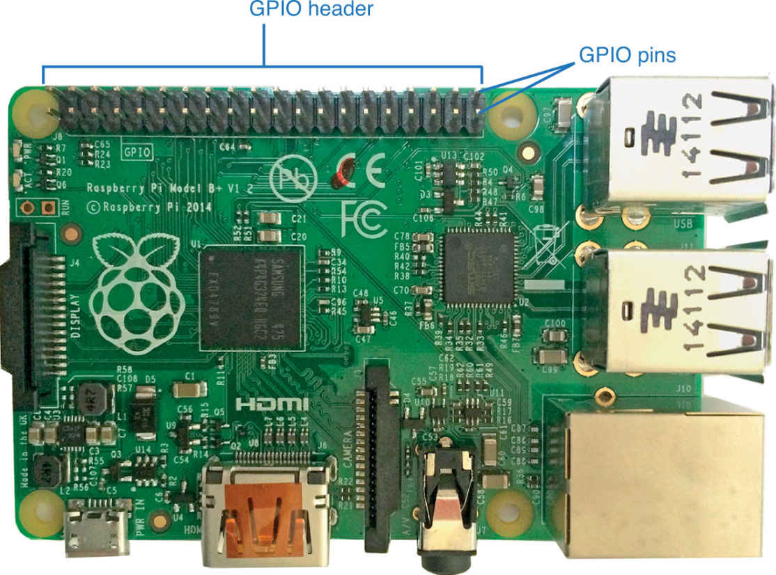
On all Raspberry Pi models, the GPIO header (the black bar), holds the GPIO pins.
GPIO pins connect your Raspberry Pi to various hardware components, enabling you to send inputs and outputs from the Raspberry Pi. Essentially, the GPIO pins make it so you can directly connect your Raspberry Pi external hardware.
Typically, you’ll do this with a solderless breadboard. A breadboard features a board of terminal strips upon which you can link two wires together without soldering or tying the cables together. They’re often used to prototype electronics.

DEFINITION
A solderless breadboard is a prototyping device that enables you to connect two wires without soldering or tying them together. You can purchase a solderless breadboard for around $5 from many electronics shops.
Each section of the GPIO pins does a different thing. Some are for inputs, and other are for outputs. Some are powered, and others are not. You’ll only need the latter if you’re programming external hardware (which we won’t be doing in this book), but it’s good to know what they’re used for and where they are if you decide to do any advanced projects. The GPIO layout is a little different between Models B+ and 2 and older versions.
Before we get to that, let’s define some of the shorthand used in the pin charts:
SDA (serial data line) and SCL (serial clock line) are inter-integrated circuits. They’re simple, two-wire interfaces. The SCL, the clock line, is used to synchronize data transfers on a timer. SDA is the data line that does the same thing.
UART stands for universal asynchronous receiver/transmitter. This means it takes individual bits sequentially. Basically, one bit is sent over at a time in a long row.
Ground is the reference point for the electric circuit. Think of it as 0. It works the same way as the ground on your car’s battery or in your household wiring.
MOSI stands for master out, slave in. This sends a master signal out of your Raspberry Pi and receives data from the slave. A slave could be a hard drive, a robotic controller, or pretty much anything else with an output.
MISO stands for master in, slave out. It works the opposite way as MOSI.
SCLK (serial clock) is a clock line. It’s generated by the master and drives communication in both directions.
This can be a bit complicated, but don’t worry. Although it’s important for you to know, you won’t really need to use it very often.
GPIO Pin Locations
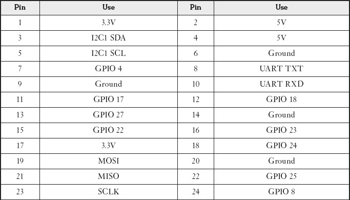
Now let’s take a look at which pin does what on the Raspberry Pi. Here’s a chart to get a handle on what each does.

PI POINTER
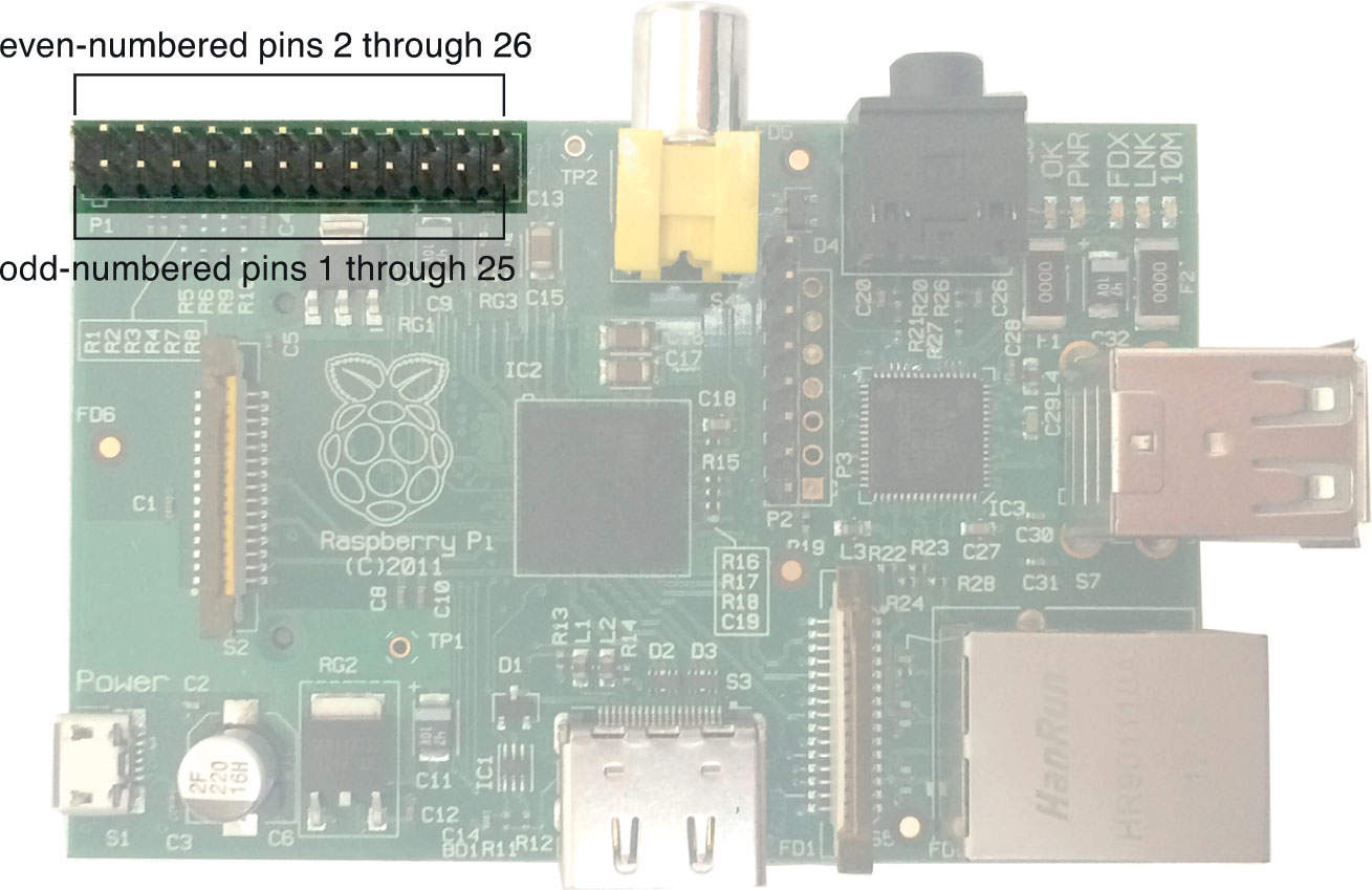
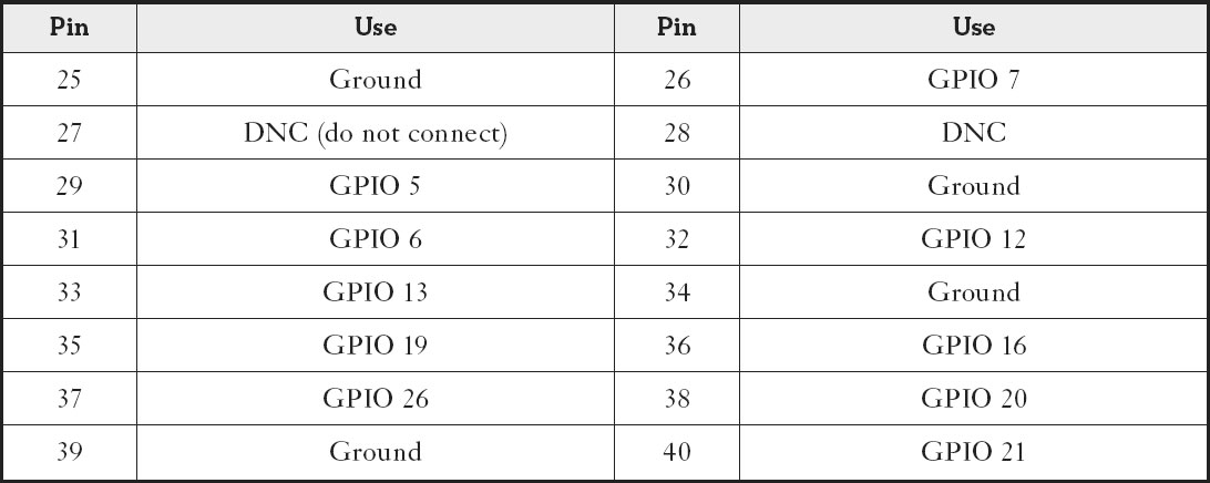
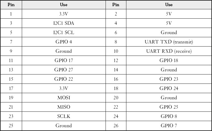
The GPIO pins are arranged in two columns and numbered from the top left, across to the right, down to the left, and so on. The “Pin” columns in following tables mimic the layout of the pins in the GPIO header on your Raspberry Pi.
The GPIO pins on the Model B.
Model B GPIO Pin Uses
The Model B+ is a little different because it has more GPIO pins. Still, the setup is basically the same as what’s on the Model B.
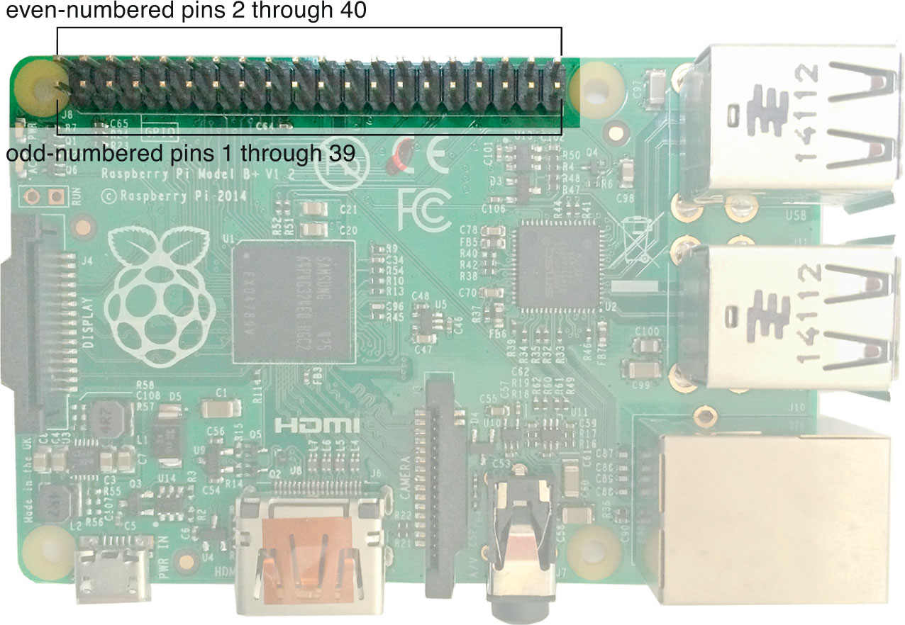
The GPIO pins on Models A+, B+, and 2.
Models A+, B+, and 2 GPIO Pin Uses
That’s it for GPIO. It can be a bit confusing and difficult to really understand until you actually need it. Don’t worry though, if you do end up using these pins for a project, it becomes a lot less confusing when you start working with them.
Connecting Equipment
Now that you’ve got a basic understanding of how everything on the Raspberry Pi works, it’s time to start plugging in components. This part’s pretty self-explanatory, but let’s walk through the process so you know what you’re doing.
Adding Accessories
If you happened to get a dedicated display for your Raspberry Pi or the camera connection kit (I talk about these more in Chapter 21), you can connect them to your Raspberry Pi now.
The camera attaches to the camera connection, the CSI, using the ribbon cable that came with it. Just line it up and clip the ribbon on the Raspberry Pi. Plug the end into your camera, and you’re good to go.
Likewise, if you’re using a dedicated display, you can connect the ribbon cable from the display into the display connection, the DSI, the same way.
If you’re not using either, you can skip ahead and plug in your other cables.
Now it’s time to get your Raspberry Pi plugged in and running. Here’s what you need to do:
- Plug your USB keyboard and USB mouse into the USB slots. If you’re using the Model A+, you’ll need to either use a USB hub or a keyboard that has an extra USB input on it.
- Connect the HDMI cable to the HDMI input or the composite cable to the RCA input. If you have a Model A+, B+, or 2, connect your 3.5mm to RCA converter into the 3.5mm jack.
- Connect your video cable into your TV or monitor.
- Plug the Ethernet cable into the Ethernet jack on your Raspberry Pi and then the Ethernet port on your modem or router. If you’re using the Model A+, you’ll need a USB Wi-Fi adapter for internet access.
You have two more items to plug in—the SD card and the power adapter.

PI POINTER
Don’t worry too much about the order you plug in your accessories. The only thing that really matters is that the power cable gets plugged in last. The Raspberry Pi doesn’t have a power switch, so plugging in the power supply turns it on automatically. You don’t want to do this until everything is set up and ready to go.
Connecting the SD Card
Plug your SD card into the slot on the bottom of the Raspberry Pi. Just slide the card in until it clicks into place.
However, before you do that, you’ll need to set up the SD card with an operating system. We take a look at the various options in the next chapter.
Powering On
Last but not least—and after you’ve outfitted your SD card with your desired operating system—it’s time to power up your Raspberry Pi. Simply attach the power cord to your Raspberry Pi and then plug the other end into an electric outlet.
- The Raspberry Pi has myriad different kinds of inputs and outputs for connecting various devices.
- The GPIO pins are great for connecting your Raspberry Pi to external hardware, but you won’t need to use them for most beginner projects.
- To connect your Raspberry Pi to your accessories, you need a USB mouse, a USB keyboard, a TV or monitor that supports either HDMI or composite video, and a modem with an Ethernet port.
- The SD card port is located on the bottom side of your Raspberry Pi.
