Chapter 2. What is a Cisco network?
Every organization’s most valuable traffic passes through two types of networking devices: routers and switches. Cisco makes some of the most popular, dependable routers and switches around, so most organizations standardize on Cisco for these devices. For other networking devices like firewalls and wireless access points, they may go with Cisco or they may choose a different brand altogether. But as long as the network uses Cisco routers and switches, you can consider it a Cisco network.
There’s no requirement that you must use Cisco-branded routers and switches. You can use a Cisco switch with a Juniper router, and they’ll work together just fine. You can use a Cisco router with a Juniper switch, and that will work fine too. But there are a couple of disadvantages to doing this.
First, the steps to configure a Cisco device are substantially different from the steps to configure a Juniper device. The commands, terminology, and order in which you do things are different. Administering a mixed network requires knowing how to configure both platforms and getting them to interoperate. This book addresses only the Cisco side of things.
Second, if you have a problem on your network and aren’t sure whether it’s the router or switch, you have to open support tickets with both companies. In the worst case, you get a lot of finger-pointing between the companies. In the best case, you get a delayed resolution.
Mixing different brands of routers and switches isn’t a good idea. That’s why the vast majority of organizations use Cisco for both. It’s just easier. But if you have a mixed environment, you can still use this book to learn how to administer the Cisco routers or switches on your network. Just be aware that for the purposes of this book, a Cisco network always consists of Cisco routers and switches.
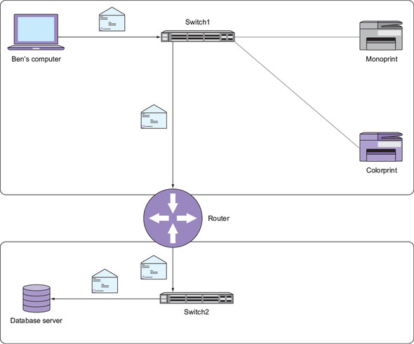
In figure 2.1, my computer needs to send an “envelope” containing some data to the database server. In this chapter, you’re going to learn how the switches and router ensure the data gets to its destination in the most efficient way possible.
Figure 2.1. Switches and a router in a network
2.1. The truth about routers and switches
Newcomers to networking often have two questions:
- What do routers and switches actually do?
- Why do devices have both MAC and IP addresses?
These seemingly simple questions don’t have a straightforward answer. I’ve seen many attempts to answer these questions in a few sentences, and all such attempts invariably cause more confusion than they clear up.
The truth is that routers and switches were born out of necessity rather than practicality. In principle, neither device is particularly elegant or clever, although Cisco has done some clever things to make them perform better. Like most technologies, routers and switches came about because of questionable decisions that were made decades ago.
Later technology is usually built on earlier technology. For instance, e-books borrow concepts such as pages and bookmarks from traditional printed books. Imagine explaining the page concept to someone who is used to reading scrolls but has never seen a traditional printed book. How would you do it? Before you can explain what a page is, you have to explain why pages exist in the first place.
Similarly, before I can explain what a router or a switch is, I have to briefly explain what problems each was designed to solve. Once you understand that, everything else will fall into place more easily, and you’ll be administering your own Cisco network in no time.
2.2. MAC addresses
A long time ago, some folks decided that all network devices would uniquely identify each other using something called a media access control (MAC) address. A MAC address is 48 bits long and is represented as a string of hexadecimal numbers, like this: 0800.2700.EC26. You’ve probably seen a few of these.
Here’s the interesting part: the manufacturer of each network device assigns it a unique MAC address at the time of manufacture. The rationale behind this is to make it possible to simply plug a device into a network and have it communicate with other devices without having to manually configure anything. That sounds noble, but there’s a rub: because the manufacturer assigns the MAC address, it has no relationship to where the device will physically end up. In that sense, it’s not really an address because it can’t help you locate the device.
Open a Windows command shell and type ipconfig /all. Your computer’s MAC address is listed next to Physical Address. If you have multiple network interface cards (NICs), you’ll see multiple MAC addresses.
A MAC address works like a person’s full name. It’s assigned at birth and makes it easy to identify someone, get their attention in a crowd of people, and even send them a message by calling out their name. If we’re in a large crowd of people, and you need to communicate a message to me but have no idea where I am, you could get on a bullhorn and yell, “Ben Piper, where are you?” If I’m in that crowd, I’ll receive your message.
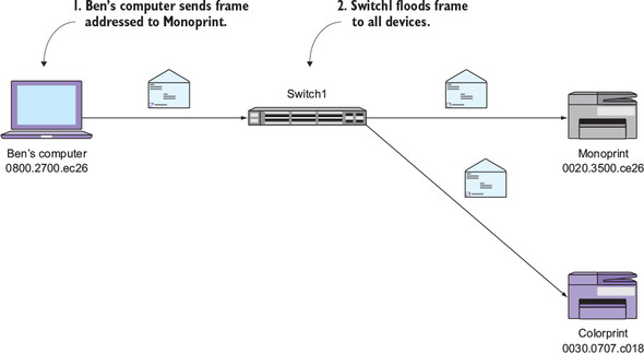
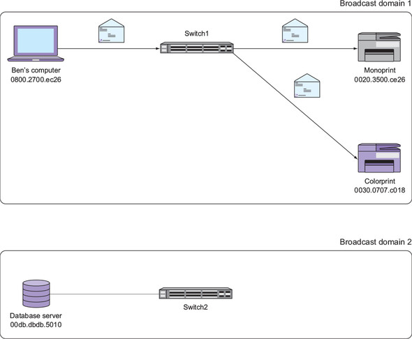
Network devices communicate with each other in a similar fashion, but instead of using full names, they use MAC addresses. Suppose that my computer has a MAC address of 0800.2700.EC26, and it needs to print to a network printer named Monoprint with the MAC address 0020.3500.CE26. My computer and the printer have a physical connection to a device called a switch, as illustrated in figure 2.2. Specifically, my computer and the printer are physically connected to individual Ethernet ports on the switch. Note that unlike a wireless access point, connections to a switch are always physical connections. In this sense, a switch is like a gathering place for network devices. Just as you and I might gather together with others in a crowded outdoor marketplace, network devices gather together on a switch. This collection of connected devices is called a local area network (LAN).
Figure 2.2. Computer and two printers connected to a switch

But here’s the problem: my computer doesn’t know where Monoprint is or if it’s even a part of the LAN—the “crowd” of devices connecting to the switch. MAC addresses, like full names, make good identifiers, but they’re lousy at telling you exactly where a device is. Because of this, my computer has to get on its “bullhorn” and call out to Monoprint using its MAC address.
Each device manufacturer has an organizationally unique identifier (OUI), which is a string of six hexadecimal numbers. The OUI makes up the leftmost part of every MAC address the manufacturer assigns. You can think of the OUI as a person’s surname. Even though it’s assigned “at birth,” devices from the same manufacturer share the same OUI. The rest of the MAC address is assigned sequentially. This is how manufacturers ensure each device’s MAC address is unique.
2.3. The Ethernet frame: a big envelope
My computer creates an Ethernet frame containing its own MAC address as the source and the printer’s MAC address as the destination. Think of the Ethernet frame as the big envelope in figure 2.3 with a return address and a destination address.
Figure 2.3. An Ethernet frame contains source and destination MAC addresses.

My computer places the data it wants to send—in this case, a print job—inside the “big envelope” and sends it to the switch. The switch receives the frame and looks at the destination printer’s MAC address. Initially, the switch has no idea which switch port the printer is connected to, so it sends the frame to every other device plugged into the switch in order to get it to the one device that needs it, the printer. This is called flooding.
In step 1 in figure 2.4, my computer sends an Ethernet frame addressed to Monoprint’s MAC address (0020.3500.ce26). In step 2, the switch floods this frame to all other connected devices.
Figure 2.4. Ethernet frame flooding
2.3.1. When everybody talks, nobody listens
Flooding has an effect similar to that of blasting a bullhorn into a large crowd. Everyone hears you, but for that moment, people in the crowd can’t hear each other. You effectively stop their communication, at least momentarily. Even after you stop bellowing into your bullhorn, it takes a bit of time for the people in the crowd to process your message and realize that they were not the intended recipient. The same thing happens when a switch floods or sends a message to all devices. Those devices won’t be able to “hear” any other devices until the flood is over. And even then, they must process the message to determine whether they need to do anything with it. This phenomenon is called an interrupt.
Although a few flooded frames and interrupts here and there might seem negligible, consider what would happen in a crowd of, say, 1,000 people who each have a bullhorn. Just as you’re ready to get on your bullhorn and send a message to me, someone right next to you gets on their bullhorn and yells out to someone else. After your ears stop ringing, you raise your bullhorn again, only to be once again interrupted by someone else. Eventually, you might get enough of a break to get your message out. But that’s the problem. You’re competing with others for the use of a shared medium, the air. This one-to-many communication method makes it difficult to relay a message to a specific person in a timely manner. And the larger the crowd, the worse the problem becomes.
On a LAN with a few devices, flooding isn’t a problem. On a LAN with hundreds or thousands of devices, it is. But that raises another problem. A network that can’t connect thousands of devices is virtually useless.
2.4. Broadcast domains
Suppose you add another switch named Switch2 to the network topology and connect a database server to it, as shown in figure 2.5. When my computer sends a frame to the server’s MAC address, Switch1 will flood (and interrupt) every device connected to its ports, including Switch2! Switch2 in turn will flood the frame to every other device. In this case, the database server is the only other device connected to Switch2.
Figure 2.5. Second switch extending the broadcast domain
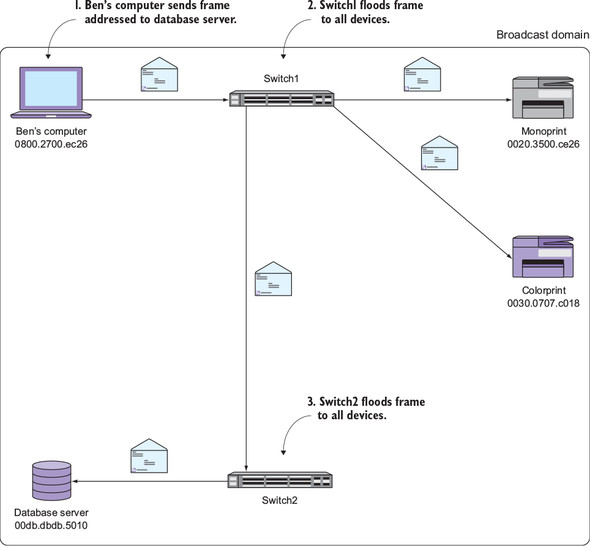
In step 1, my computer sends a frame addressed to the database server’s MAC address (00db.dbdb.5010). In step 2, Switch1 floods this frame to all of its connected devices. Finally, in step 3, Switch2 floods the frame to the database server.
All of these devices that receive the frame are members of the same broadcast domain. A broadcast domain isn’t a thing or a directly configurable setting but rather an emergent property of a network. To better understand this, consider the following analogy.
When you stand alone in the middle of a street, you’re not a crowd. But as a few people gather around you, you become part of a small crowd. As more people gather around you, you become part of a larger crowd. You don’t change, but you become part of a crowd by virtue of how many others gather around you. Similarly, a device becomes part of a broadcast domain by virtue of which devices it receives flooded frames from.
2.4.1. Closing the floodgates: the MAC address table
Flooding is an inevitable side effect of using MAC addresses. Fortunately, switches use a neat little trick to mitigate unnecessary flooding. Whenever a switch receives a frame, it looks at the source MAC address and the switch port it came in on. It uses this information to build a MAC address table.
Cisco sometimes refers to the MAC address table as a content addressable memory (CAM) table, but they’re the same thing.
When Switch1 receives a frame from my computer, it takes note of the source MAC address—0800.2700.ec26—as well as the switch port the frame came in on—FastEthernet0/1. It adds this information to its MAC address table, as shown in table 2.1.
Table 2.1. Switch1’s MAC address table
|
Device |
MAC address |
Switch port |
|---|---|---|
| Ben’s computer | 0800.2700.ec26 | FastEthernet0/1 |
Now suppose the database server sends a frame addressed to my computer’s MAC address. The frame reaches Switch2, which in turn forwards it to Switch1. But this time, instead of blindly flooding the frame to all other devices, Switch1 checks its MAC address table.
It sees that the destination MAC address—0800.2700.ec26—is on FastEthernet0/1, so it sends that frame only out of that specific port; see figure 2.6. This works similarly to an old telephone switchboard, which is where the term switch comes from.
Figure 2.6. How the MAC address table mitigates flooding
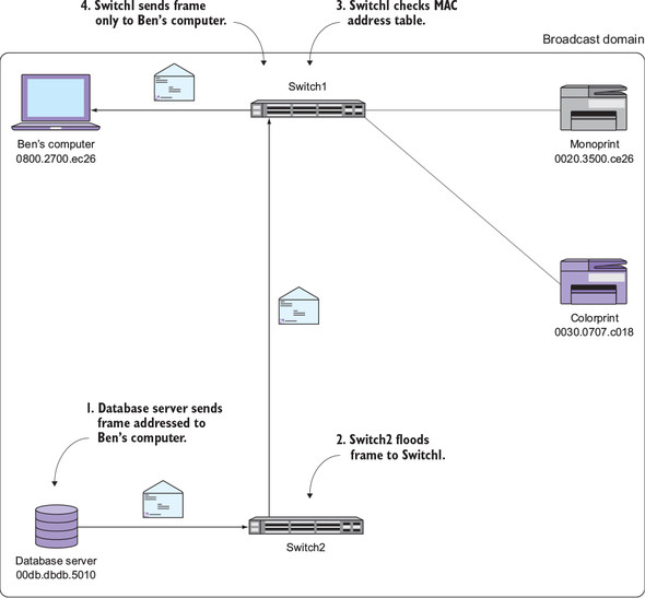
In step 1, the database server sends a frame to my computer’s MAC address (0800.2700.ec26). In step 2, Switch2 floods the frame to Switch1. In step 3, Switch1 consults its MAC address table and finds a corresponding entry for the destination MAC. In step 4, Switch1 sends the frame only to my computer instead of flooding it to all devices.
2.4.2. Breaking up the broadcast domain
As the size of the broadcast domain grows, communication becomes more difficult. Consequently, a broadcast domain containing hundreds of devices performs poorly. But modern organizations require network connectivity among thousands of devices. And just having connectivity isn’t good enough. The network still has to be fast and reliable.
The solution is to limit the size of the broadcast domain. This means breaking it into multiple, small broadcast domains that somehow can still communicate with each other.
Going back to our example, the simplest way to split the broadcast domain is to remove the Ethernet cable connecting Switch1 and Switch2, as shown in figure 2.7. Note that the switches aren’t connected in any way. That’s the easy part. Here’s the hard part: My computer and the database server reside on two separate broadcast domains. There’s no way my computer and the server can communicate. What do you do? You can’t just plug the switches back together because that would re-create the original, single broadcast domain.
Figure 2.7. Two broadcast domains
2.4.3. Joining broadcast domains
In order to join two broadcast domains together without encountering that nasty flooding problem, two things must happen: First, because both broadcast domains are physically disconnected, you need a special device to physically connect them in such a way that flooded frames can’t cross the broadcast domain boundary. Because frames contain source and destination MAC addresses, this device will effectively hide the MAC addresses in one broadcast domain from the MAC addresses in the other.
Second, because MAC addresses in one broadcast domain will be hidden from those in another, you need a different scheme to address devices across multiple broadcast domains. This new addressing scheme, unlike MAC addresses, must not only be able to uniquely identify devices across broadcast domains, but it must also provide some clues as to which broadcast domain each device resides in. Let’s start with the latter.
2.4.4. Addressing devices across broadcast domains
The addressing scheme has to meet some requirements: First, the addresses have to be unique across broadcast domains. A device in one broadcast domain can’t have the same address as another device. Second, the address has to tell us all by itself which broadcast domain it’s a part of. The address should be able to not only uniquely identify a device but also tell other devices which broadcast domain it resides in. This is to avoid that ugly flooding problem. Third, the addresses can’t be “assigned at birth” like MAC addresses. They have to be configurable by you, the network administrator.
Fortunately, you don’t have to look very far. Such an addressing scheme already exists, and you’re already using it.
2.5. Internet Protocol addresses
You already know what an IP address looks like. One of the most common IP addresses is 192.168.1.1. It’s a series of four octets separated by dots, and each octet can range from 0 to 255.
You’ve probably seen these 192.168.x.x addresses pop up in a variety of places. That’s because 192.168.x.x addresses are reserved for use on private networks like your home or business. They’re not globally unique because they’re not reachable via the public internet. But you can still use them to address devices on your own internal networks.
Unlike a MAC address, you can assign any IP address to whatever device you like. You can create your own addressing scheme based on where devices are, not just what they are. Let’s look at an example.
2.5.1. Where are you?
Devices connected to Switch1 are in broadcast domain 1 and devices connected to Switch2 are in broadcast domain 2. You could, then, assign a 192.168.1.x address to all devices connected to Switch1 and a 192.168.2.x address to devices connected to Switch2. Even without looking at figure 2.8, just knowing the IP addresses makes it painfully obvious which broadcast domain each device resides in.
Figure 2.8. Each device has an IP address that corresponds to its broadcast domain.

Note that if you wanted to add a third broadcast domain, you could assign 192.168.3.x addresses to the devices in that domain. The nice thing about using IP addresses is that there’s no practical limit to the number of separate broadcast domains you can address with them.
But at this point, there’s still no connectivity between the two broadcast domains, so it’s only possible for devices to communicate within the same broadcast domain. But that raises this question: Now that each device has both an IP and MAC address, which one will it use to communicate within its broadcast domain?
2.5.2. The IP vs. MAC dilemma
“Why don’t we just use IP addresses instead of MAC addresses?” is a common refrain among IT professionals trying to learn networking. It’s a good question.
After all, MAC addresses aren’t very friendly. They’re hard to remember, mostly meaningless, and difficult (if not impossible) to change. IP addresses, on the other hand, are easy to remember, easy to change, and can be very meaningful with regard to location and function. The winner here is obvious.
So why don’t we just use IP addresses and get rid of MAC addresses altogether? The answer is simple but a bit disturbing.
Network devices within a broadcast domain still have to communicate using MAC addresses. This is a requirement of the Ethernet standard that’s been around for decades. Assigning IP addresses doesn’t change that. Sure, someone could come along and create a new standard that makes MAC addresses unnecessary, but that would require replacing every single device on your network.
In short, MAC addresses are here to stay. That’s the bad news. The good news is that you don’t have to think about them, at least not very often.
2.5.3. Address Resolution Protocol
Remembering both the MAC and IP address of a device is inefficient and wasteful. That’s why almost all networked applications use the IP address and completely ignore the MAC address. The Address Resolution Protocol (ARP) makes this possible.
ARP provides a clever way to map or resolve IP addresses to MAC addresses. The advantage of ARP is that it lets you use human-friendly IP addresses without even having to think about MAC addresses. All network devices made since the mid-1980s use ARP by default, so you don’t need to manually configure it.
Suppose that my computer needs to send another print job to Monoprint. Both devices are in the same broadcast domain, so they’re still going to talk using their MAC addresses. But you, as a network administrator, don’t want to even think about MAC addresses. So you configure my computer to print to Monoprint’s IP address: 192.168.1.20.
Figure 2.9 illustrates how ARP works. My computer sends an ARP request to figure out Monoprint’s MAC address. The request says, “This is 192.168.1.10 and my MAC address is 0800.2700.EC26. Who has 192.168.1.20?” My computer stuffs this ARP request inside an Ethernet frame and sends it to a special broadcast MAC address, FFFF.FFFF.FFFF, as shown in figure 2.9.
Figure 2.9. Address Resolution Protocol request and reply
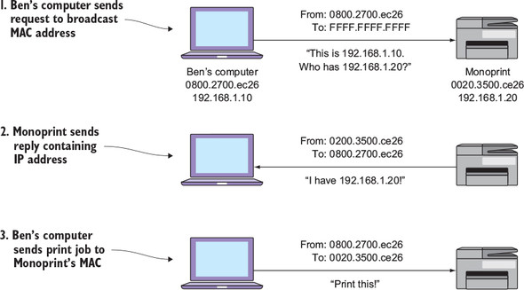
Remember that all network devices must use MAC addresses to communicate. In order for my computer to get the ARP request to all devices on the network, it has to address the Ethernet frame to some MAC address. It can’t send it to a blank address. So it sends the ARP request to the broadcast MAC address. Each device listens for the broadcast address in addition to listening for its own MAC address. This ensures that every device on the network pays attention to every ARP request.
In step 1, my computer sends an ARP request to the broadcast MAC address (FFFF.FFFF.FFFF). In step 2, Monoprint sends back an ARP reply containing its IP address (192.168.1.20). Finally, in step 3, my computer sends the print job to Monoprint’s MAC address.
The switch floods this frame out all ports, including the port Monoprint is connected to. Monoprint receives the frame, peeks inside, and sees the ARP request. Monoprint sees the query “Who has 192.168.1.20?” and thinks, “Oh, that’s my IP address!” Monoprint then sends an ARP reply back to my computer: “This is 192.168.1.20. My MAC address is 0020.3500.CE26.” Bingo. My computer now knows Monoprint’s MAC address and will communicate with it using that.
ARP is the secret sauce that rescues you from having to think about MAC addresses very much. It frees you up to think in terms of friendly, meaningful IP addresses the vast majority of the time.
2.6. Connecting broadcast domains using a router
Now that you’re free to think in terms of IP addresses, it’s time to learn how devices use them to communicate across broadcast domains.
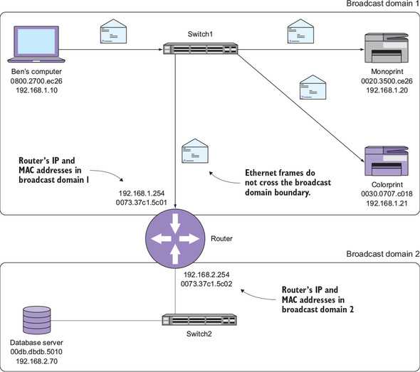
At this point you have two separate broadcast domains with no connectivity between them. In order to join the two broadcast domains together without re-creating a single broadcast domain, you need a special device called a router. A router physically connects broadcast domains in such a way that frames can’t cross the broadcast domain boundary. Because frames are what contain source and destination MAC addresses, the router effectively hides the MAC addresses in one broadcast domain from the MAC addresses in the other.
In figure 2.10, the router physically sits on both broadcast domains. It has at least two ports or interfaces, one to connect to each broadcast domain. Each network interface on a router has its own unique MAC address. Keep in mind that each interface on the router has a unique MAC address only for the purpose of being compatible with the Ethernet standard that all the other devices on the network use. Just like e-books still use “pages,” routers use MAC addresses for backward compatibility. Not only does the router have two MAC addresses, but it also has two IP addresses. On the interface connecting to Switch1, the router has an IP address of 192.168.1.254. On the interface connecting to Switch2, the router has an IP address of 192.168.2.254. Again, these are unique IP addresses, and the third octet (1 or 2) corresponds to the broadcast domain.
Figure 2.10. A router connecting two broadcast domains. The router has a unique IP and MAC address for each broadcast domain. Notice that Ethernet frames do not traverse the broadcast domain boundary.
2.6.1. Where are you? Where am I?
My computer has an IP address of 192.168.1.10 and resides in broadcast domain 1. A database server with an IP address of 192.168.2.70 resides in broadcast domain 2. The significance of these addresses is obvious to a person. Devices with 192.168.1.x addresses are in broadcast domain 1, and those with 192.168.2.x addresses are in broadcast domain 2.
But my computer doesn’t know that. Computers are, after all, just dumb machines that do what we tell them. So my computer needs some way to know which broadcast domain it’s in. Once it knows that, it will be able to figure out whether another device is in the same broadcast domain or a different one.
2.6.2. Understanding subnets
In reality, broadcast domains aren’t given numbers because they’re not real things. But associating a set of IP addresses with a broadcast domain makes the abstract idea of a broadcast domain a lot easier to think about and work with. The set of addresses that corresponds to a broadcast domain is called a subnetwork, or subnet for short.
Take the 192.168.1.x subnet, for example. When you think about it, there’s nothing about this address that says, “All addresses from 192.168.1.1 to 192.168.1.255 are in the same broadcast domain!” Even if you were already thinking that, you probably got that idea from this chapter and not just from looking at the address. But my computer can’t read and comprehend as humans can, so you need a more explicit way of telling it which broadcast domain it’s in.
To do this, you use a subnet mask. The subnet mask is an additional quartet of octets, formatted like an IP address, that indicates which IP addresses are inside the broadcast domain and which are outside.
As you can see in figure 2.11, my computer has an IP address of 192.168.1.10 and a subnet mask of 255.255.255.0. Line the two up as shown in table 2.2 and compare each octet. A 255 in the subnet mask indicates that another IP with the same octet is in the same broadcast domain. A 0 in the subnet mask indicates that the corresponding octet has no bearing on the broadcast domain.
Figure 2.11. Output from ipconfig showing my computer’s IP information

Table 2.2. Determining the broadcast domain based on the IP address and subnet mask
| My computer’s IP address | 192 | 168 | 1 | 10 |
| Subnet mask | 255 | 255 | 255 | 0 |
My computer’s IP address and subnet mask are useless by themselves. The question at hand is whether 192.168.2.70 is in the same broadcast domain as my computer. Let’s plug in that IP address and find out, as shown in table 2.3.
Table 2.3. The database server’s IP address is in a different subnet than my computer’s IP address.
| My computer’s IP address | 192 | 168 | 1 | 10 |
| Subnet mask | 255 | 255 | 255 | 0 |
| Database server’s IP address | 192 | 168 | 2 | 70 |
The first two octets match, but the third octet is different. And because the subnet mask for that octet is 255, my computer knows that the database server is in a different broadcast domain. So in order to get across to the database server, it has to traverse the router. But before it can use the router, it has to know that the router exists and how to reach it.
Open a Windows command shell and type ipconfig. Note the IP address and subnet mask. Think of a different IP address that you know your organization uses. Determine whether it’s in the same broadcast domain as your machine.
2.7. Traversing broadcast domains using a default gateway
Now that my computer has done the hard work of figuring out that the database server is on a different broadcast domain, it needs to know which router to use to connect to the database server. For this, it checks its default gateway address.
My computer has a default gateway address of 192.168.1.254. This corresponds to the IP address of the router’s interface that sits in broadcast domain 1. Based on the default gateway address, my computer knows that when it needs to send anything to an IP address outside its own broadcast domain, it must relay that message through the router.
Note that my computer’s IP address—192.168.1.10—and the default gateway IP address are in the same subnet. This is really important. If a device isn’t on the same broadcast domain and subnet as its router, that device can’t reach any devices outside its broadcast domain.
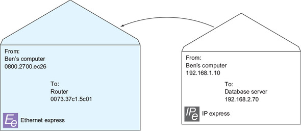
My computer sends an ARP request for 192.168.1.254, and the router responds with its own MAC address of 0073.37c1.5c01. My computer puts together an Ethernet frame addressed to the router’s MAC address. But this time it also puts together a smaller envelope called an IP packet. If an Ethernet frame is a large envelope with MAC addresses, an IP packet is a smaller envelope with source and destination IP addresses.
The IP packet contains my computer’s IP address, 192.168.1.10, as the source and the server’s address, 192.168.2.70, as the destination. Figure 2.12 illustrates my computer stuffing this smaller envelope—the IP packet—into the larger envelope—the Ethernet frame, which, again, has the router’s MAC address as the destination. This process of “stuffing the Ethernet envelope” is called encapsulation.
Figure 2.12. IP packet being encapsulated in an Ethernet frame
My computer sends the Ethernet frame containing the IP packet off to the router. The router receives the Ethernet frame, pulls out the IP packet, and sees the IP packet’s destination—192.168.2.70. The router recognizes that 192.168.2.70 is in the same broadcast domain as the interface connected to broadcast domain 2.
The router then sends an ARP request for the server’s IP address, 192.168.2.70. The ARP request says, “This is 192.168.2.254. Who has 192.168.2.70?” The server responds with its MAC address, and the router takes the IP packet and tucks it inside a new Ethernet frame addressed to the server’s MAC address, as shown in figure 2.13.
Figure 2.13. Router re-encapsulating the IP packet from my computer
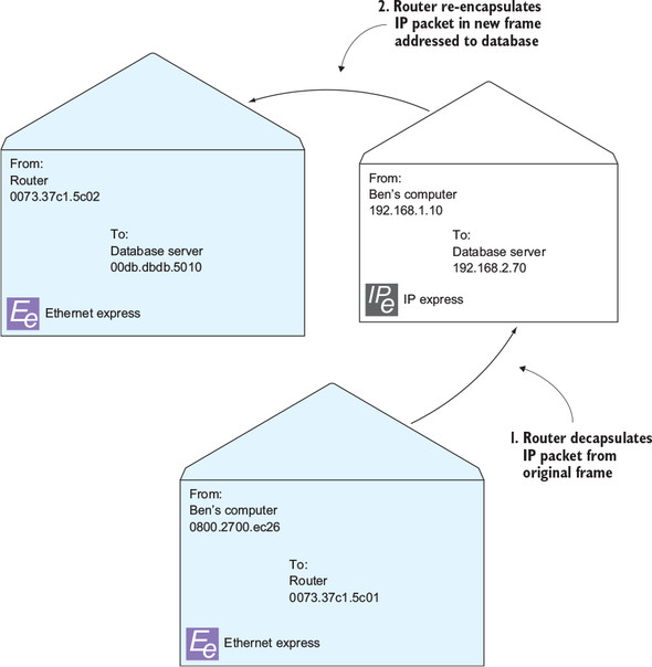
In step 1, the router removes (decapsulates) the IP packet from the original frame. In step 2, the router re-encapsulates the packet in a new frame addressed to the database server.
Notice that the IP packet itself never changes during this process. The router preserves both the source and destination IP addresses but changes only the MAC addresses on the Ethernet frames. The router then sends this new Ethernet frame to the server. The server receives it, takes out the IP packet, and says, “Hey! I’m 192.168.2.70! This packet is meant for me.”
Figure 2.14 illustrates how the router gets the IP packet across the broadcast domain boundary while hiding the MAC addresses in one broadcast domain from the devices in the other. This process is called IP routing.
Figure 2.14. Using a router to traverse broadcast domains

In step 1, my computer sends an ARP request to get the router’s MAC address. In step 2, the router sends an ARP reply containing its IP address. In step 3, my computer sends a frame addressed to the router’s MAC address (0073.37c1.5c01). The frame contains an IP packet addressed to the database server (192.168.2.70). In step 4, the router sends an ARP request to get the database server’s MAC address. In step 5, the database server sends an ARP reply. Finally, in step 6, the router sends a frame addressed to the database server’s MAC address (00db.dbdb.5010) containing the original IP packet.
Now it’s time to put it all together. Figure 2.15 shows how the IP packet from my computer gets all the way to the database server without any unnecessary flooding.
Figure 2.15. Using routing and switching to get an IP packet from one broadcast domain to another without unnecessary flooding

In step 1, my computer encapsulates an IP packet in a frame addressed to the router. It sends the frame to Switch1, which forwards it to Switch2. In step 2, the router removes the IP packet, looks at the destination IP address, and re-encapsulates it in a new frame addressed to the database server. In step 3, the router sends the new frame to Switch2, which forwards it to the database server.
2.8. Managing routers and switches
At this point, you should have a basic understanding of the roles routers and switches play. You’re probably anxious to get your hands on these devices and start poking around and configuring them. But before you can do that, you need to actually get access to them.
Routers have their own IP addresses, but switches can have them too. You’ll typically find a special management IP address assigned to each router and switch on a network. The management IP address allows you to administer these devices remotely without having to physically walk up to the device and plug into the serial console port. Your organization’s routers and switches are likely locked in a closet or data center facility somewhere, and even if you have physical access to them, configuring them in person is a pain. That’s why you need to obtain the management IP addresses and login credentials for each device you might need to administer. Be sure to do this before tomorrow’s lesson.
2.9. Hands-on lab
Download the inventory worksheet from the Source Code link at https://www.manning.com/books/learn-cisco-network-administration-in-a-month-of-lunches. Obtain the management IP addresses of all routers and switches on your network (or lab) and record them. Also obtain the login credentials (usernames and passwords) for logging into each of these devices.
On your computer, open an administrative command prompt or terminal. Get the MAC address, IP address, and default gateway of your computer with ipconfig /all. Type arp –a and get the MAC address of the default gateway. Record this information in the inventory worksheet.