Chapter 13. Optimizing network performance by using port channels
Remember from the last chapter that you have two connections between Switch1 and Switch2, and that the Spanning Tree Protocol (STP) allows traffic to traverse only one of those links. This prevents bridging loops but has a downside: it consumes an additional port on each switch without letting you use the bandwidth of those ports.
A port channel—also known as an EtherChannel—lets you have the best of both worlds. It allows traffic to flow simultaneously across both links while still preventing bridging loops.
As you go through this chapter, you’ll learn how to configure a port channel to achieve the configuration shown in figure 13.1.
Figure 13.1. Port channel between Switch1 and Switch2
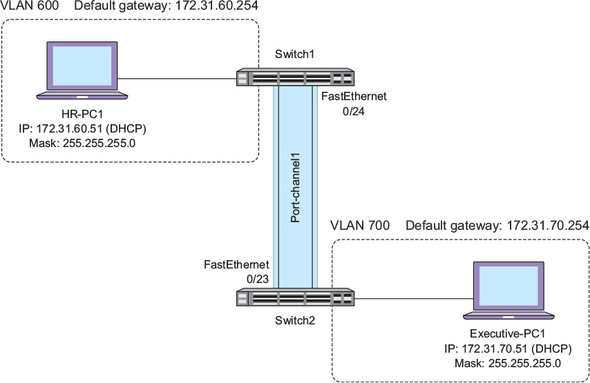
Notice that the port channel consists of FastEthernet0/23 and 0/24 and is called Port-channel1. When you configure a port channel on a switch, the switch creates a logical or virtual interface to represent the port channel.
In keeping with Cisco tradition, a port channel may also be called an Ether-Channel, a bundle, or a port group. I’ll use the term port channel most of the time, but in the configuration commands and output, you’ll see some of these other terms pop up.
As you spend more time learning how to administer Cisco networks, you’ll begin to notice that there are often multiple ways to achieve the same result. Which particular method you use depends not so much on the result you want to achieve but on how long it will take and how scalable it will be. Port channel configuration is no different.
Think back to chapter 10 when you configured VLAN trunks between your switches. The Dynamic Trunking Protocol (DTP), which is enabled by default on Catalyst switches, made it possible for you to set up a trunk by configuring a switch on only one end of the link.
You can’t get away with that with port channels. Unlike VLAN trunks, the only way to get a port channel up and going is to touch both switches.
13.1. Static or dynamic?
Before setting out to configure a port channel, you need to decide how you want to go about it. When it comes to configuring a port channel between Cisco switches, you have two basic options: static or dynamic.
13.1.1. Static
A static port channel is analogous to an unconditional VLAN trunk port. A switch configured with an unconditional trunk port has no regard for how the switch on the other end is configured. In the same way, a static port channel binds two or more physical ports into a single logical port channel interface regardless of what the switch on the other end is doing.
The big downside to this is that it creates a tremendous potential for bridging loops and dropping or “black-holing” traffic. I’ll get into more detail on this later in the chapter, but when you configure a port channel, it hides the physical interfaces from Spanning Tree so that Spanning Tree can no longer place any of the individual interfaces into a blocked state.
The upside to creating a static port channel is that a quick glance at the running configuration makes it abundantly clear that there is a port channel, as well as which physical ports it comprises.
13.1.2. Dynamic
A dynamic port channel is somewhat analogous to negotiating a VLAN trunk using DTP. But there are two big differences.
The first difference is that there isn’t just one protocol that can negotiate a port channel. There are two: the Link Aggregation Control Protocol (LACP) and Cisco’s Port Aggregation Protocol (PAgP). In this chapter, I cover only LACP because it’s the most widely used.
The second difference is that unlike DTP, LACP and PAgP aren’t enabled by default. You still have to touch both switches, and you have to specify which protocol you want to use.
The big advantage of using LACP or PAgP is that they perform sanity-checking to ensure that a port channel will work properly before actually creating it. This is similar to how DTP does its own checking before creating a VLAN trunk. By providing this sanity-checking, these dynamic protocols ensure your port channel won’t black-hole traffic or create bridging loops.
The relatively small disadvantage of the dynamic protocols is that they entail a slight initial delay, which you’ll witness in a moment when you configure a port channel using LACP.
13.2. Configuring a dynamic port channel using the Link Aggregation Control Protocol
Creating a port channel dynamically using the Link Aggregation Control Protocol is the most common method, so you’ll start with that. Using LACP to dynamically form a port channel is so common that in the minds of many, the terms LACP and port channel are synonymous. By understanding the subtle distinction between a port channel and one of the protocols used to negotiate it—LACP—you’ll be well ahead of the pack.
To reiterate, the Link Aggregation Control Protocol is just that—a protocol. You configure it on two switches, and it works to establish a port channel between those switches. Simply configuring LACP doesn’t guarantee that you’ll end up with a working port channel.
On Switch1 and Switch2, issue the following commands:
interface range fa0/23-24
channel-group 1 mode active
The active keyword indicates that you want to use LACP, as opposed to PAgP or a static port channel.
Among a slew of output, you should see this on both switches:
*Mar  2 04:26:38.669: %LINK-3-UPDOWN: Interface Port-channel1, changed state to up
*Mar  2 04:26:39.676: %LINEPROTO-5-UPDOWN: Line protocol on Interface Port-channel1, changed state to up
Notice that the Port-channel1 interface doesn’t come up until you issue the commands on both switches. This is because all you did was configure LACP to try to negotiate a port channel. In order for LACP to do that, you must configure both Switch1 and Switch2 to speak to each other using LACP. Before either switch creates the Port-channel1 interface, both switches must explicitly agree with each other via LACP to form an EtherChannel before either of them actually does it.
Once the port channel comes up, you can verify which specific ports are parts of the EtherChannel.
On Switch1 and Switch2, issue a show etherchannel summary.
You should see this:
Switch2#show etherchannel summary
Flags:  D - down        P - bundled in port-channel
        I - stand-alone s - suspended
        H - Hot-standby (LACP only)
        R - Layer3      S - Layer2
        U - in use      f - failed to allocate aggregator

        M - not in use, minimum links not met
        u - unsuitable for bundling
        w - waiting to be aggregated
        d - default port


Number of channel-groups in use: 1
Number of aggregators:           1

Group  Port-channel  Protocol    Ports
------+-------------+-----------+---------------------
1      Po1(SU)         LACP      Fa0/23(P)   Fa0/24(P)
Notice that the protocol is LACP. Both physical ports, FastEthernet0/23 and 0/24, are part of the bundle.
Another reliable way to verify the presence of a port channel is to check Spanning Tree.
On Switch1 and Switch2, issue a show spanning-tree vlan 700.
The output should differ slightly from what you saw earlier:
Switch2#sh spanning-tree vlan 700

VLAN0700
  Spanning tree enabled protocol rstp
  Root ID    Priority     33468
             Address      0023.ab40.8e00
             Cost         12
             Port         64 (Port-channel1)
             Hello Time   2 sec  Max Age 20 sec  Forward Delay 15 sec

  Bridge ID  Priority     33468  (priority 32768 sys-id-ext 700)
             Address      0024.5088.6d80
             Hello Time   2 sec  Max Age 20 sec  Forward Delay 15 sec
             Aging Time   300 sec

Interface           Role Sts Cost      Prio.Nbr Type
------------------- ---- --- --------- -------- ----
Fa0/21              Desg FWD 19        128.23   P2p Edge
Po1                 Root FWD 12        128.64   P2p
Notice that FastEthernet0/23 and 0/24 don’t show up here. Only Po1—short for Port-channel1—appears. As I said earlier, the port channel hides the physical ports from Spanning Tree.
If this configuration seems ridiculously easy, it’s because it is. LACP does the dirty work of making sure everything is in order before attempting to bring up a port channel. To really appreciate this, it helps to contrast it with a static configuration. But before you can do that, you need to get things back to square one by deleting the existing port channel.
On Switch1 and Switch2, issue the following command to delete the Port-channel1 interface:
no interface port-channel 1
This command might seem a bit strange because it deletes an interface. But remember that Port-channel1 is (or was) a virtual interface. It’s an abstraction of two physical interfaces: FastEthernet0/23 and 0/24.
When you delete the port channel interface, IOS does something that you probably wouldn’t expect. It shuts down those interfaces!
On Switch1 and Switch2, look at the running configuration of FastEthernet0/23 and 0/24:
Show run int fa0/23
Show run int fa0/24
You should see the following:
Switch2#show run int fa0/23
interface FastEthernet0/23
 shutdown
end

Switch2#show run int fa0/24
interface FastEthernet0/24
 shutdown
end
It goes without saying that you’re not going to have a port channel with both member interfaces shut down. To verify that the port channel is truly gone for good, you need to re-enable the physical interfaces.
On Switch1 and Switch2, bring FastEthernet0/23 and 0/24 back up:
Int range fa0/23-24
No shutdown
Verify that the port channel is still gone with a show etherchannel summary.
You should no longer see the port channel:
Switch2#show etherchannel summary
Flags:  D - down        P - bundled in port-channel
        I - stand-alone s - suspended
        H - Hot-standby (LACP only)
        R - Layer3      S - Layer2
        U - in use      f - failed to allocate aggregator

        M - not in use, minimum links not met
        u - unsuitable for bundling
        w - waiting to be aggregated
        d - default port

Number of channel-groups in use: 0
Number of aggregators:           0

Group  Port-channel  Protocol    Ports
------+-------------+-----------+-----
Now that the port channel is completely gone, you’re ready to reconfigure it statically.
13.3. Creating a static port channel
Configuring a static port channel is just as easy as using LACP, but it doesn’t provide you the same sanity checks and protection that LACP does. Given that, you might question why anyone would even dream of creating a static port channel.
Generally, there are two main reasons. First, some organizations don’t like the idea of using dynamic protocols. If possible, they avoid DTP, LACP, and anything else that has the ability to dynamically alter the network without direct human intervention. The second reason is that if you need to create a port channel between a Cisco switch and an older switch that doesn’t support LACP or PAgP, then a static port channel is the only option.
If you want (or have) to go the static route, the EtherChannel Misconfiguration Guard feature provides some protection against bridging loops caused by a misconfigured port channel. It’s enabled by default.
On Switch1 and Switch2, ensure that EtherChannel Misconfiguration Guard is enabled:
spanning-tree etherchannel guard misconfig
Configure a static port channel:
interface range fa0/23-24
channel-group 1 mode on
Verify with a show etherchannel summary.
You should get this familiar output:
Switch2#sh etherchannel summary
Flags:  D - down        P - bundled in port-channel
        I - stand-alone s - suspended
        H - Hot-standby (LACP only)
        R - Layer3      S - Layer2
        U - in use      f - failed to allocate aggregator

        M - not in use, minimum links not met
        u - unsuitable for bundling
        w - waiting to be aggregated
        d - default port

Number of channel-groups in use: 1
Number of aggregators:           1

Group  Port-channel  Protocol    Ports
------+-------------+-----------+---------------------
1      Po1(SU)          -        Fa0/23(P)   Fa0/24(P)
It’s almost identical to what you saw before, but this time the Protocol column is empty because you’re not using LACP or PAgP. The port channel, however, is still up and FastEthernet0/23 and 0/24 are members of it.
This might seem a bit too perfect. After my dire warning about possibly creating bridging loops, so far everything seems to be humming along smoothly. So let’s make things interesting. Let’s break something!
On Switch1 only, delete the port channel:
No interface po1
Remember that when you delete a port channel interface, IOS shuts down the physical member interfaces: FastEthernet0/23 and 0/24. Bring them back up:
Int range fa0/23-24
No shut
On Switch1, you won’t get any output indicating a problem. And on Switch1, nothing obvious will happen at first. But after about a minute, you may see this error indicating a bridging loop:
*Mar 1 00:50:03.809: %SW_MATM-4-MACFLAP_NOTIF: Host 2c27.d737.9ad1 in vlan 700 is flapping between port Fa0/21 and port Po1
Almost another minute later, EtherChannel Misconfiguration Guard will kick in and shut down the port channel:
*Mar 1 00:50:31.265: %PM-4-ERR_DISABLE: channel-misconfig (STP) error detected on Po1, putting Po1 in err-disable state
The channel-misconfig (STP) error detected message indicates that the EtherChannel Misconfiguration Guard feature detected a bridging loop and shut down the port channel interface.
To sharpen the distinction between creating a port channel statically versus using LACP, note that it took about two minutes for EtherChannel Misconfiguration Guard to shut down the port channel. In a live network, this could have resulted in two minutes of downtime or at least very poor network performance. LACP, on the other hand, would have detected the problem and shut down the port channel immediately.
To get the port channel back up, you need to re-create the port channel on Switch1 and get FastEthernet0/23 and 0/24 out of error-disabled state on Switch2.
On Switch1, issue the following configuration commands to re-create the port channel:
interface range fa0/23-24
channel-group 1 mode on
On Switch2, bounce FastEthernet0/23 and 0/24 to get them out of the error-disabled state:
Int po1
Shutdown
No shutdown
You should see the port channel come back up on both switches.
13.4. Load-balancing methods
At the beginning of the chapter, I said that a port channel allows traffic to flow simultaneously across both links. The port channel you just configured will allow traffic to simultaneously traverse FastEthernet0/23 and 0/24. But the way that traffic passes over those links is anything but indiscriminate.
To understand how a port channel decides which individual link to send traffic across, look at figure 13.2.
Figure 13.2. The default port channel load-balancing method sends traffic from Executive-PC1 across the FastEthernet0/23 link.

Notice that I’ve added an additional computer to VLAN 700. Don’t worry about adding another computer to your topology. The purpose here is to just show you how port channels forward traffic.
By default, all port channels forward traffic based on the source MAC address of the frame. Notice that traffic from Executive-PC1—with a source MAC address of 0800.2759.d9fd—goes over FastEthernet0/23. You don’t need to understand the algorithm IOS uses to make this decision, but you should know how to find out which port it will send traffic out of given a particular source MAC address.
On Switch2, issue the following command to determine which physical port traffic from Executive-PC1 (0800.2759.d9fd) would traverse:
test etherchannel load-balance interface port-channel 1 mac 0800.2759.d9fd ffff.ffff.ffff
You should get the following output:
Switch2#test etherchannel load-balance interface port-channel 1 mac 0800.2759.d9fd ffff.ffff.ffff
Would select Fa0/23 of Po1
The output indicates that traffic from Executive-PC1 would egress FastEthernet0/23 every single time. This might seem to defeat the entire purpose of the port channel, which is to allow you to use the bandwidth of both links simultaneously. But on closer inspection, you can see that the port channel does use both links.
On Switch2, issue the following command to determine which physical port traffic from Executive-PC2 (0800.27F8.0651) would traverse:
test etherchannel load-balance interface port-channel 1 mac 0800.27F8.0651 ffff.ffff.ffff
You should see the following output:
Switch2#test etherchannel load-balance interface port-channel 1 mac 0800.27F8.0651 ffff.ffff.ffff
Would select Fa0/24 of Po1
Traffic from Executive-PC2 would traverse the other link, FastEthernet0/24, as shown in figure 13.3.
Figure 13.3. The default port channel load-balancing method sends traffic from Executive-PC2 across the FastEthernet0/24 link.

This is exactly how the port channel uses both links simultaneously: by performing load balancing (or, more accurately, load sharing) based on the source MAC address.
As a general rule, you won’t change the default load-balancing method, even though you can. If you ever run into any unexpected behavior, or if you get unexpected output, you can verify the configured load-balancing method.
On Switch1 and Switch2, verify the current load-balancing method with the following command:
Show etherchannel load-balance
You should see the following:
Switch2#show etherchannel load-balance
EtherChannel Load-Balancing Configuration:
        src-mac

EtherChannel Load-Balancing Addresses Used Per-Protocol:
Non-IP: Source MAC address
  IPv4: Source MAC address
  IPv6: Source MAC address
That lone src-mac in the output is short for “source MAC”—the currently configured load-balancing method. Keep in mind that the methods don’t have to match on both switches. Mismatched load-balancing methods won’t necessarily cause any problems, but they can, depending on the particulars of the network. In the worst case, you wouldn’t be able to utilize the full bandwidth of the port channel, and network performance would suffer.
Again, I want to emphasize that you shouldn’t change the load-balancing method under normal circumstances. But I also recognize that someone else might change it, so you need to know how to change it back to the default.
On Switch1, set the load-balancing method to src-mac:
port-channel load-balance src-mac
That command might take you by surprise because it doesn’t include the keywords etherchannel or channel-group. As usual, rely on the inline help to guide you when you can’t remember the syntax of the command.
13.5. Commands in this chapter
Refer to table 13.1 for a refresher of this chapter’s commands.
Table 13.1. Commands used in this chapter
13.6. Hands-on lab
In this lab, you’ll re-create your port channel one more time using LACP, but this time you’ll add an additional link. Follow these steps to complete the lab.
- Delete the existing port channel on Switch1 and Switch2.
- Connect FastEthernet0/22 on both switches.
- Use LACP to create a port channel consisting of FastEthernet0/22, 0/23, and 0/24.