Chapter 14. Making the network scalable by connecting routers and switches together
Right now, Switch1 routes IP traffic between two subnets: 172.31.60.0/24 in VLAN 600 and 172.31.70.0/24 in VLAN 700. This is a common and perfectly acceptable configuration. But there are times when you’ll want to route inter-VLAN traffic using an additional device: a router.
In one case, you may run into a network that just doesn’t have any routers or layer-3 switches. It’s unlikely that such a network would be using VLANs to begin with, because there wouldn’t already be any way to route between them. Hence, if you walk into an organization that needed VLANs set up, but all they have are some layer-2 switches and a router, then the only way to route traffic between VLANs is to use a router.
This specific use case for a router is becoming less and less common as layer-3 switches become more ubiquitous. But organizations of all sizes use routers heavily for other critical functions, including network connectivity between offices and connecting IP phones to the public switched telephone network (PSTN). That’s why, as a Cisco network administrator, it’s important that you have a clear and correct understanding of how these devices function.
In this chapter, I give you a gentle introduction to connecting and configuring routers to perform inter-VLAN routing. Later in the book, you’ll learn about more advanced topics including routing over a wide area network (WAN) and configuring dynamic routing protocols.
Here are the basic steps you’ll be performing in this chapter:
- Connect the router to Switch1.
- Create a VLAN trunk between Switch1 and Router1.
- Configure Router1 to route between VLANs.
14.1. The router-on-a-stick configuration
In this chapter, you’re going to create what network folks colloquially call a router-on-a-stick configuration. The term router-on-a-stick might sound like a not-so-tasty snack idea from the ash heap of fast-food history. But as you can see in figure 14.1, it’s just a way of describing how you’d physically connect a router to a switch.
Figure 14.1. Router-on-a-stick configuration
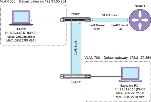
Router1 is physically connected to Switch1 using a single Ethernet connection. This single connection is the stick part of the router-on-a-stick term. Also notice that there’s a VLAN trunk configured between Switch1 and Router1. This trunk is what allows traffic from both VLAN 600 and 700 to reach Router1 so that it can perform inter-VLAN routing.
You may hear someone refer to a physical Ethernet connection between devices as a layer-1 connection, referring to the Physical layer of the Open Systems Interconnect (OSI) model. The VLAN trunk operates at layer 2—the Data Link layer—the same layer where MAC addresses and the Address Resolution Protocol (ARP) function. I’m not going into the fine details of the OSI model in this book, but refer to https://www.manning.com/books/learn-cisco-network-administration-in-a-month-of-lunches for more information.
Recall that Switch1 has two switched virtual interfaces (SVIs): one for VLAN 600 with an IP of 172.31.60.254/24 and another for VLAN 700 with an IP of 172.31.70.254/24. Because Router1 will effectively replace Switch1 as the device that performs inter-VLAN routing between VLANs 600 and 700, you’ll need to remove these SVIs from Switch1.
On Switch1, remove the SVIs for VLANs 600 and 700:
no int vlan 600
no int vlan 700
Removing the SVIs not only removes the virtual interfaces; it also eliminates the corresponding IP addresses from existence. Recall that Executive-PC1 is configured to use 172.31.70.254 as its default gateway, whereas HR-PC1 is configured to use 172.31.60.254 as its default gateway. But as soon as you delete the SVIs for VLANs 600 and 700, those IP address cease to exist. The net effect is that devices in VLANs 600 and 700 can no longer communicate with each other. To remedy this, you’ll connect and configure Router1 to do the job that Switch1 was doing until just now.
14.2. Connecting Router1
You should already have configured Router1 per the lab setup instructions of the online appendix. If you’ve done so, then Router1’s FastEthernet0/0 interface will have an IP address of 192.168.1.201/24. You’ll use this IP address to log into Router1 to configure it in a moment.
Connect Router1’s FastEthernet0/0 port to Switch1’s FastEthernet0/12 port.
Power on Router1.
As you’re waiting for Router1 to boot up, configure FastEthernet0/12 on Switch1 as an 802.1Q trunk port:
Interface f0/12
Switchport trunk encapsulation dot1q
Switchport mode trunk
To reiterate the earlier point, FastEthernet0/12 must be a trunk port so that traffic for VLANs 600 and 700 can traverse the single physical link going to Router1.
Once Router1 has booted up, Telnet to it from Switch1:
telnet 192.168.1.201
Log in using the username “admin” and the password “cisco.”
If you logged in successfully, you should see the Router1# prompt. You might be wondering how you’re able to Telnet to Router1 from Switch1 before configuring the trunk on Router1. The answer lies in the output of the show interfaces fa0/12 trunk command on Switch1:
Switch1#show interfaces fa0/12 trunk

Port        Mode           Encapsulation   Status       Native vlan
Fa0/12      on             802.1q          trunking     1
Notice that the Native vlan is 1. Without getting into the gritty details of 802.1Q encapsulation, this means that Switch1 sends VLAN 1’s traffic out as if FastEthernet0/12 were a normal access port in VLAN 1. To see why this is significant, take a look at the IP address of Switch1’s VLAN 1 SVI:
Switch1#show ip interface Vlan 1 | i Internet
  Internet address is 192.168.1.101/24   192.168.1.101  YES  NVRAM  up   up
It’s in the same subnet as the IP address of Router1’s FastEthernet0/0 interface, which is 192.168.1.201/24. Router1’s interface is effectively just like the network interface on a PC. It’s not trunked and has only one IP address.
On Router1, view the IP information for all interfaces:
show ip interface brief
You should see only one IP address:
Router1#show ip interface brief
Interface         IP-Address      OK? Method Status                 Protocol
FastEthernet0/0   192.168.1.201   YES NVRAM  up                     up
FastEthernet0/1   unassigned      YES NVRAM  administratively down  down
What’s missing here? In order for Router1 to act as the default gateway for the 172.31.60.0/24 (VLAN 600) and 172.31.70.0/24 (VLAN 700) subnets, it needs an IP address in each of these subnets. But you can’t assign three different IP addresses to the FastEthernet0/0 interface. You could use the FastEthernet0/1 interface, but that would consume another port on Switch1. And instead of being a router on a stick, Router1 would be a router on two sticks. The solution is to configure a subinterface on Router1 for each VLAN and subnet.
14.3. Configuring subinterfaces
Conceptually, a subinterface on a router is similar to an SVI on a switch in that it’s a virtual interface that resides in a single VLAN and can have its own IP address. But that’s where the similarities end. Table 14.1 lists the subinterfaces you’ll be configuring on Router1.
Table 14.1. Router1’s (sub)interfaces, IP addresses, and corresponding VLANs
|
IP address |
VLAN |
|
|---|---|---|
| FastEthernet0/0 | 192.168.1.201/24 | 1 |
| FastEthernet0/0.600 | 172.31.60.254/24 | 600 |
| FastEthernet0/0.700 | 172.31.70.254/24 | 700 |
Notice that the subinterfaces share the name of the physical parent interfaces. The name of each subinterface must be the name of the physical parent interface followed by a dot (.) and a unique number between 0 and 4294967295. It’s important to note that the number of the subinterface has no inherent relationship to the VLAN. Instead, you have to specify the VLAN manually within the subinterface configuration.
Create the subinterface FastEthernet0/0.600:
Interface FastEthernet0/0.600
Configure the subinterface to be a member of VLAN 600:
encapsulation dot1Q 600
Assign the IP address 172.31.60.254/24:
ip address 172.31.60.254 255.255.255.0
Add a friendly description:
description VLAN 600 subinterface to Switch1 fa0/12
Verify with a show interface fa0/0.600.
You should see the IP and VLAN information you just configured:
Router1#show int fa0/0.600
FastEthernet0/0.600 is up, line protocol is up
  Hardware is Gt96k FE, address is 0015.fa64.76d2 (bia 0015.fa64.76d2)
  Description: VLAN 600 subinterface to Switch1 fa0/12
  Internet address is 172.31.60.254/24
  MTU 1500 bytes, BW 100000 Kbit, DLY 100 usec,
     reliability 255/255, txload 1/255, rxload 1/255
  Encapsulation 802.1Q Virtual LAN, Vlan ID  600.
  ARP type: ARPA, ARP Timeout 04:00:00
  Last clearing of "show interface" counters never
Notice that the description you added to the configuration shows up as well. The description isn’t necessary for the configuration, but you may find it helpful if you ever forget what the subinterface is for. You can use the description keyword on switch interfaces, too!
Creating a subinterface for VLAN 600 and assigning it an IP address provides a way for devices in VLAN 600 to route IP traffic to different subnets. But in order to perform inter-VLAN routing, Router1 also needs a subinterface in VLAN 700, along with a corresponding IP address for that subnet.
Configure the subinterface for VLAN 700:
interface FastEthernet0/0.700
Encapsulation dot1q 700
Ip address 172.31.70.254 255.255.255.0
Description VLAN 700 subinterface to Switch1 fa0/12
Verify with a show interface fa0/0.700.
You should see the following:
Router1#show int fa0/0.700
FastEthernet0/0.700 is up, line protocol is up
  Hardware is Gt96k FE, address is 0015.fa64.76d2 (bia 0015.fa64.76d2)
  Description: VLAN 700 subinterface to Switch1 fa0/12
  Internet address is 172.31.70.254/24
  MTU 1500 bytes, BW 100000 Kbit, DLY 100 usec,
     reliability 255/255, txload 1/255, rxload 1/255
  Encapsulation 802.1Q Virtual LAN, Vlan ID  700.
  ARP type: ARPA, ARP Timeout 04:00:00
  Last clearing of "show interface" counters never
The next step is to verify that there is, in fact, a VLAN trunk between Router1 and Switch1.
Issue the following commands on Router1 to verify that VLANs 600 and 700 are traversing the FastEthernet0/0 interface:
Show vlans 600
Show vlans 700
This is another area where routers and switches differ quite a bit. Notice that the output looks very unlike what you’d see when doing a show vlan on a switch. Here’s what you should see:
Router1#show vlans 600

Virtual LAN ID:  600 (IEEE 802.1Q Encapsulation)

   vLAN Trunk Interface:   FastEthernet0/0.600


   Protocols Configured:    Address:           Received:     Transmitted:
           IP               172.31.60.254            21                 0
         Other                                        0                 2


Router1#show vlans 700

Virtual LAN ID:  700 (IEEE 802.1Q Encapsulation)

   vLAN Trunk Interface:   FastEthernet0/0.700

   Protocols Configured:    Address:           Received:     Transmitted:
           IP               172.31.70.254           191                64
         Other                                        0                16
I’ve truncated some of the output for brevity, but for each command you should see the VLAN ID, the subinterface name, and the IP address. Don’t worry if you don’t see anything greater than 0 under the Received or Transmitted column. You’ll need to generate some inter-VLAN traffic before those start going up. Recall that in chapter 8 you configured two DHCP scopes on Switch1, as shown in table 14.2.
Table 14.2. DHCP scopes, options, and lease times for each VLAN
|
VLAN |
Subnet |
Mask |
Default gateway |
|---|---|---|---|
| 600 | 172.31.60.0 | 255.255.255.0 | 172.31.60.254 |
| 700 | 172.31.70.0 | 255.255.255.0 | 172.31.70.254 |
You should recognize the default gateway IP addresses for each subnet. They’re the same addresses you just assigned to the subinterfaces on Router1. Hence, you should be able to see that Executive-PC1 is using 172.31.70.254 as its default gateway.
Issue an ipconfig on Executive-PC1.
The IP address may be different, but the default gateway IP should be the same as shown:
PS C:\> ipconfig

Windows IP Configuration


Ethernet adapter Local Area Connection:

   Connection-specific DNS Suffix  . : benpiper.com
   Link-local IPv6 Address . . . . . : fe80::d8ae:58d6:2dc0:9450%11
   IPv4 Address. . . . . . . . . . . : 172.31.70.50
   Subnet Mask . . . . . . . . . . . : 255.255.255.0
   Default Gateway . . . . . . . . . : 172.31.70.254
Although it’s not strictly necessary, you can save yourself some troubleshooting by making sure that you can ping Router1’s FastEthernet0/0.700 interface.
On Executive-PC1, ping 172.31.70.254.
If everything’s configured right, you should get a response:
PS C:\> ping 172.31.70.254

Pinging 172.31.70.254 with 32 bytes of data:
Reply from 172.31.70.254: bytes=32 time=1ms TTL=255
Reply from 172.31.70.254: bytes=32 time=1ms TTL=255
Reply from 172.31.70.254: bytes=32 time=1ms TTL=255
Reply from 172.31.70.254: bytes=32 time=1ms TTL=255
This proves that the VLAN 700 connection between Switch1 and Router1 is working. But the purpose of the router is to perform routing between VLANs 600 and 700. A simple way to verify that inter-VLAN routing works is to ping a host in one VLAN from a host in a different VLAN.
From Executive-PC1, ping HR-PC1 (172.31.60.50).
You should get a reply from HR-PC1:
PS C:\> ping 172.31.60.50

Pinging 172.31.60.50 with 32 bytes of data:
Reply from 172.31.60.50: bytes=32 time=1ms TTL=127
Reply from 172.31.60.50: bytes=32 time=1ms TTL=127
Reply from 172.31.60.50: bytes=32 time=2ms TTL=127
Reply from 172.31.60.50: bytes=32 time=1ms TTL=127
Pinging between hosts in different VLANs isn’t particularly exciting. Even worse, the sheer amount of text-based output you have to look at can make your eyes glaze over, and forget about all the details that are happening under the hood. Figure 14.2 illustrates the details of what happens when you ping HR-PC1 from Executive-PC1.
Figure 14.2. Router1 routing between VLANs 600 and 700
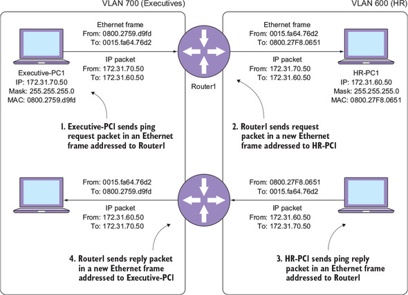
In step 1, Executive-PC1 creates an IP packet with a ping request inside it. It encapsulates that packet inside an Ethernet frame addressed to Router1’s MAC address—0015.fa64.76d2—and sends it out onto VLAN 700. Because Router1’s FastEthernet0/0.700 subinterface is in VLAN 700, it receives the Ethernet frame.
In step 2, Router1 takes the IP packet and stuffs it into a new Ethernet frame addressed to HR-PC1’s MAC address—0800.27f8.0651. It sends this frame out of its FastEthernet0/0.600 interface onto VLAN 600, where HR-PC1 receives it.
In step 3, HR-PC1 creates an IP packet with a ping reply. It encapsulates the packet inside an Ethernet frame addressed to Router1’s MAC address and sends it out onto VLAN 600.
In step 4, Router1 takes the IP packet containing the ping reply and encapsulates it inside a new Ethernet frame addressed to Executive-PC1’s MAC address—0800.2759.d9fd.
That’s a lot of things happening just to route an IP packet between two VLANs! Although figure 14.2 can help you understand the examples in this chapter, in the real world you’re not always going to have such a nice diagram to visually represent how IP traffic flows from one VLAN to another. That’s why it’s important that you be able to quickly determine, based on boring text output, how a router will route traffic.
14.4. The IP routing table
In chapter 7, you briefly looked at the IP routing table on Switch1. Now it’s time to learn how to interpret it.
You should see the following:
Router1#sh ip route
Codes: C - connected, S - static, R - RIP, M - mobile, B - BGP
       D - EIGRP, EX - EIGRP external, O - OSPF, IA - OSPF inter area
       N1 - OSPF NSSA external type 1, N2 - OSPF NSSA external type 2
       E1 - OSPF external type 1, E2 - OSPF external type 2
       i - IS-IS, su - IS-IS summary, L1 - IS-IS level-1, L2 - IS-IS level-2
       ia - IS-IS inter area, * - candidate default, U - per-user static route
       o - ODR, P - periodic downloaded static route

Gateway of last resort is not set

     172.31.0.0/24 is subnetted, 2 subnets
C       172.31.60.0 is directly connected, FastEthernet0/0.600
C       172.31.70.0 is directly connected, FastEthernet0/0.700
C    192.168.1.0/24 is directly connected, FastEthernet0/0
The IP routing table describes each IP subnet the router knows about and which interface it must use to reach that subnet. The information in Router1’s routing table should seem obvious. For example, Router1 knows that it can reach the 172.31.60.0/24 subnet out of the FastEthernet0/0.600 subinterface because the IP address you configured on that subinterface is in the 172.31.60.0/24 subnet. This is called a connected route because Router1 is directly connected to that subnet.
This seems obvious, but what if Router1 receives a packet for a subnet it knows nothing about? For example, if it receives a packet for 1.2.3.4, it has nowhere to send the packet because there’s no corresponding route for it.
On Executive-PC1, ping 1.2.3.4.
You should see a series of unsuccessful pings:
PS C:\> ping 1.2.3.4

Pinging 1.2.3.4 with 32 bytes of data:
Reply from 172.31.70.254: Destination host unreachable.
Reply from 172.31.70.254: Destination host unreachable.
Reply from 172.31.70.254: Destination host unreachable.
Reply from 172.31.70.254: Destination host unreachable.

Ping statistics for 1.2.3.4:
    Packets: Sent = 4, Received = 4, Lost = 0 (0% loss),
When a router receives a packet destined to a subnet for which it has no route, it will send a Destination host unreachable message back to the sender.
So far, you’ve been able to ping HR-PC1 from Executive-PC1. Now it’s time to try a ping in the opposite direction, from HR-PC1 to Executive-PC1.
From HR-PC1, try to ping Executive-PC1.
You should get successful ping replies:
PS C:\> ping 172.31.70.50

Pinging 172.31.70.50 with 32 bytes of data:
Reply from 172.31.70.50: bytes=32 time=1ms TTL=127
Reply from 172.31.70.50: bytes=32 time=1ms TTL=127
Reply from 172.31.70.50: bytes=32 time=2ms TTL=127
Reply from 172.31.70.50: bytes=32 time=1ms TTL=127

Ping statistics for 172.31.70.50:
    Packets: Sent = 4, Received = 4, Lost = 0 (0% loss),
Approximate round trip times in milli-seconds:
    Minimum = 1ms, Maximum = 2ms, Average = 1ms
Recall from chapter 9 that you implemented an ACL to block all IP traffic from the 172.31.60.0/24 subnet to the 172.31.70.0/24 subnet. You had applied that ACL to the VLAN 600 SVI on Switch1, but at the beginning of this chapter you deleted that SVI and assigned its IP (172.31.60.254) to the FastEthernet0/0.600 interface on Router1. The net effect of all this is that HR-PC1 now uses Router1, which has no access list in place. Let’s fix that!
14.5. Applying an ACL to a subinterface
The way you create an ACL and apply it to an interface is almost exactly the same on a router as it is on a switch. You start by creating an ACL to deny all IP traffic from the 172.31.60.0/24 subnet to the 172.31.70.0/24 subnet.
On Router1, create ACL 100 by issuing the following commands:
access-list 100 deny ip 172.31.60.0 0.0.0.255 172.31.70.0 0.0.0.255
access-list 100 permit ip any any
Apply ACL 100 to the FastEthernet0/0.600 subinterface:
int fa0/0.600
ip access-group 100 in
Verify with a show access-list.
Extended IP access list 100
    10 deny ip 172.31.60.0 0.0.0.255 172.31.70.0 0.0.0.255
    20 permit ip any any (23 matches)
Now that you’ve applied the ACL, you shouldn’t be able to ping Executive-PC1 from HR-PC1 anymore.
On HR-PC1, try to ping Executive-PC1 again.
You should see the following:
PS C:\> ping 172.31.70.50

Pinging 172.31.70.50 with 32 bytes of data:
Reply from 172.31.60.254: Destination net unreachable.
Reply from 172.31.60.254: Destination net unreachable.
Reply from 172.31.60.254: Destination net unreachable.
Reply from 172.31.60.254: Destination net unreachable.
Notice that the Destination unreachable message looks similar to the earlier message you got when trying to ping the 1.2.3.4 address. This error is the router’s way of saying that it can’t—or in this case, won’t—send the IP packet along to its destination.
You don’t need to become an expert at deciphering these error messages. Just remember that when you see one, it could indicate a missing route in the IP routing table or an access list blocking traffic.
14.6. Commands in this chapter
Refer to table 14.3 for a list of all the commands used in this chapter.
Table 14.3. Commands used in this chapter
|
Command |
Configuration mode |
Description |
|---|---|---|
| interface fastethernet0/0.600 | Global | Creates the FastEthernet0/0.600 subinterface under the FastEthernet0/0 physical interface |
| encapsulation dot1Q 600 | Interface | Places the selected subinterface in VLAN 600 |
| ip address 172.31.70.254 255.255.255.0 | Interface | Assigns 172.31.70.254/24 to the selected interface |
| show vlans 600 | Global | Displays interfaces in VLAN 600 and their corresponding IP addresses |
| show ip route | Global | Displays the IP routing table |
14.7. Hands-on lab
For today’s lab, you’re going to practice creating and applying ACLs on a router:
- Create a new ACL to prevent devices in the Executives subnet from reaching the HR subnet.
- Apply the ACL to the FastEthernet0/0.700 subinterface.
- Try to ping HR-PC1 from Executive-PC1.
- Remove the ACL from the FastEthernet0/0.700 interface.
- Save your configuration.