PROJECT 1
Light-Up Greeting Card
Get crafty with electricity by designing and making your own light-up greeting card
 Tools
Tools
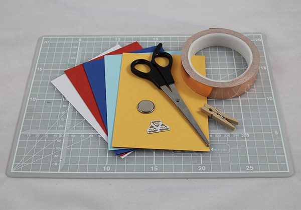
 Sharp scissors
 Ruler, ideally metal
Materials
 Card
Card
 Paper
Paper
 Glue
Glue
 Copper tape
 Two Chibitronics LED stickers
 3V battery
 Wooden clothespin or small bulldog clip
Lots of people love receiving cards, and getting a homemade card feels even better. Taking the time to design and make a card shows that you really care about someone.
In this project, we’ll be taking our first steps in DIY electronics. You’ll make your first paper circuit, and you’ll design and make your first unique project. By using your new electronics skills to add electricity and light to your greeting card, you can really blow your friends’ and family’s minds.
Let’s make!
Choosing Your Materials
Start thinking about what you want your finished greeting card to look like. Before you dive into design, think about who you want to give it to. What occasion will it mark? You could choose to make one for Mother’s Day, Christmas, Hanukkah, or your best friend’s birthday.
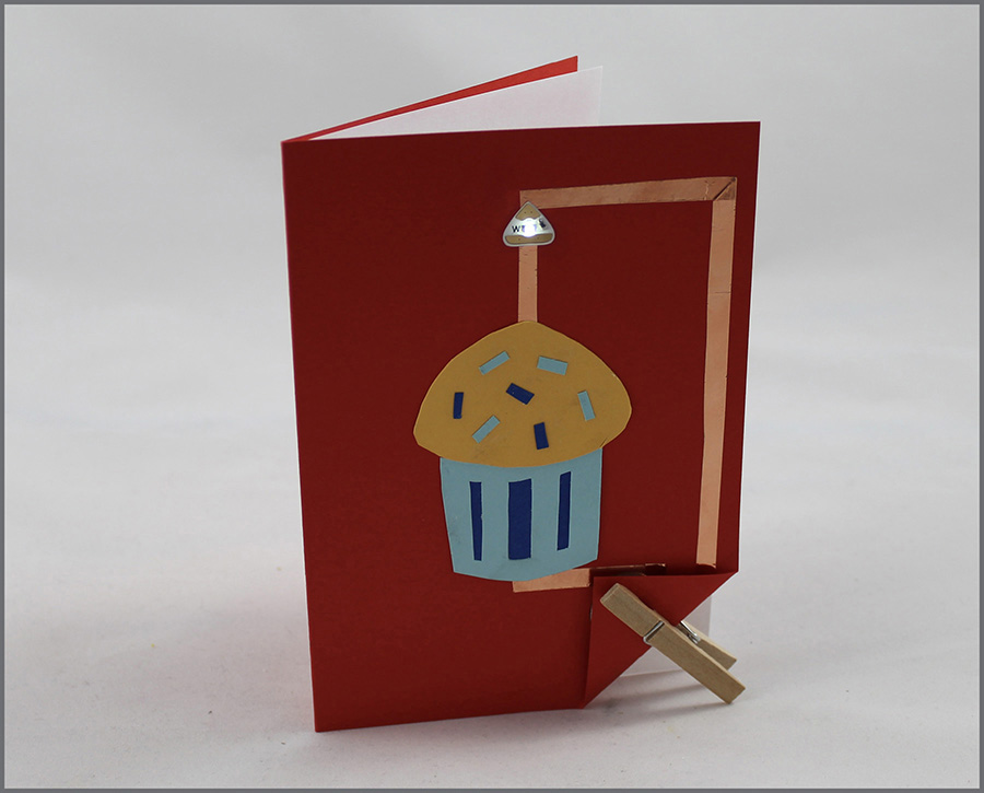
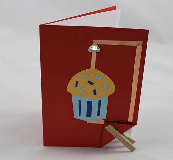
Once you’ve decided who and what your card is for, you can start to come up with ideas for the design. I’ve made a birthday card for my friend Adam. He loves cupcakes, so I want to make him a cupcake-inspired card with a candle that lights up. I’ve chosen a bright blue card that will contrast nicely with the copper tape.
Once you’ve thought about the way you want your card to look, prepare your materials. Make sure that you’ve read the “Paper Circuits: Essential Skills” on pages 4–6 before going any further.
Starting Your First Circuit
Before you start thinking about how you’re going to design your card’s circuit, we are going to build a simple practice circuit on a piece of paper. We’ll be using three components: copper tape, a Chibitronics LED sticker, and a 3V battery.
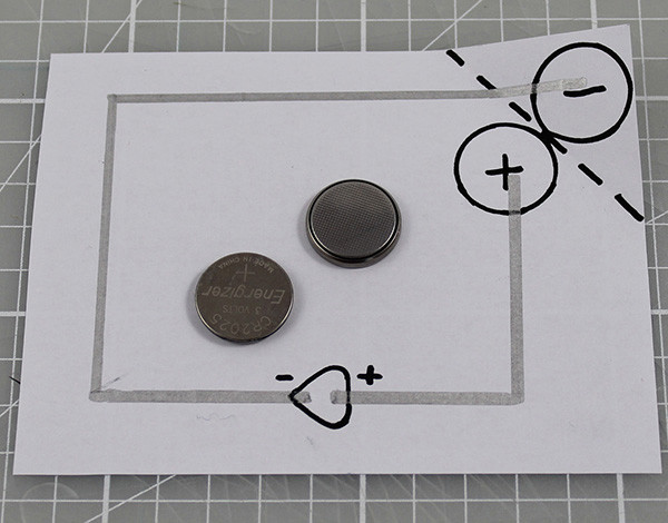
Copper tape is conductive, which means that it can be used to make a path for electricity. We’ll be using it to carry the electricity around the circuit from the battery to the Chibitronics LED sticker and back.
Our 3V battery is the source of power we need to make our circuit work. Take a look at your 3V battery. Flip it over, and you should be able to see that one side of the battery has writing on it, including a + symbol. This is the positive side of the battery. The other side is usually bumpy. This is the negative side of the battery. We need to connect our circuit to both the positive and the negative sides of the battery.
On a piece of paper, trace the template circuit on page 247. This is the layout of your first circuit. The dotted corner should be at the edge of your paper because we’ll be folding it along the dots to make contact with the positive and negative sides of the 3V battery. The triangle-shaped space is for your Chibitronics LED sticker.
 What Is an LED Sticker?
Take a closer look at your LED sticker. On the top of each sticker you can see a tiny yellow bump. This bump is an LED, short for light-emitting diode. An LED is like a tiny light bulb. If you put this LED sticker into a circuit correctly, it will light up!
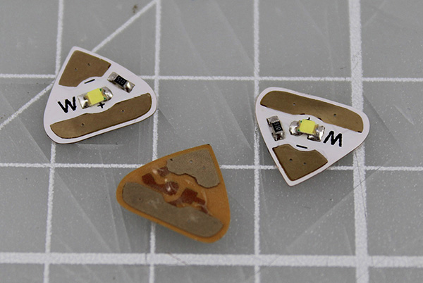
You will also see two shiny strips on your sticker. The long thin strip is positive, and the short, pointed strip is negative. If you look carefully, you’ll be able to see the + and – symbols. You will need to match these symbols up with your battery’s positive and negative sides to make your circuit light up.
These awesome stickers were designed by Jie Qi of Chibitronics, an engineer who loves to craft with paper. Chibitronics has made some great videos to help you use copper tape and LED stickers. Search on YouTube for “getting started with copper tape for paper electronics” to find a great starter guide with lots of tips and tricks.
 How to Work with Copper Tape
Peel the backing off your copper tape, and stick the tape down where the path should go, making sure to leave gaps in the tape where your components will sit. Remove the backing bit by bit to keep the length of tape from sticking to itself.
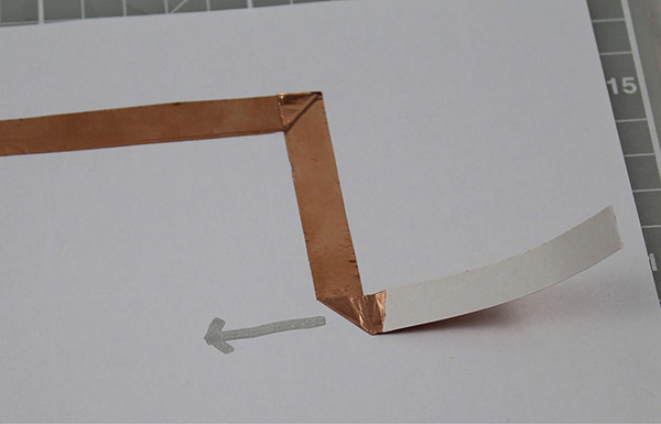
Try to use one continuous piece of copper tape between components. This will give you the most reliable connection. If you run out of tape before finishing your circuit, you can connect two bits of tape together.
If you need to connect two bits of copper tape, don’t just stick one bit on top of the other. Even if your glue is conductive, this can make an unreliable connection, meaning that your LED might flicker or not work at all. Instead, fold under about half an inch at the end of the new bit of tape so that it sticks to itself. Put this bit of tape over the old bit of tape, and then stick it firmly in place with regular sticky tape.
To turn a corner, turn your tape over in the opposite way to the path you want to take, just as in the picture (on the previous page). The sticky side of your tape should be face up. Carefully flatten the turn. Next, turn the tape back over in the direction that you want it to go. Carefully flatten the corner again, and off you go! Corners can be tricky at first. Practice until you get the hang of it.
Laying Down Your Paths
Cut off a piece of copper tape about 8 inches long. Using your traced pattern as a guide, peel back one of the edges of the backing of your copper tape, and start sticking it down along your positive path. Remove the backing bit by bit.
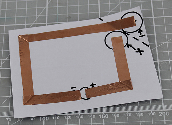
When you get to the first corner, carefully pull the tape over on itself so that it is sticky side up and pointing in the opposite direction to the path. Flatten the turn, and then pull the tape in the other direction so that the sticky side is down and your tape is pointing in the direction of the path. Flatten this turn too, and then keep sticking your tape to your path until you get to the space for the LED sticker.
Tear your copper tape so that it ends in the space for the LED sticker. Then repeat the process for the negative side of your circuit. Make sure that the positive and negative bits of copper tape are inside the space for the sticker but not touching each other; otherwise, your circuit won’t work.
Finishing Your First Circuit
Crease the corner of the paper along the dotted line, and place the battery negative (–) side up over the positive (+) circle. Fold the corner flap over, and clip the battery in place with a wooden clothespin or a bulldog clip.
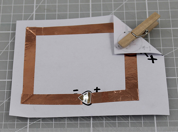
Make sure the positive and negative paths made of copper tape are not touching each other. Then stick the LED circuit sticker on top of the copper tape over the triangular space. Pay attention to the way in which you stick your sticker. The positive side of the LED sticker should connect to the positive side of the battery, and the negative side of the LED sticker should connect to the negative side of the battery.
When your sticker is in place, it should light up. Success? Give yourself a round of applause because you have just built your first paper circuit.
Not working yet? Skip to the end of this project for my troubleshooting guide.
 Adding in More than One LED
Making one LED sticker light up is awesome, but what if you want to make a design with more than one LED?
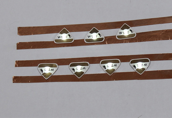
When you design a project with more than one LED, there are two ways to do it. The first way is to connect your LEDs in series, and the second is to connect them in parallel. We’ll use both types of circuits later in this book, but for now, please read the following sections for an introduction.
Each LED sticker takes a certain amount of power from the battery, so if you want to add more than one sticker, you’ll have to know more about how to balance power in your circuit.
It may be tempting to design a circuit with a whole pack of shiny LED stickers, but for your first project you should stick to designing a project with one sticker. By the end of the “Paper Circuits” part of this book, you’ll be a pro at using several components!
 Introducing Series Circuits
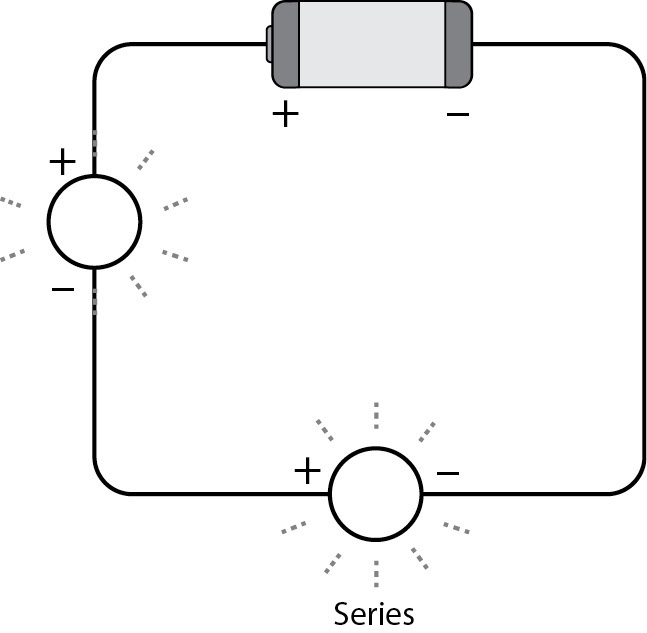
LEDs connected in series are connected end to end, meaning that the negative bit of the first LED connects to the positive bit of the second LED, the negative bit of the second LED connects to the positive bit of the third LED, and so on.
This whole daisy chain of LEDs should be connected up as usual to your power supply: negative to negative and positive to positive. In a series circuit, if one component is faulty, no part of the circuit will work.
The diagram shows a simple series circuit.
 Introducing Parallel Circuits
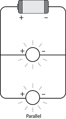
Another way we can make a project with more than one LED is to connect them in a parallel circuit. LEDs connected in a parallel circuit use one path to connect all the positive bits of the LEDs to the positive bit of the battery and another path to connect all the negative bits of the LEDs to the negative bit of the battery.
In a parallel circuit, if one component is faulty, the other parts of the circuit will still work. A circuit with two LEDs and one battery connected in parallel will make your LEDs shine more brightly than the same circuit connected in series, but it will also drain your batteries more quickly.
The diagram shows a simple parallel circuit.
Designing the Circuit for Your Greeting Card
Now that you know the fundamentals of paper circuitry, you can get start by creating your own greeting card design.
Sketch out some ideas for your design, starting with the circuit. Keep it simple to start with, using just one sticker and keeping corners to a minimum.
Clearly mark up your negative and positive paths and how they will connect to your battery. I’d suggest putting the battery in the bottom corner of the front of the card, but you could take the paths round to the back of the card if you’d prefer to hide your battery.
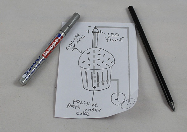
Think about how the rest of your design will work with your circuit. My design uses one LED as the flame on a birthday candle, but you could make a star on top of a tree, a light in the middle of a flower, or a glowing heart. Use your imagination. What can you light up?
You can also choose to cover your LED sticker with some thin paper so that the LED shines through, creating a pretty illumination effect. Don’t do this with card or your LED won’t show through.
Making the Circuit for Your Greeting Card
Cut off a piece of copper tape long enough to reach the first LED sticker. Using your design as a guide, peel back one of the edges of the backing of your copper tape and start sticking it down along your positive path. Remove the backing bit by bit to keep your length of tape from sticking to itself.
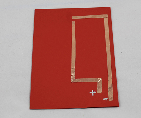
When you get to a corner, pull the tape in the opposite direction to the path. Flatten the turn, and then pull the tape in the right direction. Flatten this turn too, and then keep sticking your tape to your path until you get to the space where the LED should go.
Tear your copper tape so that it ends in the space for your LED sticker. Then repeat this process for the all other parts of your circuit. Make sure that the positive and negative bits of the copper tape are not touching each other; otherwise, your circuit won’t work.
Finishing the Circuit for Your Greeting Card
Crease the corner of the card where your battery goes, and place the battery in the corner flap so that the positive side of the battery is connecting to the positive path and the negative side of the battery is connecting to the negative path. Clip the battery in place with a wooden clothespin or a bulldog clip. If you position your clothespin or clip at a right angle, it will help your greeting card stand upright.
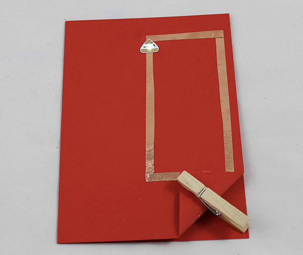
Make sure the positive and negative paths are not touching each other. Then stick the LED sticker on top of the copper tape. Pay attention to the way in which you stick your sticker. The positive side of the LED sticker should connect to the positive side of the battery, and the negative side of the LED sticker should connect to the negative side of the battery.
Does it light up? Awesome! You have just made your first unique paper circuit. Is your circuit not working yet? Skip to the end of this project for my troubleshooting guide.
Finishing the Design for Your Greeting Card
The last thing you need to do is add the rest of your greeting card design around the circuit. As you’re adding in your design, be careful not to rip your copper tape circuit.
One finishing touch that makes a greeting card look extra special is to cut a sheet of thin white paper so that it is slightly smaller than the size of your card. You can fold this paper in half and then glue it inside the card along the internal back edge. You can use this paper to write a personal message to the person for whom you made the card.
 Fix It
Not working? Don’t worry! Follow these steps to figure out why, and fix it.
1. Check your power.
 Is your battery the right way around? Flip it over and see what happens.
 Has it run out of juice? Try another battery.
 Is your battery connecting to your circuit? Make sure that both the negative path and the positive path are connected to the correct side of the battery.
2. Check your components.
 Is your Chibitronics LED sticker the right way around? Remember that the positive side of the battery should be connected to the positive bit of your LED, and the negative side of the battery should be connected to the negative bit of your LED.
 Is your LED securely stuck in place? Loose connections mean that your circuit won’t work.
 Is your sticker on top of an unbroken bit of copper tape? Electricity likes to take the easiest route possible, so if you put an LED sticker on top of an unbroken bit of copper tape, the electricity will go through the copper tape instead of the sticker.
3. Check your wiring.
 Do your positive and negative paths touch? If they are touching, no matter how slightly, your circuit won’t work.
 Are all your paths complete? If your copper tape path has rips or tears in it, electricity may not be able to get through.
 Have you made your path by sticking one bit of copper tape on top of another? Even if your glue is conductive, this can lead to unreliable connections, meaning that your LED might flicker or not work at all.