Certain terrains would always make canal construction difficult, if not impossible. The inclined plane method of overcoming sudden changes in level has already been discussed. This came in various forms, from the simple tub-boat canals, which were often self-acting, with the heavier downward load raising the empty tubs on a parallel track, to the more sophisticated versions worked by steam engines. The most dramatic use of inclined planes was on the Morris Canal. The canal had its origins in a sound commercial idea – to link the industrial region round Pittsburgh with New York. The distance between Pittsburgh and Newark Bay was about 55 miles, but the direct route was impossible, and a more roundabout line had to be taken that meant the finished canal was 102 miles long. Even then there were formidable obstacles. To cross the hills around Lake Hopatcong involved a 914ft climb up one side and a 760ft drop on the other. The Morris Canal and Banking Company was formed with the idea of selling stock worth $2 million – in the event work started in 1829 with just a million in the kitty and no clear plan how to cross the mountains.

The photograph shows inclined plane Number 9, one of twenty-three similar inclines on the Morris Canal in America. Boats are lifted by means of a water turbine controlled from the tower that can be seen at the top of the slope. (Canal Society of New Jersey)
The solution was proposed by Professor James Renwick of Columbia University. His plan was to use just twenty-three locks and twenty-three planes. The latter were very sophisticated. Each incline had a power house at the top. Beneath it was a reaction turbine, set into a well. When a boat needed to be moved the operator opened a valve, and water from the upper level rushed down the well to work the turbine. This connected with a drum, round which a cable was wound that was attached to a cradle on the plane. The boats themselves were flat-bottomed and easily floated on and off the cradle. It was recorded that a barge, loaded with 70 tonnes of coal, could be raised for a vertical distance of 100ft in just a quarter of an hour. Given that to cover this vertical distance would probably have required a dozen locks to be built, the expense of building the incline and power house looks like a sound investment. And using one incline instead of a string of locks was an immense saving in journey time. It was a triumph and by 1860 it was carrying more than 700,000 tonnes of coal and pig iron a year. Unlike most other American canals, however, it was never used for passengers. It remains one of the engineering triumphs of the American canal age.
An alternative to the inclined plane was a vertical lift. One early attempt at getting up a steep rise without an incline was on the Somerset Coal Canal. The canal was built to bring coal from the mines at Poulton and Radstock to the Kennet & Avon at Dundas. The biggest problem was the steep hill at Combe Hay. The engineer Robert Weldon devised the ingenious caisson lock. Although nominally a lock, it was more like a large well. The caisson was a metal box, with watertight doors at either end. Boats could enter the caisson through a short tunnel, after which air was pumped into the box, which floated up to the top of the lock, guided by rails in the side of the well. The doors at the far end could then be opened and the boats could continue on their way. It was not a success and was soon replaced by an inclined plane, and that in turn was removed and a conventional flight of locks was built. The canal has long since been abandoned, but traces of the locks remain, with iron gates. The site of the unique lock is identified by being close to the building still known as Caisson House, but although excavations have revealed just where it was situated, no details have survived to give any clearer indication of exactly how it was built. One can only assume, as the entrance was through a tunnel, that the boatman had to steer his vessel into the caisson. Being shut into a floating box must have been like being enclosed in a miniature submarine.
A more satisfactory form of vertical lock was developed for the Grand Western canal. This venture began optimistically but staggered to a conclusion of sorts, rarely repaying the effort needed to finance and build it. The original scheme was for a canal that would link Exeter to Bristol, as part of a through route for 50 tonne barges all the way to London. The first bad decision was not to start at Exeter at all, but at Tiverton, simply because of the possibility of quick profits carrying stone from local quarries. The engineer was John Rennie and work got under way in 1809, a mere thirteen years after the first proposal. It was to be a contour canal, threading its way through a hilly landscape on a route that involved one colossal U-bend and a section cut into a hillside. Three years later, the canal had reached Holcombe Regis, just 11 miles from Tiverton but having already cost more than the amount estimated for the whole canal. Everything now stopped, and although the canal did have traffic in stone, the revenue never amounted to £1,000 in any one year; not much of a return for an investment of a quarter of a million pounds.
Nothing now happened until the opening of the Bridgwater & Taunton Canal in 1827. It offered the possibility of making a useful connection for the first time for the Grand Western, and the work of extending the latter to Exeter went to a local engineer, James Green. His plans were radical. There would be no conventional locks, just one inclined plane and a series of seven vertical lifts.
The incline plane would work on the hydraulic principle. The weight of the boat going up the plane would be counterbalanced by a large bucket of water falling in a shaft, the bucket being emptied for a boat going in the opposite direction. It was not a success, and a steam engine had to be installed to take over the work. The idea of vertical lifts was not entirely new. But Green’s were the first put into use on a working canal. They worked on a counterbalance system. Boats could be floated into one or other of a pair of caissons, linked by chains. When one caisson was at the top of the lift, the other would be at the bottom. By adding water to the upper caisson it fell, its descent controlled by a brake, while the other one rose. The system worked, and although the canal has long since closed, remains of these unique lifts can still be found.

The Anderton lift was built to move boats between the River Weaver and the Trent & Mersey Canal at the higher level. Built in the nineteenth century it was originally powered by means of a hydraulic ram and two counterbalanced caissons, but was converted to electric power in 1902. The caissons are now separately counterbalanced so can be moved individually. (Mike Peel)

This photograph, probably taken in the 1950s, shows two working boats floating in one of the caissons on the Anderton lift. Each caisson is 75ft long and 15ft deep, designed either to take one barge off the Weaver Navigation or a pair of narrow boats from the Trent & Mersey. (Anthony Burton)
The idea was not followed through with great enthusiasm by other engineers until 1875. Edward Leader Williams, the engineer in charge of improvements to the Weaver Navigation, designed a lift to link it to the Trent & Mersey Canal, 50ft above the river. The lift contained a pair of caissons, each 75ft long, 15ft wide and 5ft deep, weighing 250 tonnes and capable of taking the flats that were in use on the Weaver or the narrow boats of the canal. Set within a massive iron frame, they were originally designed to be counterbalanced and moved by hydraulic rams. The approach from the Trent & Mersey was via a short aqueduct that could be closed off with timber gates with watertight seals. Unfortunately the water used for the rams came from the polluted canal, which damaged the sealants. In 1902, the hydraulic system was replaced by electric motors, and the lift still in use today no longer relies on each caisson counterbalancing the other. Instead, a system of weights hung round the frame in seemingly haphazard fashion do the job, and each caisson moves independently. Lifts of this type, many on a much larger scale, were built and remain in use in North America, Canada and mainland Europe, culminating in the lift at Strépy-Thieu on the Canal du Centre, Belgium. Completed in 2002, it can raise 1,350 tonne barges to a height of 73m. It is still the mightiest lift of its kind, but is due to be overtaken by a new lift in China. The prize for the most unusual boat lift must, however, go to Scotland and the Falkirk Wheel, completed in 2002. Built to reunite the Forth & Clyde and Union Canals, the balanced caissons follow a circular path round giant concrete hoops. When one caisson is aligned with an aqueduct that reaches the wheel at the Union Canal at the upper level, the other is at the level of the Forth & Clyde below.

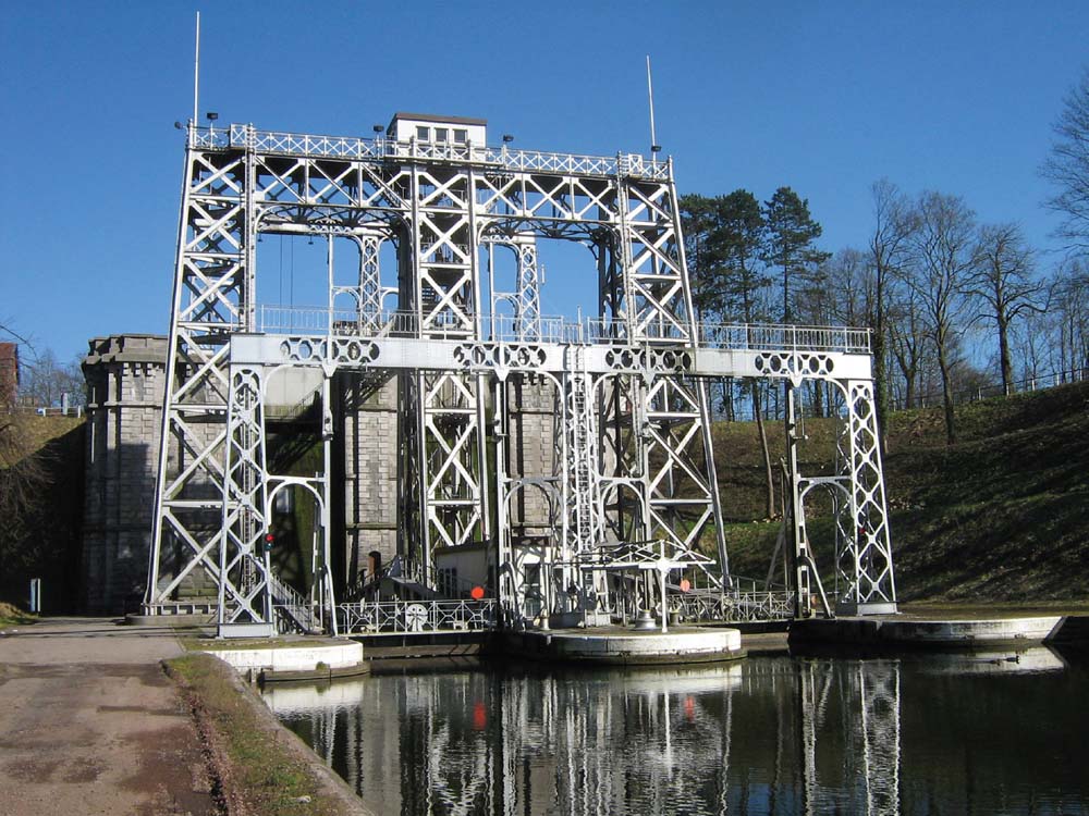
Starting in 1888, an imposing set of four lifts was built for the Canal du Centre in Belgium. Together with two locks they covered a rise of 70m. Although no longer in use, they have been preserved as historic monuments and have been given UNESCO World Heritage status. The photograph shows lift number 3. (Tenger)

The four lifts on the Canal du Centre were replaced in 2002 by this immense lift at Strépy-Thieu. Where the old lifts could only take barges up to 300 tonnes, the new version takes 1,350 tonne barges the full 70m in a single lift. The caissons are counterbalanced: one can be seen at the top of the lift at the right-hand side; the other is at the bottom on the left. (Raymond Speleking)
But there were limits to what even the most ambitious lifts and planes could achieve. Throughout the canal age, waterways were by far the most efficient way of moving goods and if the terrain made it impossible for a canal to reach a particular industrial site then other ways had to be found to bring cargo to canal or river. The answer was to use railed tracks, known as tramways.
The earliest version was developed in Germany. The classic account of mining and metal working, De Re Metallica (1556) by Agricola, shows a mine in which carts run along a fixed wooden track. They are kept on the track by means of pins sticking out from the bottom of the trucks that run in a groove in the centre of the planks. The system became more sophisticated when parallel wooden rails were laid and trucks were given flanged wooden wheels. Tramways became part of the mining scene in many parts of Europe, with many variations. In some systems plain wheels ran inside the rails, but by the eighteenth century the advances in iron production saw a more hardwearing type of tramway come into use. Rails were made of cast iron, generally with an L-shaped cross section to hold the wheels in place. A large network developed in mining areas, especially the north east of England. As the collieries were higher up than the river, all the loads went downhill. The man in charge controlled the descent by means of a handbrake and the horse trotted along behind. Then the horse was harnessed to the cart for the return journey with the empty waggon.

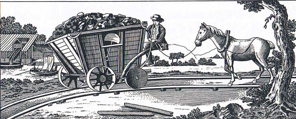
Among the earliest tramways built in Britain were those connecting the collieries of Northumberland to the River Tyne. The illustration shows a typical wagonload of coal running downhill towards the river, controlled by the driver using the crude curved handbrake. The horse, trotting along behind, will be needed for the uphill return journey. It would appear that the rails are L-shaped, with vertical flanges inside the wheels. The tramway ends at Staithes like those seen on the opposite bank, where the coal is being dropped down a chute into a barge. (Anthony Burton)

A tramway, designed by Benjamin Outram, brought coal from Denby to the Derby Canal and survived in use long enough to be photographed. The wagon design has changed very little from that shown in the early drawing, but there is one significant change. The coal was actually carried in boxes, designed to fit snugly into the hold of the narrow boat – an early example of containerisation. (Waterways Archive Gloucester)
In Britain, the tramways became an integral part of some canal systems. A good example is the Brecon & Abergavenny Canal in South Wales. The name is misleading, as it never actually goes to Abergavenny; instead it begins with an end-on meeting with the Monmouthshire Canal at Pontymoile. The Monmouthshire Canal makes economic sense, serving an industrial area of mines and foundries and connecting them to coastal traffic at Newport. The Brecon & Abergavenny, however, sets off on a wandering track, high up a hillside on the edge of the Brecon Beacons, and scarcely touches town or village until it reaches the terminus at Brecon. But the surrounding hills were full of busy industries, from stone quarries to ironworks, and fourteen different tramways were built to create profitable traffic for the canal.
The remains of many of these tramways can still be traced from the canal, often revealed by the sleepers – tell-tale parallel rows of stone blocks with holes in the centre. We are used to seeing railways with sleepers stretching across and under both tracks, but the tramways were worked by horses, which would constantly have been tripping over them. So wooden plugs were inserted in the holes and the rails spiked to the stones, leaving a clear track in between. The most interesting tramway was built by the Hill family, who owned extensive ironworks at Blaenavon, some 4 miles from the canal in a direct line, but separated from it by steep hills. Much of the route can still be followed, and it shows just how important the connection was, as well as the engineering solutions, to make the whole system work.

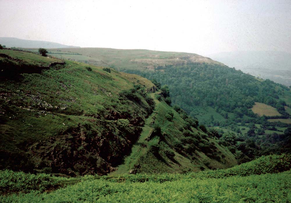
The Brecon & Abergavenny Canal was served by a complex system of tramways, some stretching many miles away from the canal. Thomas Hill established the Blaenavon ironworks (see p.00) in 1789 and built a tramway from the works to the canal with a branch running off to stone quarries. Although the tracks have long since gone, this section can still be clearly seen high up on the hill, Blorenge, as a flat track hugging the contours. (Anthony Burton)
The ironworks were established at Blaenavon in 1789 and work on the canal began four years later. The Hills immediately pressed the canal company to complete the works to Pontymoile so that they could send out their iron. By 1795 they began developing the tramway that would lead from the works to Llanfoist on the canal, with a continuation down to the main road further down the hill. Llanfoist is a spot full of interest. The tramway was carried over the canal on a flat-topped bridge, before continuing down what is now a roadway. Access to the extensive wharf area by road is via a tunnel under the canal. There are two notable buildings on the site. The first is a warehouse on two levels. At the upper level, grooves in the floor suggest the trucks were run straight in. Boats floated right into the lower level for loading. Next to it is Canal House, with little windows on the top floor, looking down both at the wharf and up the hillside at a track that marks the line of the tramway. Walking up the track reveals the typical stone blocks, and halfway up is a platform, above which the track continues on a different alignment. There would originally have been a winding drum here. These are the two inclines that between them took the line through a total vertical of 550ft. The line now emerges on a bracken-covered hillside, and follows the natural contours to a point known as The Tumble, where it goes through a dramatic U-bend. Here one branch leads off to limestone quarries, and the main line disappears into a tunnel, only to emerge again at the ironworks. These are remarkably well preserved, with imposing blast furnaces, and a big tower structure in the centre. This was the water-balance lift, working much like a vertical canal lift, to move trucks and material between the top and bottom of the site.
Travelling the Brecon & Abergavenny Canal today is a joy thanks to its rural quiet and magnificent scenery, and Llanfoist is as peaceful as anywhere. Only the tramway remains hint at what it must once have been like, with the different wharfs filled with stone and iron and the peace disturbed by the rattle of chains and the clatter of wheels as the trucks were hoisted up and down the inclines. The system did not always work perfectly. The Duke of Rutland gave this account of a harrowing experience on one of the Brecon & Abergavenny tramways in his book, Journal of a Tour through North and South Wales, 1805:

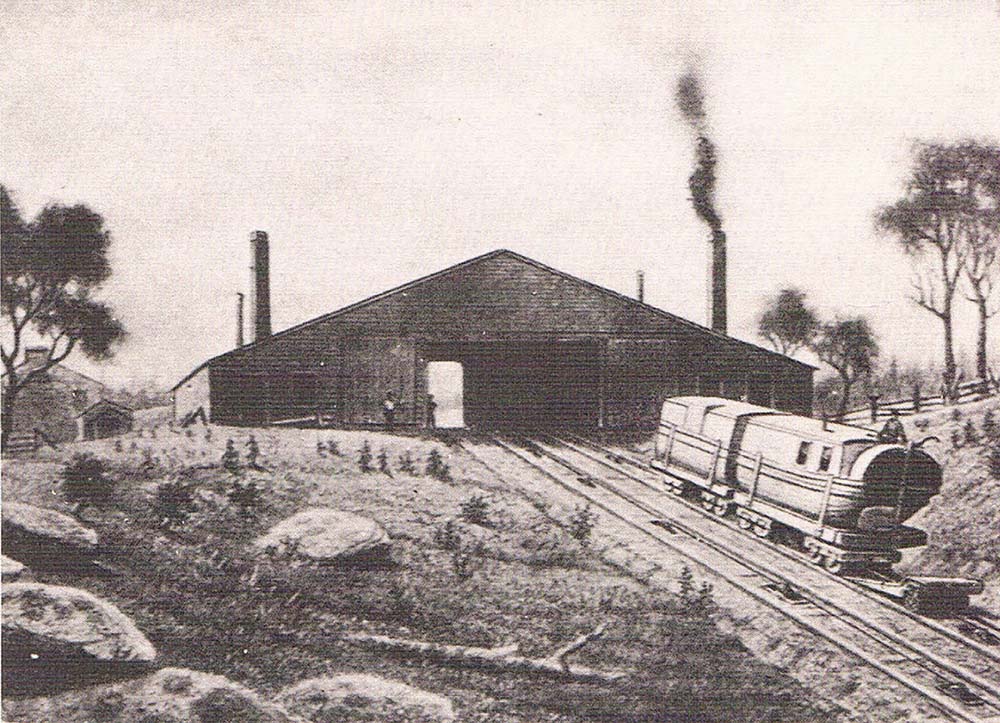
The building of a canal to link Philadelphia to Pittsburgh had to cope with the fact that the Alleghenies ran right across the line of the route. It was decided to use a series of inclined planes, but instead of linking them in the conventional way by intermediate canals, the boats would be moved along a special Portage Railway. The passenger boats were designed so that they could be divided into two halves, floated onto wheeled carriages and then either hauled up the slopes by cables or pulled on the level by horses. The illustration shows a sectioned boat ascending one of the planes. The Portage Railway was later the scene of one of America’s first attempts to use steam locomotives. (Anthony Burton)
‘ Last year, Mr. Frere, the proprietor of the ironworks, was returning from London, and going along the rail-road in a post-chaise, when about a hundred yards from him, he saw one of those wagons coming down upon him with astonishing velocity. He could not possibly get out of the way, and must have been crushed to pieces, if fortunately the waggon had not broken over the iron groove, which had hitherto kept it in the track, and run forcibly up an ash-tree by the side of the road, in the branches of which it literally stuck, and thus saved him from immediate destruction.’
The tramways were essential to many of the Welsh canals, but one man mistrusted them, as potential rivals. The Duke of Bridgewater remarked that canals would do well enough ‘if they kept away from those damn’d tramroads’. He was an accurate prophet, as we shall see in the next chapter.
One American canal combined inclines and tramways in a unique way. The canal was designed to link the Susquehanna and Allegheny Rivers, in effect joining Pittsburgh to Philadelphia. Work got under way in 1826. Two experienced engineers were brought in, both of whom had worked on the Erie Canal: James Geddes and Nathan Roberts. Their surveys showed them that it would be impractical to cross the Alleghenies by water. Work had started at both ends, and the two engineers planned to bring the eastern section up to the foot of the hills that reared up to a height of more than 2,000ft. That left a gap of 26½ miles that would be closed by a mixture of railed track and inclines – the Portage Railway. What distinguished this system from other similar mixtures was the design of the packet boats. These looked conventional enough while working on the canal, but could be divided into two parts for movement along the Portage Railway. With its various branches, the canal ran for a total of 606 miles, not just the longest in America but, with a final cost of more than $10 million, by far the most expensive.
When the line between Philadelphia and Pittsburgh finally opened in 1834, the world was already moving into a new transport era that had its origins in events that began more than a century before.