A DC motor is a class of rotary electrical device that converts electrical energy into physical motion. There are numerous types of DC motors; however, in this chapter, we will look at one specific type, which is the brushed DC motor.
Brushed DC motors are used in a wide variety of applications, ranging from toys and robotics to powered windows and power tools. Some advantages of brushed DC motors are their initial low cost, simple control, and low-speed torque. The disadvantages of these motors are their high maintenance costs and low lifespan in high-intensity environments. For the prototyping and robotic projects that we normally do with the Arduino, the disadvantages of the brushed DC motors are normally not a concern.
At the center of a brushed DC motor is a spinning armature, which contains an electromagnet. To the outside of the spinning armature is a permanent, stationary magnet. When the electromagnet in the armature is powered, a magnetic field is created that attracts and repels the permanent stationary magnets. This causes the armature to begin spinning.
To keep the armature spinning, the polarity of the electromagnet needs to be reversed. To do this a segmented copper sleeve called a commutator is used, which resides on the axle of the motor. As the motor turns, brushes slide over the commutator, coming in to contact with different parts of the commutator, causing the polarity of the magnet to switch.
The following diagram illustrates the parts of the brushed DC motor:

Brushed DC motors come in numerous shapes and sizes. Some of these motors have built-in gearboxes that can change the torque and speed that the motor will spin at. The following photograph shows some examples of brushed DC motors:

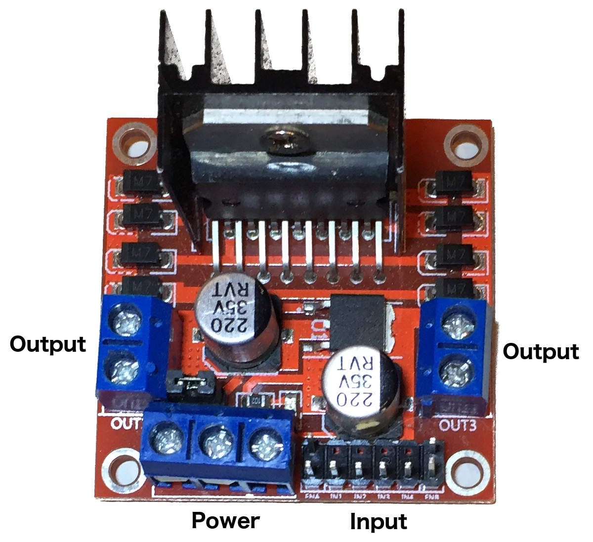
Powering a DC motor directly from the Arduino for anything other than demonstration purposes, is usually not a good idea because the voltage and current provided from the pin headers are pretty limited. We can use a motor controller to control the direction and speed of a DC motor from the Arduino while still providing an external power source to power it. In this chapter, we will look at how we can use the L298 dual H-bridge motor driver, shown in the following photograph, and also how to use the L293D chip:

The L298 motor driver enables us to control the direction and speed of two motors. This driver allows us to control motors from 5V all the way up to 35V with a maximum current of 2A. If the supply voltage is 12V or less, we can also use the 5V output to power the Arduino. The L298 motor driver has several inputs, outputs and power connectors that are labeled. These inputs from left to right are:
- ENA: Enables motor A and controls the speed of the motor
- IN1 and IN2: Controls the direction of motor A
- IN3 and IN4: Controls the direction of motor B
- ENB: Enables motor B and controls the speed of the motor
ENA and ENB normally have jumpers across the pins. In order to control brushed DC motors, we will need to remove these jumpers and connect the pin to a PWM port. The outputs are:
- OUT1 and OUT2: Output power to motor A
- OUT3 and OUT4: Output power to motor B
The power inputs, from left to right, are:
- Vmotor: Power from an external source that will be used to power the motors
- GND: Ground
- Vout: 5V output that can be used to power the Arduino
If we are building a project where we have limited space, rather than using a motor controller such as the L298 dual H-bridge motor driver, we can use an integrated chip such as the L293D H-bridge IC. The L293D chip can drive two motors, similar, to the L298 motor driver, and can power motors up to 35V with 600mA of steady current with a maximum of 1.2A. The following diagram shows the pinout for the L293D IC:

Both the L298 motor controller and the L293D chip are H-bridges. Let's take a quick look at how an H-bridge works. An H-bridge is an electric circuit that allows us to apply a voltage to our motors in either direction allowing the motor to run forwards or backwards. The term H-bridge comes from the typical graphic representation of the circuit, which looks like a capital H. The following diagram shows how an H-bridge works:

An H-bridge is usually built with four solid state switches. As we see in the preceding image, when switches 1 and 3 (I1 and I3) are open and switches 2 and 4 (I2 and I4) are closed, the right side of the motor is connected to the power supply while the left side is connected to ground, spinning the motor in one direction. If switches 1 and 3 (I1 and I3) are closed and switches 2 and 4 (I2 and I4) are open, then the left side of the motor is connected to the power supply while the right side is connected to ground, spinning the motor in the other direction.
Let's look at the parts that we will need for our projects in this chapter.