Solutions to review questions
Chapter 1
- (1) The magnetomotive force or m.m.f. is simply the product of the number of turns and the current, i.e. m.m.f. = 250 × 8 = 2000 AT. The ‘AT’ stands for ampere-turns, but strictly the unit of m.m.f. is the Ampere.
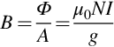
- (2) We are told that the magnetic circuit is made of good-quality magnetic steel, which is a coded way of saying that the reluctance of the steel part of the magnetic circuit is negligible in comparison with the air-gap. Under these circumstances all of the m.m.f. provided by the coil (2000 A) is available across the gap, and the flux density in the air-gap is given by Eq. (1.7) as
The question then asks about the flux density in the iron, implying that it is different from that in the air-gap. But as we have seen in the sketches (e.g. Fig. 1.7) the flux density remains the same unless the cross-sectional area changes, so the answer is that the flux density in the iron is the same, i.e. 1.26 T.
If the cross-sectional area were doubled, it would make no difference to the flux density because, as revealed in Eq. (1.7), the air-gap flux density only depends on the m.m.f. and the length of the gap. However, with twice the area, and the same flux density, the total flux would increase by a factor of two.
An alternative way of reaching the same conclusion would be to say that if the cross-sectional area were doubled, the reluctance of the air-gap would be halved, so for a given m.m.f. the flux would double. - (3) Because no information is given about the iron part of the magnetic circuit, we are expected to assume that we can ignore its reluctance, and assume that the only significant reluctances are those due to the air-gaps. This hidden message is reinforced by the use of the word ‘estimate’ rather than calculate: if the (small) reluctance of the iron parts is neglected, our values of flux density are inevitably going to be slightly on the high side.
If we denote the reluctance of the 0.5 mm air-gap by R, the reluctance of the 1 mm gap will be 2R, because reluctance is directly proportional to length. The two air-gaps are in series, so the total reluctance is 3R. The flux through both is the same, and from the Magnetic Ohm’s law is given by
To find the m.m.f. across each air-gap we apply the magnetic Ohm’s law again: so the m.m.f. across the 0.5 mm gap is given by
Similarly the m.m.f. across the 1 mm gap is given by
To find the flux density we can proceed as in question 2 and apply Eq. (1.7) to either gap. For the 1 mm gap, this yields - (4) The new rotor diameter is 299.5 mm instead of 300 mm, so radius has decreased by 0.25 mm, meaning that the new air-gap is 2.25 mm, instead of its original 2 mm. To the uninitiated, this might appear to be of little consequence. However, the reluctance of the air-gap has increased by 12.5%, so, assuming that we can neglect the reluctance of the iron parts, the m.m.f. will have to increase by 12.5% in order to maintain the same flux density.
The power dissipated in the field windings depends on the square of the current, so it has to increase by a factor of (1.125)2, i.e. 1.27. Such a large increase in heating will almost certainly be unacceptable, because unless the original cooling system had been overdesigned (in which case the field windings were running well-below their allowable temperature rise), the permissible rise will certainly be exceeded under the new conditions.
So what are the options? In the short run, the only course open is to tolerate the reduced flux density, which will be 89% of its original value. At rated armature voltage the motor will then run 12.5% above its rated speed, which can be restored by reducing the armature voltage to approximately 89% of its original value. With the same full-load armature current the full-load torque and power will then be 11% below their original values.
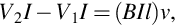
In the longer term it might be possible to add some extra turns to the field winding (if there is space!), but even then the field voltage will have to be raised to maintain the same field current. - (5) This is an exercise in applying Eq. (1.2), i.e. F = B I l. So for (a) the force is 0.8 × 4 × 0.25 = 0.8 N, while for (b) the total force is 20 × 0.8 × 2 ×0.25 = 8 N. The result for (b) is 10 times as great as that for (a) because the total current in the coil-side is 40 A.
- (6) To estimate the torque we first need to calculate the total tangential electromagnetic force, and then multiply by the radius at which the force acts. We are told that there are 120 conductors, but that only 75% of the circumference is covered by the poles: this means that only 75% of the conductors will be exposed to the radial flux density at any instant, i.e. we can assume that 90 of the 120 conductors make a contribution to the torque. We also make the very important assumption that if the conductors lying under a N pole carry positive current, those under a S-pole will be carrying negative current, so that they all contribute to torque.
The electromagnetic force on one conductor is given by F = B I l =0.4 × 50 × 0.5 = 10 N. Note that we use the mean flux density under the pole-face in this calculation: some conductors may be exposed to a slightly higher flux density than others, but we do not need the details as long as we are given the average flux density.
The total tangential force is thus 90 × 10 = 900 N. We assume that the force acts at the centre of the conductors, but all we know about the diameter of the conductors is that it must be less than 1 cm in order to fit in the air-gap. If we take the diameter as 0.8 cm, the radius at which the electromagnetic force acts will be 15 + 0.4 = 15.4 cm or 0.154 m. The torque is therefore given by T = Force × radius = 900 × 0.154 = 139 Nm. - (7) The rewound (220 V) field winding must produce the same m.m.f. as the original winding did when it was supplied at 110 V. If we are not sure how to proceed further, we can begin by arguing that, to do the same job as the old winding, the new one would probably consume the same power, in which case if the current in the 110 V field was I, the current in the 220 V one would be I/2. By progressing further with this approach, it should soon become clear whether or not we are on the right lines.
To produce the same m.m.f. with half the current the number of turns must be 2N, where N is the original number of turns. Because the current in the 2N turns is only I/2, the cross-sectional area of the original conductor can be halved, leaving the current density in the wire the same as it was in the original wire. This gives the new winding twice as many turns, but the cross-sectional area of each wire is halved, so the new winding should fit in the same space as the original one. We should now check that our initial assumption—that the power of the new one would be the same as the old one—is correct.
Let the resistance of the original winding be R: it was supplied at 110 V, so the current I was given by I = 110/R and the power consumption was (110)2/R.
The new winding has twice as many turns, so if it were made of the same wire its resistance would be 2R. But the cross-sectional area of the new wire is only half of the original, so each turn of the new coil has twice the resistance of a turn of the original wire. The total resistance of the new winding is therefore 4R. The new winding is supplied at 220 V, so the current is 220/4R = 55/R, i.e. the new current is, as expected, half of the original. The power consumption is 220 × 55/R = (110)2/R, the same as the original. So our original belief that to produce the same m.m.f., the same power would be required, is seen to be correct.
The new winding provides the same m.m.f., and contains the same volume of copper, occupies the same space, and dissipates the same power. We can conclude from this that what really matters is the amount of copper and how hard we work it (i.e. the current density): the number of turns and the cross-sectional area of wire can be chosen to suit any desired operating voltage. - (8) The discussion in question 7 related to the field windings, but the same argument can be applied to all the windings in the machine. It should therefore be clear that there will be very little external difference, except that the cable for the 110 V version would have to be thicker to carry just over twice as much current as the 240 V version.
- (9) The windings inevitably have resistance, say R. Hence when they carry a steady current (I), there is a continuous power dissipation of I2 R, and this is equal to the power supplied by the voltage source. If the field windings were made of superconducting wire having zero resistance, the steady-state power dissipation would be zero.
The energy supplied during the transient period (when the winding is first switched on, and the build-up of current is influenced by the inductance of the winding) is divided between that dissipated in the resistance as heat, and that stored in the magnetic field. Once the field is established, and the current becomes steady, no further energy is required to maintain the magnetic field. - (10) Mechanical power is given by the product of torque and speed, so a low-speed motor needs more torque than a high-speed one to produce the same power. The torque of an electrical machine (with a given sophistication of cooling system) is broadly determined by the volume of its rotor, which in turn is closely related to its overall volume. Hence for a given power a motor that runs say 10 times as fast will be 10 times smaller than its low-speed equivalent, and thus will be cheaper to manufacture. The high-speed motor will have to be geared down to provide a low-speed drive, but this still turns out to be cheaper than a direct-drive motor in most cases.


Chapter 2
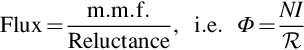
- (1) (a) Taking the bottom rail as the reference for voltages, the potential of point x oscillates sinusoidally with an amplitude of 20 V, while the potential of point y remains constant at + 10 V. The diode with the higher anode potential will conduct, thereby reverse-biassing the other one. The voltage at the load will therefore follow the sinewave while the voltage is greater than + 10 V, and be held at + 10 V at all other times, as shown by the thick line in part (a) of the figure below.
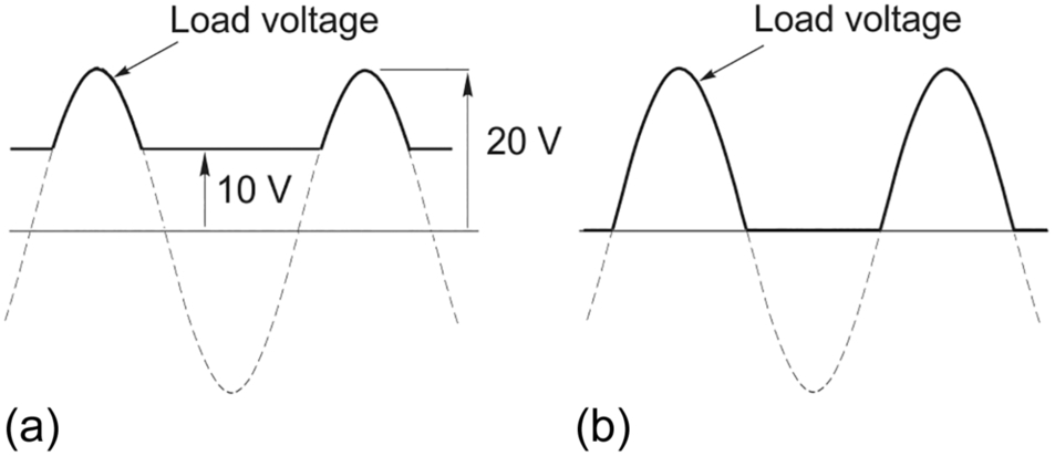
Fig. Q1
(b) This part probably needs a little more thought. If we imagine that V2 reduces gradually from the + 10 V that applied in part (a), we can see that the horizontal line in the load voltage waveform simply moves progressively downwards until it reaches zero. As this happens, the diode D2 conducts for shorter and shorter intervals. When V2 reaches zero we obtain the waveform shown at (b). We observe that whichever diode is conducting, its current is flowing upwards, and returning by flowing downwards through the load.
When V2 becomes negative, we might be tempted to think that the output voltage could become negative for part of each cycle, but this is not possible because the current would then be trying to flow up through the load and down through a diode. The diodes can only conduct from anode to cathode (i.e. in the direction of the broad arrow) so we conclude that neither diode will conduct and the waveform will be as shown in (b) regardless of the value of the negative voltage V2.
(c) Whether the diode is above or below the voltage source makes no difference since they are in series. - (2) The reference to a motor load means that there is inductance present. If, as is most likely, we can assume that the current is continuous, the mean d.c. voltage from a fully-controlled single-phase converter is given by combining Eqs. (2.3), (2.5) to yield
(If the current is discontinuous we cannot determine the voltage without knowing the load and the motor parameters.)
The maximum voltage is obtained when α = 0, giving a value of 207 V. This ignores the volt-drop across the diodes, so in practice the true figure will be nearer to 205 V. The reference to a low-impedance utility supply signals that we can neglect the volt-drop due to the supply system impedance. - (3) The mean output voltage is given by Eq. (2.6), i.e.
Substituting Vrms = 415 and Vdc = 300 gives α = 57.6°.
The frequency does not affect the formula for the average d.c. voltage, so there would be no change. - (4) This is the sort of deceptively simple question that can easily trip up the unwary. Whatever approach is taken, experience shows that it is essential to define terms clearly and proceed systematically.
We will begin by noting that the circuit is as shown in Fig. 2.8, and the output voltage waveforms for continuous-current operation are shown in Fig. 2.10. We should also recall that devices T1 and T4 conduct in one half cycle, while T2 and T3 conduct in the other half cycle.
Let us focus attention on the waveform of voltage across T1, i.e. the potential difference between its anode and its cathode. We can see that the anode of T1 is permanently connected to terminal A of the supply, so its anode is always at the potential of terminal A. So we need to see what happens to the potential of the cathode of T1 in order to sketch the voltage across it.
For the half-cycle when T1 and T4 are conducting (which we conventionally take as predominantly during the ‘positive’ half-cycle of the supply), the forward volt-drop across T1 when it is conducting will be very small, so we will assume for the purposes of sketching that we can take the ‘on’ voltage across T1 as zero for this 180° of conduction.
During the other 180° conduction period, T2 and T3 are conducting (with negligible volt-drop), so the cathode of T1 is connected—via T2—to terminal B of the supply, while its anode remains as before, i.e. connected to terminal A of the supply. The potential difference between the anode and cathode of T1 is therefore the potential difference between terminals A and B, which is of course the supply voltage, VAB. So for the second period the voltage across T1 is the supply voltage. The complete waveform of the voltage across T1 is therefore as shown in the sketch below.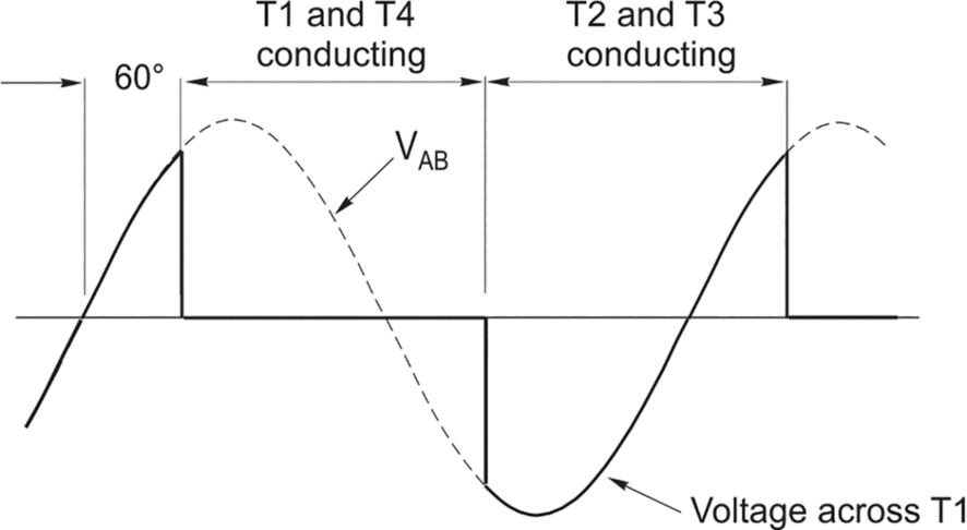
Fig. Q4 - (5) We are told that the d.c. load current is smooth at 25 A. Referring to Fig. 2.7, we recall that for one period of 180° the load current flows out from T1 and returns through T4, i.e. upwards through the supply in Fig. 2.7, while during the other period of 180° the load current flows out from T2 and returns through T3, i.e. downwards through the supply. Since the load current is constant at 25 A, the supply current is a 25 A square-wave, as shown in the figure below.
Fig. Q5
We should note that because we have ignored supply inductance (which causes the ‘overlap’ effect discussed in this chapter), the current commutates instantaneously, and the current waveform is rectangular. In practice the current takes a finite time to commutate, and the waveform is trapezoidal, but still very much non-sinusoidal and far from ideal from the point of view of the supply authorities, who do not welcome harmonic components of current!
To calculate the peak supply power we can see from the sketch that this occurs when the voltage reaches its peak, so the peak power is given by
Perhaps the easiest way to obtain the average power is to take advantage of the fact that we are told to ignore the losses in the devices. This means that the average a.c. input power is equal to the mean d.c. power, which is easy to calculate in this instance because the current is constant. When the current is constant, the mean power is simply the mean d.c. voltage (which we can obtain from Eqs. 2.3, 2.5) multiplied by the current.
Hence the mean power is given by
It is important to note that the mean power can only be obtained by multiplying the mean voltage by the current if the current is constant. If both the voltage and current vary with time, it is necessary to integrate the instantaneous power (i.e. the product of instantaneous voltage and instantaneous current) to obtain the total energy per cycle, and then divide by the period to obtain the mean power.
An alternative approach to find the mean power directly from the a.c. side exploits the fact that if, as here, the voltage is sinusoidal, the average power can be obtained by finding the r.m.s. value of the fundamental-frequency component of the current, I1; then taking the product Vr m sI1cosφ, where φ is the phase angle between the fundamental components of current and voltage.
The amplitude of the fundamental component of a square wave of 25 A can readily be shown to be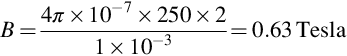 , so the r.m.s. of the fundamental component of current is
  Hence the average power is given by 230 × 22.51 × cos 45∘ = 3.66 kW, as above.
 - (6) The average load voltage is 20 V and the source voltage is 100 V, so it follows that the transistor is ‘on’ for one-fifth of the time. The load (motor) current is constant at 5 A, so the waveforms of source and load are as shown below.
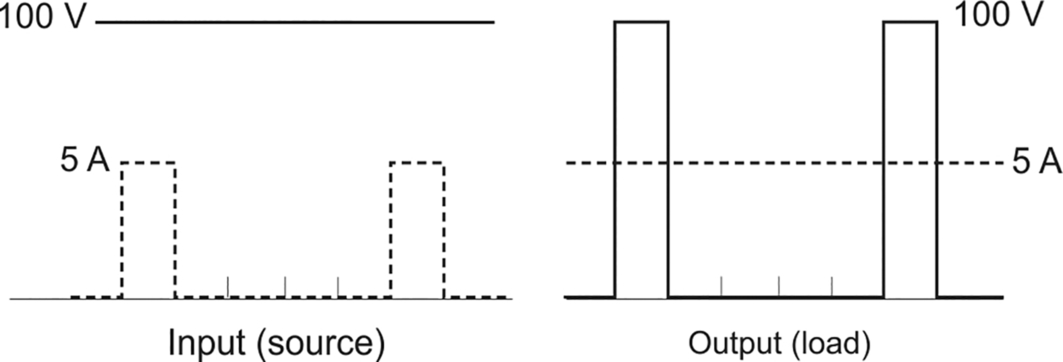
Fig. Q6
The average input current is 1 A, so the input power is 100 V × 1 A =100 W. The average load voltage is 20 V, so the load power is 20 V × 5 A = 100 W.
To draw a parallel with a transformer we focus on the average values of the input and output voltages and currents, in which case the chopper appears to function as an ideal step-down transformer with a turns ratio of 5 to 1: the secondary voltage is one-fifth of the primary (input) voltage, while the secondary current is five times the primary current. And like an ideal transformer, the input and output powers are equal. - (7) The circuit and the load voltage and current waveforms are shown in Fig. 2.4. The current is described as being ‘almost constant’, which means that we treat it as constant for the purposes of calculation.
- (i) The average load voltage is given by the product of the resistance and the average current, i.e. 8 × 5 = 40 V. The voltage waveform itself is rectangular, being 150 V when the transistor is ‘on’ and zero when the transistor is ‘off’ and the current is freewheeling through the diode. If we denote the on time (the mark) by Ton and the off time (the space) by Toff, the average voltage is given by

- (ii) Because the load current is constant, we can obtain the average load power from the product of the mean load voltage and the current, i.e. 40 × 5 = 200 W.
- (iii) We are told to treat all the devices as ideal, so there are no losses and the input power must equal the output power, i.e. 200 W. As a check, we can easily calculate the average source power because the input voltage is constant (at 150 V), so the average power is simply the product of 150 V and the average source current.
The source current is 5 A when the transistor is on, and zero when it is off. So the average source current is Hence the mean source power is 150 × 1.33 = 200 W, as above.
 - (i) The average load voltage is given by the product of the resistance and the average current, i.e. 8 × 5 = 40 V. The voltage waveform itself is rectangular, being 150 V when the transistor is ‘on’ and zero when the transistor is ‘off’ and the current is freewheeling through the diode. If we denote the on time (the mark) by Ton and the off time (the space) by Toff, the average voltage is given by
- (8) Taking the possibilities in the order given:
As there is no tendency for current to flow upwards through the switch there is no need to prevent it—and in any event a MOSFET contains an intrinsic diode that is reverse-biased during normal operation, but would allow reverse current to flow if necessary.
Inductors do not need protection from high voltages: any ‘high voltages’ present are likely to be generated by high rates of change of current through inductors anyway.
Voltage supplies are very unlikely to be subject to any restriction on the rate of change of current, but this answer may have come about as a result of confusion over the need to limit the rate of rise of current in some semiconductor devices. Where such restriction applies, an inductor would serve to limit the rate of rise of current, not a diode.
Limiting the voltage across the MOSFET is the real reason for the diode. There will be a maximum allowable voltage across the MOSFET (i.e. between Drain and Source), and if this is exceeded the device will break down. When no current is flowing in the load (Fig. Q8), the voltage across the MOSFET is equal to the supply voltage, so clearly the device must be capable of withstanding supply voltage. However, the real danger arises because of the load inductance, as discussed below.
The voltage across, and the current through, an inductor are related by the equation , i.e. the voltage is determined by the rate of change of current, or vice-versa. So if we attempt to open a switch in a circuit containing an inductor through which current is flowing, thereby forcing a very rapid rate of change of current (i.e.
  tends to infinity) a very high voltage will be developed across the terminals.
For example suppose that there was no diode in Fig. Q8, and, with the MOSFET switched on, a steady current of 2 A was flowing through an inductance of 50 mH. If we then switched off the MOSFET such that the current was reduced to zero at a uniform rate in 1 μs, the voltage across the inductor would be 100 kV! We know from Kirchoff’s voltage law that the sum of the voltages around a circuit must equal the supply voltage, so it follows that almost all of the 100 kV would appear across the MOSFET, leading to its immediate destruction.
The real problem lies in the energy stored in the inductance, which is given by If we attempt to reduce the current to zero instantaneously, we are trying to destroy energy in zero time, which corresponds to infinite power, which is clearly impossible. The alternative is to provide a mechanism whereby the stored energy in the inductor can be released in a more measured fashion, and this is where the ‘freewheel’ diode comes in. When the switch opens, the diode provides an alternative path for the current that is flowing down through the load, so the current can continue by flowing in the closed path shown at (b) in Fig. 2.4. At first the current is undiminished, so the stored energy is unchanged, but because heat is dissipated in the resistance of the load, the current decays exponentially as the energy stored reduces. The term ‘freewheeling’ arises by analogy with riding a bicycle, where, having built-up kinetic energy by hard footwork, we can rest the pedals and let the stored energy sustain our motion until friction brings us to rest.
The last answer suggesting that the diode is there to dissipate stored energy is partially correct in that some energy is indeed dissipated in a real diode (though not in an ideal one). But most of the stored energy will be dissipated in the load resistance, and the resistance of the inductor itself. - (9) We should identify the right answer (100.7 V) and explain why before speculating on the origins of the remainder.
As explained in the answer to question 8, the freewheel diode conducts when the MOSFET switches off, the load current flowing upwards through the diode. To find the voltage across the MOSFET in this condition we need to find the potential of the anode of the diode with respect to the ground reference (i.e. the bottom of the supply). We know that the forward volt-drop across the diode is 0.7 V, so the potential of the anode is 0.7 V higher than the potential of the cathode. The cathode is connected to the top of the supply, so its potential with respect to ground is 100 V. Hence the potential difference (voltage) across the MOSFET is 100.7 V. This is therefore the maximum voltage that the MOSFET has to withstand.
The figure of 99.3 V clearly comes about because of confusion over the sign of the voltage across the diode. The suggestion ‘zero’ presumably arises because it is believed that since there is no current through the MOSFET during freewheeling, its voltage must also be zero. The voltage across the load (resistance and inductance) is 0.7 V during freewheeling, because the load is (almost) short-circuited by the diode. And the suggestion that the voltage depends on the inductance is understandable but wrong because while the value of inductance determines the stored energy and therefore the duration of freewheeling, the voltage across the MOSFET will be 100.7 V regardless of the inductance.

Chapter 3
The equivalent circuit shown here should be in our minds when we tackle any d.c. machine questions:
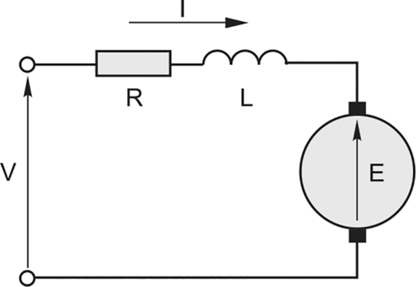
In the majority of cases we will be considering steady-state operation, so the current will be constant and therefore we can ignore the armature inductance in our calculations.
Unless told to the contrary, we will assume that the volt-drop across the brushes can be ignored.
- (1) (a) As we are not told otherwise, we are expected to assume that the question refers to the steady-state running speed, in which case the answer is that the speed is determined by the armature voltage. Justification, if required, would be along the lines below.
Whenever the speed is steady, the motor torque must be equal and opposite to the load torque. Except for very tiny d.c. motors it is safe to assume that when the motor is unloaded, the friction torque is very small, so the motor torque would also be very small. Motor torque is proportional to armature current, so we can expect the armature current of an unloaded motor to be very small, hence the term IR in the armature voltage equation V = E + IR is negligible and we can say that at no-load V is approximately equal to V. E is the motional e.m.f. induced in the armature, and is directly proportional to the angular velocity (speed), i.e. E = k ω, hence the speed is given by i.e. the speed is determined by the applied voltage.
Note that in the majority of d.c. motors the term IR will be small compared with the armature voltage V even when the motor is on load and the current I is not small, so to a first approximation we can say that the on-load speed will also be determined by the applied voltage, the speed when loaded only being slightly less than that of the unloaded motor.
(b) As discussed in the answer to question 1, the steady running current must be such as to produce a torque equal and opposite to the load torque, so in the steady state it is the load torque that determines the armature current.
(c) The answer to part (a) indicates that the steady running current is always determined by the load torque. When no ‘real’ load torque is applied, we are left with friction, due to bearings, fan, and (especially in a d.c. machine) brush friction. The friction torque is therefore reflected in the no-load current.
(d) The answers are that the drop in speed from no-load depends directly on the load torque and the armature resistance.
First, let us consider the effect of load torque. For any given load, the speed will settle when the motor torque Tm equals the load torque TL. Motor torque is proportional to armature current, i.e. Tm = k I, hence the steady current is given by , i.e. the steady armature current is proportional to the load torque. Combining the armature voltage equation V = E + IR and the e.m.f. equation E = k ω, and substituting for I from above gives the speed as
This equation shows that the no-load speed (i.e. when TL = 0) is given by , and the drop in speed that is attributable to load is given by
 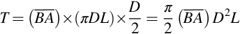 The drop in speed is therefore directly proportional to the load torque and to the armature resistance.
We note also that the drop in speed for a given load is inversely proportional to the square of the motor constant. So if we were to reduce the field current so that, say, the flux was halved to double the no-load speed, we would find that because k had been halved, the drop in speed for a given load torque would be four times as great as with full flux. This matter was discussed in Chapter 3 and illustrated in Fig. 3.12.
What the question means when it refers to ‘little ones slow down more than large ones’ really means that the percentage drop in speed between no-load and full-load is usually higher in small motors than in large ones. The reason is simply that in small machines the term IR represents a higher fraction of the applied voltage than it does in large machines.
Alternatively we could say that the reason is that ‘the per-unit resistance is higher in small machines’, meaning that the ratio is larger in small machines than in large ones.
 - (2) To reverse the direction of rotation we must reverse the direction of current in the armature or the direction of current in the field. In a separately-excited motor or a shunt motor it is usually easiest to reverse the connections to the field, because the field current is less and the wires are thinner. In a series motor, the field and armature carry the same current, so either can be reversed.
- (3) If the motor is producing more than its continuously-rated torque its armature current will be above the continuously-rated value and therefore it will overheat. If the cooling of an existing motor is improved it should be possible to increase the continuous rating without overheating, but other problems due to commutation and brush wear must be anticipated.
- (4) We can consider the no-load condition, when the motional e.m.f. E is very nearly equal to the applied voltage V. If we reduce the flux that is cut by the armature conductors, they will have to cut through the weakened flux faster to achieve the same e.m.f., so the weaker the field, the higher the no-load speed.
Alternatively we can use the result from the solution to question 1(d), i.e. that the no-load speed is given by, where k is the e.m.f. constant, which is proportional to the field flux. If the flux is reduced, so is k, leading to a higher no-load speed. - (5)
We are told that the field current is ‘suddenly’ reduced by 10%, and that the flux is proportional to the field current. (We know that the current in an inductance (the field circuit) cannot change instantaneously, so we suppose that what the question means is ‘very quickly, compared with any subsequent changes that may be initiated by the reduction in flux’.)
A reduction of flux by 10% will cause the motional e.m.f. to reduce by 10%, so the new e.m.f. is 0.9 × 208 = 187.2 V. So the new current will be given by Note that a modest reduction of only 10% in the flux causes a dramatic increase in the armature current, which jumps from 15 to 41 A.
The increased current will lead to more torque, but not quite in proportion to the increase in current because there has been a reduction in the flux. In most of the calculations in the book the flux has remained constant, in which case the torque is proportional to the current. But the torque depends on the product of the flux and the current, so if we denote the original flux by Φ, the ‘new’ and ‘original’ torques are in the ratio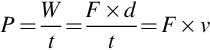 The surge of torque will lead to a rapid acceleration to the new (higher) steady speed.
 - (6) (a)
 Hence when I = 10 A, Torque = 7 Nm.
(b) The gravitational force on the mass is given by F = mg =5 × 9.81 = 49.05N. Hence the torque exerted at the motor shaft is 49.05 × 0.8 = 39.24 Nm.
The motor must exert an equal and opposite torque to achieve equilibrium, so the motor current is given by 39.24/0.70 = 56.06 A.
The stability question can be addressed by considering that, with the arm horizontal and zero net torque, we make a small change to one of the parameters and see if the system takes up a new equilibrium. If we slightly reduced the current in the motor, the load torque would then exceed the motor torque and the weight would move downwards. But as it did so the torque it exerts reduces because the line of action of the force moves closer to the axis of the motor. So when it has moved down to the point where the load torque again equals the motor torque, it will find a stable equilibrium.
However, if we slightly increase the current, the motor torque will be greater than the load torque and the weight will begin to move upwards. In so doing its line of force moves closer to the axis and the torque it exerts gets less. The amount by which the motor torque exceeds the load torque therefore increases with movement, and we have an unstable equilibrium.
So there isn’t a simple answer to the question ‘is it stable’, because the stability depends on how the equilibrium is disturbed.
(c) This is another straightforward exercise using the armature voltage equation. First we need to find the back e.m.f. which is given by Then apply the armature voltage equation V = E + IR to obtain IR = 110 − 104.8 = 5.2 V. Hence since I = 25 A, R = 0.2 Ω.
To drive a current of 56 A through 0.2 Ω when the motor is at rest (i.e. E = 0) requires a voltage of 56 × 0.2 = 11.5 V.
(d) The machine is now acting as a generator, supplying power to a system at 110 V. The generated e.m.f. E is greater than the system voltage by IR.
If the power supplied to the system is 3500 W at 110 V, the current is 3500/110 = 31.82 A. Hence the generated e.m.f. is given by E = 110 + 31.82(0.2) = 116.4 V. The speed is given by
The corresponding torque is given by 31.82 × 0.70 = 22.27 Nm.
The electromechanical power is EI = 116.4 × 31.82 = 3704 W, to which we must add 200 W to find the additional mechanical input power, and 100 W for the input power to the field, making a total of 4004 W. The useful output power, supplied to the system, is 3500 W, so the efficiency is (3500/4004) × 100%, i.e. 87.4%. - (7) In a linear system work is force times distance: in a rotary system force is replaced by torque and linear distance becomes rotary distance, i.e. angle. So in a rotary system, work is torque times angle.
Mechanical power is the rate of doing work, i.e. work/time. So in a rotary system mechanical power is torque times angle over time. But, assuming that speed is constant, angle over time is angular velocity, and power is thus given by
We have the equations T = k I and E = k ω. Hence
- (8) (a) When the motor is at rest the back e.m.f. is zero so if rated voltage (V) is applied the current will be V/Ra, where Ra is the armature resistance. In large d.c. motors the current V/Ra is very much greater than the rated current. The motor will almost certainly be supplied from a thyristor converter, in which the thyristors would not be able to withstand such a large current. So the control scheme would automatically limit the voltage applied to the motor in order to restrict the current to an acceptable level.
(b) The torque required to maintain a steady speed when a motor is unloaded is very small. The torque produced by the motor is proportional to the current, so the no-load current is very small.
The current is given by , where V is the applied voltage, R is the armature resistance and E is the motional or back e.m.f induced in the motor. As explained above, the no-load current is very small, which indicates that the back e.m.f. E is almost equal to the applied voltage. The motional e.m.f. is proportional to the speed, so the no-load speed is almost proportional to the applied voltage.
(c) When the motor is running at a steady speed, the torque it produces is equal to the load torque. When the load torque increases the previous state of equilibrium is disturbed because the load torque now exceeds the motor torque, so the net torque is negative and the system decelerates. The motional e.m.f. (E) is proportional to speed, so E reduces.
The armature current is given by, where V is the applied voltage, R is the armature resistance and E is the back e.m.f. As E reduces, the current increases, and so does the motor torque. The net decelerating torque then reduces, so the deceleration is reduced but will continue until the speed has fallen to the point where the motor torque equals the load torque, at which point equilibrium will be restored, but at a new (lower) speed. The smaller the armature resistance, the less the speed has to drop in order for the current to reach the new load level.
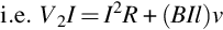
(d) The voltage equation for a field winding is , so the instantaneous power is given by
  . The first term in the power equation represents the loss of heat due to the field winding resistance, while the second term represents the rate of change of stored energy in the magnetic field.
Under d.c. conditions the second term is zero because is zero, indicating that once the magnetic field has been established the energy stored remains constant. The first term (Idc2Rf) represents the heat loss per second due to resistance (copper loss) and this has to be supplied continuously, even though none of it appears as mechanical output power. If the resistance could be made zero (e.g. with a superconducting winding) the power input would be zero once the field current had been established.
(e) If the supply to the field is pure d.c., then apart from the very short periods when the field flux is changing, the flux in the magnetic circuit is constant, so there is no danger of induced eddy currents in the body of the pole and therefore no need for it to be laminated.
When the supply is from a thyristor converter, however, there will be an additional alternating component of flux in the poles, which must therefore be laminated to minimise eddy-current losses. - (9) At the fundamental level it is true that in principle any electrical machine with rated voltage V and rated current I could be rewound to operate at voltage kV and rated current I/k, and that the rewound motor would contain the same amounts of active materials (copper and iron) and have the same performance (in particular the same power (VI) as the original.
However, in the case of the low-voltage d.c. motor, there are several additional factors which complicate matters.
The first relates to the size of the commutator. For a given power, the current is inversely proportional to the voltage, so a low voltage motor obviously has a higher current than a high-voltage one. The area of brush in contact with the commutator is determined by the current it has to carry, so the lower the voltage, the bigger the brushgear/commutator. In hand tools space and weight are at a premium so the high-voltage motor is at an advantage.
The second matter stems from the fact that the voltage/current characteristic of the carbon brushes is non-linear, so that under normal operation the volt-drop across the brushes contains a more-or-less fixed component that is of the order of 1 V, regardless of current. In a 110 V motor the loss of 1 V is not serious: but in battery-powered tools the supply voltage is only a few volts, in which case the loss of 1 V is serious, but becomes less so the higher the supply voltage. It is therefore desirable to avoid low voltages from the point of view of efficient use of energy.
The third factor relates to the properties of the semiconductor switches used in the chopper drive that provides speed control. The on-state volt-drop in transistors and diodes is (rather like the brush-drop referred to above) largely independent of the current, so that the on-state power loss is more-or-less proportional to the current. So when efficiency is important it is preferable to handle a given power at a high voltage and low current, rather than at a low voltage and high current.
Taken together these factors indicate that for a given output power the designer should aim to minimise the current, so that the higher the power, the higher the voltage. - (10) (a) We can find the machine constant from the data given in the first paragraph. When the machine is on open circuit there is no volt-drop across the armature resistances and the terminal voltage is therefore the same as the induced e.m.f. Hence using the relationship E = k ω,
The question is all about steady-state conditions, so we must expect to make use of the fact that if a linear (or rotary) system is not accelerating, the resultant force (or torque) must be zero. We can make use of this knowledge to find the tension in the rope (Fig. Q10A), which we need to know in order to work out the torque exerted by the load.
The two forces acting on the mass m are the gravitational force (downwards), equal to mg, and the tension in the rope (F) upwards. Since the descent velocity is to be constant, the net force must be zero, i.e. F = mg = 14.27 × 9.81 = 140 N.
At the drum, this (downwards) tension acts at a radius of 10 cm, so the torque exerted by the load is 140 × 0.1 = 14 Nm. We are not told anything about friction torque so all we can do is to assume it is negligible, so the total load torque is 14 Nm.
The linear speed of the rope at the drum is given as 15 m/s, the circumference of the drum is 0.2π, and the speed of rotation of the drum and machine is therefore 15/0.2π rev/s or 150 rad/s.
Because the speed is steady there is no acceleration, and the machine torque must be equal and opposite to the load torque, i.e. the machine torque must be 14 Nm at a speed of 150 rad/s.
We keep referring to the ‘machine’ rather than the ‘motor’ because in this application we are using the machine to restrain the descending load, not to drive it down. We need the machine torque to act in the opposite direction to the load torque, which it will do automatically if we complete the armature circuit with a resistance (as in Fig. Q10B), thereby allowing the generated e.m.f. to drive a current in the same direction as the e.m.f. (In contrast, if for some reason we wanted to operate as a motor rotating in the same direction, i.e. to drive down the load, we would apply a voltage greater than the e.m.f. and force the current to flow in the opposite direction to the e.m.f., yielding a driving torque rather than a braking torque.)
Now that we know the speed is 150 rad/s we can calculate the generated e.m.f. as E = k ω = 1.4 × 150 = 210 V. The machine torque has to be 14 Nm, so, using Tm = k I, the armature current must be 10 A.
The total resistance in the armature circuit is therefore given by 210/10 = 21 Ω. The armature resistance itself is 0.5 Ω, so the external resistance required is 20.5 Ω.
(b) The power dissipated in the external resistor is given by I2R = 100 × 20.5 = 2050 W, while the power dissipated in the machine armature is 100 × 0.5 = 50 W.
The electrical generated power is provided from its mechanical input power, which is derived from the steady reduction in potential energy of the lowering mass. We can check the power by considering the power (force times speed) of the falling mass, i.e. Pmech = Force × speed =140 × 15 = 2100 W.
In this question we have ignored all but the armature copper loss in order to simplify the calculations, but nevertheless the situation is representative of many real-life applications, such as dynamic braking of railway vehicles where kinetic energy is dumped in large resistors, often mounted on the roof to assist cooling.


Chapter 4
- (1) Under no-load conditions the speed of a d.c. motor is almost exactly proportional to the armature voltage, so when the speed reference is increased from 50% to 100% the armature voltage will double. Assuming the control scheme is good, the actual speed should precisely track the reference, so the new tacho voltage will be exactly twice what it was.
To compare the armature currents we would need to know how the friction torque varied with speed. As we have no information all we can say is that if the friction torque was independent of speed (a reasonable assumption for a separately-ventilated motor of the type usually employed), the no-load current will be independent of speed. Ideally the no-load current should be zero, and in practice it is seldom more than a percent or two of full-load current, except perhaps in very small machines. - (2) With a PI speed controller there will be no steady-state error in the speed, so after the transient has settled the on-load speed will be exactly 50%: the tacho voltage will therefore be the same as before the load was applied.
The torque of a d.c. motor is proportional to the armature current, so a load torque of 100% means that the armature current must be at its rated value.
If we denote the induced e.m.f. in the motor before the load was applied by E1, the corresponding armature voltage is given by V1 = E1 + I1R, where I1 is the no-load current. When the motor is loaded, the control system will adjust the armature voltage to achieve the same speed, so the induced e.m.f will be exactly the same and the on-load voltage will be given by V2 = E1 + I2R, where I2 is the full-load current. The increase in armature voltage is thus V2 − V1 = (I2 − I1)R. In practice, because the armature resistance is small, the increase in voltage from no-load to full-load will also be only a few percent of rated voltage. - (3) At first there will be a 100% speed error, so the speed controller output will saturate and demand full (rated) current to provide maximum acceleration. The current will be maintained at 100% during acceleration, so the motor torque will be constant and with negligible friction torque the acceleration will be constant so the speed will increase at a uniform rate.
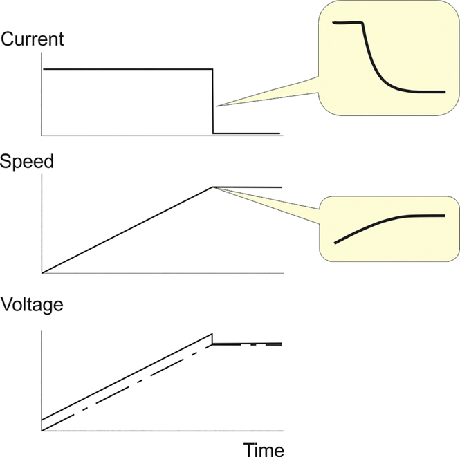
Fig. Q3
The output from the speed error amplifier will remain constant, and the current will therefore remain at full value, until the speed rises to within a few percent of the target. At this stage, the speed controller comes out of saturation and enters its linear regime, the demanded current (and the torque) reducing as the final speed is approached smoothly.
While the acceleration is constant the speed increases linearly, and so therefore does the induced e.m.f, E. The armature voltage is given by V = E + IR, so since I is held constant during most of the run-up phase, the armature voltage also increases linearly with time, as shown in Fig. Q3. - (4) (a) The drive will react to the drop in voltage (which will lead to a drop in armature voltage, torque, and speed) by reducing the firing angle a little so that the armature voltage is returned to its correct level to restore the speed to target.
A well-engineered drive will include provision for variation in the supply voltage of at least 10%, by arranging that under normal conditions the full-load armature voltage is obtained with a converter firing angle of say 15–20°. In this way, if the utility voltage should fall, the firing angle can be reduced towards zero in order to maintain the output voltage.
(b) If the tacho feedback disappears, the drive will act as if the speed was zero, so with a target speed of 50% the large speed error would cause the speed controller output to saturate and demand full current. The motor will then accelerate at full current (see answer to Q3 above) until the firing angle of the converter has been reduced to zero and the armature voltage is at its maximum possible value. The motor will then run at somewhat above base speed, drawing a small no-load current.
If the drive includes tacho loss detection circuitry it may shut-down automatically, or switch-over to armature voltage feedback.
(c) If the motor was stopped by some mechanical means, there would be a large speed error and the speed controller output would saturate and demand full current. The current controller would reduce the output voltage of the converter to a very low level because there would be no back e.m.f. with the motor stalled. A sophisticated drive would recognise that full current and no motion indicates trouble, and time-out after a few seconds at most.
(d) This would be much the same as (c), except that the output voltage from the converter would be even lower, depending on the resistance of the ‘short-circuit’. (A large stationary d.c. motor is almost a short-circuit anyway!)
(e) This is very serious, since a principal function of the inner current-feedback loop is to protect the thyristors from the danger of excess current. With no current feedback, the current controller will sense a large error, and immediately increase the output voltage from the converter in an attempt to raise the current. Given the very delicate balance that has to be maintained between V and E to avoid excessive currents, the current will inevitably shoot up sufficiently rapidly to blow the expensive fuses that are the last line of defence, but in all probability some of the thyristors will be lost. - (5) When the armature current is discontinuous, the torque-speed curve for a given converter firing angle is very poor: a modest increase in torque causes a very large drop in speed. This occurs because when the current is discontinuous, the output voltage of the converter falls substantially as the current (i.e. the load) is increased. When the load increases and the current becomes continuous, the output voltage from the converter is almost independent of the load, and the speed therefore remains almost constant over a wide range of load.
Although the undesirable effects of discontinuous current can a largely be masked by the operation of the closed-loop speed control system, it is more difficult to optimise the control system (especially the transient response) when the inherent behaviour of the motor itself varies so markedly according to the load. - (6) In dynamic braking mechanical energy is converted to electrical form and then dissipated in resistors. Regenerative braking involves converting mechanical energy into electrical energy and returning it to the supply system.
- (7) The output voltage waveform from a thyristor converter consist of rectified chunks of the incoming a.c. mains supply, as shown for example in Fig. Q7A. Ideally, since this is to be the armature voltage for a d.c. motor, we would like pure d.c. (shown by the dotted lines) but as we can see the actual waveform contains a lot of ‘a.c’ as well.
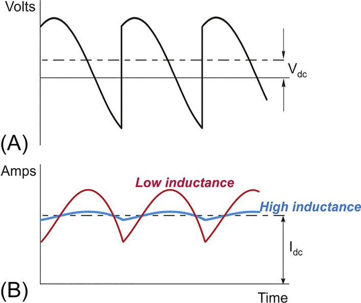
Fig. Q7
The corresponding armature current waveforms are shown in Fig. Q7B. The effect of the armature inductance is to make the current waveform a great deal smoother than the voltage waveforms, which is very desirable because the torque is proportional to the current, and we want to minimise torque pulsations. The higher the inductance, the smoother the current, as shown in Fig. Q7B. (Those who are familiar with a.c. circuit theory will explain the smoothing effect of the armature inductance in terms of inductive reactance ωL. The ‘a.c’ component of the voltage contains a series of harmonic terms (the lowest of which is 100 Hz when the supply is 50 Hz). The reactance is proportional to frequency, so higher-frequency voltage harmonics produce very little harmonic current, so the current waveform looks much smoother than the voltage waveform.)
The disadvantage of a high armature inductance is that to cause the current in an inductance L to change by an amount ΔI requires a voltage V for a time Δt such that VΔt = LΔI.
In drives, we usually want the transient response of the inner (current-control) loop to be as fast as possible, which means that we apply the highest available voltage in order to maximise the rate of change of current and minimise the time taken to achieve a given change in current. From the equation above we can see that the higher the inductance, the longer we have to apply the voltage, so in terms of transient response, the lower the inductance the better. - (8) The axes are as shown in Fig. Q8, which is the same as in the question but rotated through 90°. (The diagram in the question has the speed axis vertical, which seems to be the preference of mechanical engineers.)
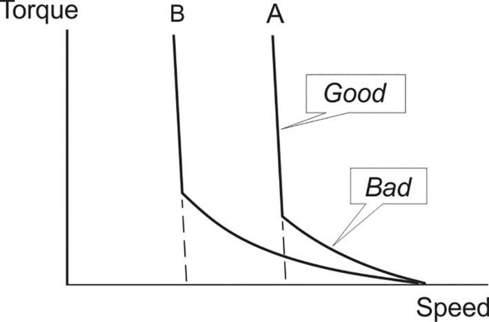
Fig. Q8
The good and bad sections are labelled in Fig. Q8: a good characteristic has only a small change in speed with load, and a bad characteristic is one in which the speed falls significantly when load is increased.
The abrupt change in character occurs at the point where the armature current changes from discontinuous to continuous. When current is discontinuous the converter output voltage depends on the current: the higher the current (i.e. the higher the torque) the lower the voltage, and hence the lower the speed. When the average current has become large enough that the current is continuous (i.e. it never falls to zero), the output voltage of the converter no longer depends on the current, and the speed is therefore almost constant regardless of the load.
We are told that the converter is fully-controlled, so the mean d.c. voltage with α = 5° is given by Vdc = Vdo cos 5∘ ≈ Vdo. There is no scale on the diagram, but we note that in the continuous current region, curve B corresponds to roughly half of the speed of curve A. The mean d.c. voltage for curve B must therefore be half of that for A, so if the firing angle is αB, then cos αB = 0.5, hence αB = 60°.
Adding additional armature circuit inductance makes the armature current smoother, and therefore reduces the likelihood of discontinuous current. The effect on the torque-speed characteristic is to extend the straight portion as shown by the dotted lines. - (9) (a) Since both motors are coupled to the same shaft, their speeds will always be the same, so to share the mechanical work we need to arrange that the torque provided by each motor is proportional to its power rating: when the original motor is at half rated torque, we want the other one to be at half rated torque, and so on.
The 150 kW drive has been chosen as the master, i.e. it has its outer (speed control) loop operational, as well as its inner current-control loop. The 100 kW drive only has its inner loop operational: its current reference is derived from that of the master.
(b) The current reference signal is fed to both drives so that when, for example, 50% of rated current is demanded in the master, 50% of the (different) rated current is also demanded from the slave.
(c) It would not be a good idea to ask both drives to operate in the speed control mode, as unless they were precisely matched, there would be a tendency for them to end up fighting one another.
(d) It could be argued that by making the slave machine current track the actual current in the master, rather than the current reference of the master, the slave current would more faithfully follow the master current. On the other hand, this would mean that if the master current control went astray, so would the slave. So on balance, it’s probably not a good idea.
Chapter 5
- (1) The maximum synchronous speed for a 50 Hz motor is 3000 rev/min, which is obtained with a 2-pole winding. A speed of 2950 rev/min is clearly appropriate for a 2-pole machine, as the slip of 1.67% is in line with our expectation that full-load slip will not exceed a few percent.
- (2) (a) The synchronous speed is given by
 The actual speed is given by N = NS (1 − s) = 1800(1 − 0.04) = 1728 rev/ min .
(b) The rotor frequency is given by
(c) The speed of the 4-pole rotor induced current wave relative to the rotor is given by
(d) The speed of the rotor induced current wave relative to the stator is 1728 + 72 = 1800 rev/min. This example illustrates the fact that the induced rotor current wave is perceived at the stator as a synchronous wave, so although the rotor currents are at slip frequency, their influence as seen at the stator takes place at the supply frequency. - (3) (a) The synchronous speed depends only on pole-number and frequency, so it is unaffected by the voltage.
(b) The air-gap flux is proportional to voltage and inversely proportional to frequency. Hence the air-gap flux will reduce in the ratio 380/440, i.e. the new flux will be 86.4% of the original flux.
(c) At all speeds, the magnitude of the current induced in the rotor depends on the magnitude of the air-gap flux wave and the slip. Hence for any given slip, if the air-gap flux wave is reduced to 86.4% the induced current will also be reduced to 86.4%.
(d) The torque is proportional to the induced rotor current and the air-gap flux, both of which have reduced to 86.4% of their original values. The torque is therefore reduced by a factor of 0.8642 = 0.746, or 74.6% of its original value.
This question illustrates the sensitivity of torque to supply voltage: because the torque is proportional to the square of the applied voltage, a modest voltage reduction produces a much more significant drop in torque. - (4) (a) A cage rotor reacts to all pole-numbers, so no modification is required.
(b) A 6-pole wound rotor reacts only to a 6-pole air-gap flux wave, so if it was placed in a 4-pole stator, there would be zero resultant e.m.f. in each rotor phase, zero induced current and no torque. (It is important to acknowledge that there will be induced e.m.f.’s in the individual coils of the rotor winding, but because of the progressive phase-shift between them the resultant e.m.f. in the complete phase-winding will be zero.) The 4-pole winding would have to be replaced by a 6-pole one in the same slots. - (5) It is almost always desirable that the magnetic circuit is fully utilised, which means that the magnitude of the air-gap flux wave should be kept at its rated value. The magnitude of the flux depends on the voltage/frequency ratio, which should therefore be kept constant.
Hence the optimum voltage for 50 Hz is given by - (6) Consider no-load operation, where the induced e.m.f. in the stator phase-winding is virtually equal to the applied voltage, i.e. in the original machine the e.m.f. induced in the winding with 15 turns per coil was 220 V.
In the rewound machine, we want the same air-gap flux wave to induce 440 V, so we will need twice as many (i.e. 30 turns) in each coil. However, for the same power, the current of the 440 V machine will be only half of the current in the 220 V machine, so the wire can be thinner. Assuming that we work the copper at the same current density, the new wire will need only half the cross-sectional are of the original, so the new diameter is 1/√2 = 0.71 mm. The total cross-sectional area of the new 30-turn coil is therefore the same as the original 15-turn coil, so it should fit in the same slot. - (7) The load torque is constant, so the motor will run at a speed such that its torque is equal and opposite to the load torque.
We must make the reasonable assumption that the motor is operating with a small slip in which case the induced rotor current is proportional to the magnitude of the air-gap flux wave and to the slip. The torque is proportional to the product of the induced rotor current and the air-gap flux.
The air-gap flux is proportional to the applied stator voltage, so if the voltage is reduced by a factor of 0.95, the flux will reduce to 0.95 of its original value. To produce the same torque the current will therefore have to increase by a factor of 1/0.95 or 105.3%.
The induced current in the rotor is proportional to the air-gap flux and to the slip. We have discovered that in order to produce the same torque when we reduce the voltage, we need the rotor current to increase by a factor of 1.053. If the flux had remained the same, this would have called for an increase of slip by a factor of 1.053. But the flux is now only 0.95 of what it was, so the slip has to increase yet more, by a factor of 1.053 × 1/0.95 = 1.108. The new slip is therefore 2 × 1.108 = 2.22%. - (8) The answer to this question is given in Section 5.3.5 in the book. Torque is produced by interaction of the air-gap flux wave and the rotor induced current wave. At low slips, these two waves are in space-phase with one another, i.e. the peak rotor current occurs at the same point on the rotor surface as the peak flux density. This is the optimum set-up for torque production, and if the two waves move out of space phase the torque reduces, reaching zero when the waves are out of space phase by 90°.
As the slip frequency increases, the rotor leakage inductance (Xr = ω Lr), which is negligible at low slips, begins to be the dominant impedance, and the rotor current therefore falls more and more out of time phase with the induced rotor e.m.f. as the slip increases. This is reflected in the rotor current wave moving out of space phase with the flux wave, to such an extent that although the amplitude of the current wave continues to increase with slip, the torque actually reduces because the extra phase-lag more than cancels out the influence of the increasing current. - (9) Flux patterns for 2-pole and 6-pole machines with identical rotor diameters are shown in Fig. Q9. If we assume that the maximum radial air-gap flux density (at the centre of each pole) is the same, it should be clear that the total flux crossing the air-gap under each pole is three times greater in the 2-pole machine than in the 6-pole machine. After crossing the air-gap from the rotor, the flux splits, with half going clockwise around the stator core and the other half going anticlockwise. The sketches show that the peak circumferential flux density in the stator iron core occurs at a point mid-way between the poles. The radial depth of the stator must be sufficient to carry this flux without the iron saturating, so given that the 2-pole stator has three times as much flux to carry it clearly has to be much deeper than the 6-pole one. (The ratio of depths is not 3:1 because of the slots, which have not been included in the sketches.)
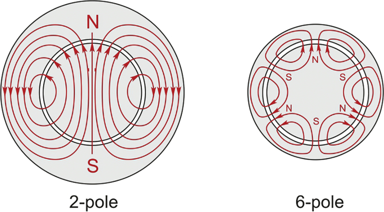
Fig. Q9 - (10) The m.m.f. waveforms are shown in Fig. Q10, and are based on the assumption that all coils consist of N turns and carry current I.
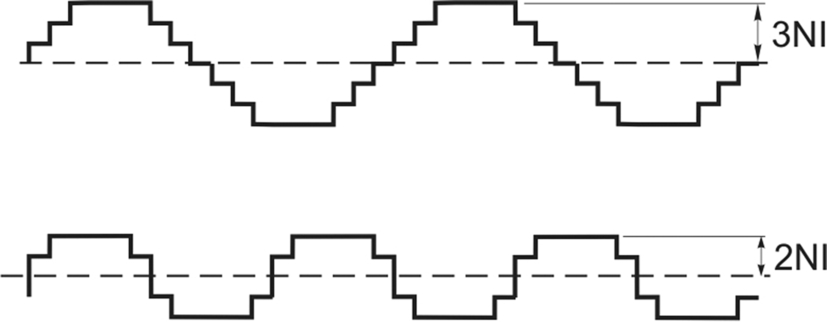
Fig. Q10
Clearly the amplitude of the 6-pole wave is only two-thirds of the amplitude of the 4-pole version, so if—as is usually the case—we want the amplitude of the air-gap flux density wave to be the same, the magnetising current (I) in the 6-pole case will have to be 50% larger than in the 4-pole case.
This example illustrates that the higher the pole-number the higher the magnetising current. We know that the magnetising current lags the voltage by 90°, whereas the ‘power’ component is in phase with the applied voltage. Hence for machines of a given power and voltage, the higher the pole-number the lower the power-factor.

Chapter 6
- (1) (a) Any supply system can be represented by an equivalent circuit consisting of an ideal voltage source VS in series with the supply system impedance, ZS, as shown in Fig. 6.1. The supply impedance is usually predominantly inductive. The terminal (system) voltage, V, is generally less than VS because of the volt-drop across the supply impedance, which is predominantly inductive. The volt-drop increases with current, but for a given current, the volt-drop is greatest when the load is inductive.
A large induction motor at rest has a very low, and predominantly inductive, impedance. When connected to the supply the current drawn by the motor will be several times the full-load current. And because the motor and supply impedances are both inductive, the fall in voltage when the load is applied will be much greater than if the load was resistive.
Other customers on the same system will experience a dip in voltage until the motor speed rises and the current it draws reduces and moves more into phase with the system voltage.
(b) If the supply system impedance is relatively high (a weak system), the volt-drop when the motor is started direct-on-line may be unacceptable to other consumers, or in extreme cases the voltage may fall so much that the motor has insufficient torque to start and/or accelerate to its normal speed. The same motor may however be started quite happily on a low-impedance (stiff) supply, where there is little or no dip in voltage even when a very large current is drawn.
(c) See the answers to questions 1 and 2.
(d) The torque developed by an induction motor at any speed is proportional to the square of the applied voltage. On a weak supply, for the reasons given in the answer to part (a), the voltage during starting will be less than it would be with a stiff supply, so the torque at all speeds will be less and the motor will therefore accelerate less rapidly and take longer to run up to speed. - (2) First, some background on 3-phase. The line-to-line voltage (referred to as ‘line’ voltage, VL) in a three-phase system is the voltage between any pair of lines. The magnitudes of all three line-line voltages are the same, but they differ in phase by 120°.
When the three windings of the motor are connected in delta (see Fig. 5.2) the voltage across each phase is the relevant line voltage. When the load (i.e. the motor) phases are balanced, the currents in all three phases have the same magnitude, but differ in phase by 120°, and as a result the magnitude of the current in the supply line is times the current in each phase. To sum up, for delta connection:
When the three motor windings are connected in star (see Fig. 5.2), then provided that (a) the three windings are balanced, or (b) the star point is connected to the neutral of the supply, the voltage across each phase is given by , and the line current is clearly the same as the phase current. To sum up, for star connection:
Turning now to the question, and thinking first about the line current, suppose that the impedance of each phase of the motor is Z.
When the motor phases are connected in delta to the supply, the current in each phase is given by and the current in each line is therefore given by
When the motor phases are connected in star to the supply, the current in each phase is given by and the current in each line is therefore given by
Comparing expressions (a) and (b) shows that the line current when the motor windings are connected in star is 1/3 of the line current when the motor windings are connected in delta.
As far as torque is concerned, we know that torque is proportional to the square of the applied voltage across each phase. The phase voltage in star is times the line voltage, so the torque in star is one-third of the torque in delta.
The torque per line ampere is thus the same regardless of whether the motor is connected in star of in delta. - (3) The motionally induced e.m.f.’s in the rotor bars are directed axially, and currents flow along the low-resistance copper rotor bars, the circuit being completed via the circumferential path provided by the copper end-rings (see Fig. 5.11). Axial current flow in the iron core is prevented because the core is made from a stack of laminations that are insulated from one another. It is however possible for circumferential currents to flow in the laminations, but the currents will be small because of the relatively high resistance of the core material.
- (4) It is usually possible to examine the end-windings to deduce the pole-number, provided that they are not completely obscured by insulating tapes. For example, in the most common (double-layer) winding the pitch (in slots) can usually be estimated by tracing the path of a top coil side from where it leaves the end of the stator core to the point at which it enters the bottom of a slot. For example if in a 48-slot stator the coil appears to span 8 or 9 slots, it is almost certain that the winding is 4-pole (full-pitch = 12 slots) with short-pitched coils of 2/3 or 3/4 pitch. On the other hand if the coil pitch was say 18 slots it would clearly be 2-pole (full-pitch = 24 slots), or if the pitch was 6 slots the winding would be 6-pole (full pitch = 8 slots).
- (5) For this question we make use of the expression for the synchronous speed, NS in terms of the pole-number of the machine (p) and the supply frequency ( f ) i.e.

- (a) If we choose a 2-pole motor the synchronous speed is
 Allowing for a modest slip of say 4% the running speed will be about 3450 rev/min, which is fine.
 - (b) At 50 Hz the synchronous speed of an 8-pole motor is 750 rev/min, so allowing for modest slip the running speed will be about 700 rev/min.
- (c) The pole-number must be an even integer, so the lowest is 2 and therefore the highest synchronous speed with a 60 Hz supply is 3600 rev/min.
If we want to reach 8000 rev/min with a 2-pole motor we would need to feed the motor via an inverter that could provide a frequency of It would be unwise to run a standard 60 Hz motor at this speed without checking with the manufacturer that it is safe mechanically. Electrically, the voltage would have to be increased in proportion to the frequency if full torque is required: this will result in high iron losses and increased stress on the insulation, so again these aspects should first be checked.
 - (a) If we choose a 2-pole motor the synchronous speed is
- (6) The synchronous speed is 1800 rev/min and the full-load slip is
The efficiency of the rotor is given by (1 − slip) × 100%, i.e. 94.4%, i.e. the rotor losses amount to 5.6%. The overall efficiency must be less that the rotor efficiency, and typically the stator losses are of similar magnitude to the rotor losses, which would suggest in this case an overall efficiency of around 89%. It is certainly highly unlikely that the stator losses are as low as 0.4%, which would be necessary to achieve an overall efficiency of 94%. - (7)
Fig. Q7 - (8) The full-load slip is
(a) For low values of slip, the torque is proportional to slip, so at half rated torque, the slip is 0.033/2 = 0.0167 and the speed is 1800 (1 − 0.0167) = 1770 rev/min.
(b) For low values of slip, torque is proportional to slip and to the square of the applied voltage. With rated voltage, the slip for rated torque is 0.033. Hence if the voltage is reduced by a factor of 0.85, the slip must increase by a factor of so the new slip is 1.384 × 0.0333 = 0.046, corresponding to a running speed of (1 − 0.046)1800 = 1717 rev/min.
When the voltage is reduced by a factor of 0.85, so is the magnitude of the rotating flux wave. In order to develop full rated torque, the induced current in the rotor must increase by a factor of 1/0.85 = 1.176 in order to compensate for the reduced flux. This means that the rotor current is 11.8% higher than its rated value, so the rotor copper loss will be increased by a factor of (1.18)2 i.e. 1.38. A 38% increase in rotor losses will cause overheating of the rotor. - (9) The stator and rotor currents are very large when the slip is large, as it is during most of the run-up period. Consequently the I2R losses are high and a substantial amount of heat is released in the windings each time the motor runs up to speed. Repetitive starting therefore runs the risk of overheating the motor, particularly if it is coupled to a high-inertia load.
- (10) The space harmonics are the unwanted by-products that are produced because the stator windings of real machines are at best an approximation to the ideal of a sinusoidally-distributed winding. When we refer to the fifth harmonic of say a 4-pole field, we mean the unwanted 20-pole field produced when we aim to produce a pure 4-pole field, and so on.
Let us suppose that the fundamental pole-number is p, and that the supply frequency is f. The speed of rotation of the fundamental field is given (in engineering units of rev/min) by the familiar formula .
.
We are told that the fifth harmonic rotates backwards at one-fifth of the speed of the fundamental, i.e. the speed of the fifth harmonic is given by . To find the frequency induced by the fifth harmonic flux wave we can use the familiar formula again, to yield
 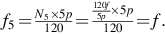 We see that the fifth harmonic reacts by inducing a fundamental-frequency e.m.f. in the stator, as indeed do all the space harmonics.
This is a result which we could have anticipated by noting that although the fifth harmonic flux wave has five times as many poles as the fundamental flux wave, it rotates at only a fifth of the speed. All points on the stator see one complete cycle of the fifth harmonic flux in the same time that they see a complete cycle of the fundamental, so both waves induce the same frequency.


Chapter 7
- (1) A speed of 400 rev/min at 30 Hz would imply that the motor had 9 poles(!): but of course the pole number must be even so we could try 10 poles, for which the speed at 30 Hz is 360 rev/min. At 75 Hz, the synchronous speed of a 10-pole motor is 900 Hz, so the 10-pole will cover the speed range comfortably.
- (2) The key here is that when the supply frequency is reduced from 50 Hz, the voltage is also reduced so that the magnitude of the air-gap flux density wave remains constant at its rated value. Under these conditions full torque is developed when the slip speed of the rotor (i.e. its speed relative to the synchronous travelling field) is the same as under rated conditions.
At 50 Hz, the synchronous speed is 3000 rev/min and the rated speed is 2960 rev/min, so the slip speed at full torque is 40 rev/min. At 30 Hz the synchronous speed is 1800 rev/min, and the slip speed for rated torque is again 40 rev/min, so the rotor speed is 1760 rev/min.
Similarly when the frequency is 3 Hz the synchronous speed is 180 rev/min, so with a slip speed of 40 rev/min the rotor speed is 140 rev/min. - (3) Because conditions on the rotor are the same as at 50 Hz, the rotor current is the same, i.e. 150 A. The rotor frequency is given by sf, where s is the slip and f is the supply frequency. The slip is given by:
 Hence the slips at 50 Hz, 30 Hz and 3 Hz are 0.01333, 0.02222 and 0.22222 respectively, yielding rotor frequencies of 0.666 Hz in each case.
Since the rotor current at rated torque is independent of the supply frequency, it follows that the corresponding referred (stator) current is also the same. In addition, the magnetising current will be the same because the flux is the same, so the total stator current will also be the same in all three cases, i.e. 60 A.
We note that the question says estimate, and this is just as well because we have chosen to ignore the iron losses, which will not be independent of the supply frequency, and which will have an in-phase component of current associated with the loss. Because we are not told anything about how the loss varies with frequency, and because the loss component of the input current will be much smaller than the load component, we can legitimately ignore it in arriving at an estimate. - (4) To a first approximation, the magnitude of the flux-density wave in an induction motor is directly proportional to the stator voltage and inversely proportional to the frequency. When the frequency is reduced to lower the running speed, it is generally desirable to maintain the flux at its full value in order to exploit the magnetic circuit to the full, and maximise the torque per ampere of rotor current. So in order to keep the flux constant, the voltage must be reduced in proportion to the frequency, i.e. the ratio V/f is kept constant.
The approximation that flux is proportional to V/f is valid provided that the volt-drop due to the stator resistance is negligible in comparison with the applied stator voltage. This is true at high frequencies, where the stator voltage is high. But at low frequencies (e.g. a few Hz with a 50 Hz or 60 Hz motor), it turns out that the stator resistance drop is comparable with the applied voltage, and therefore merely keeping the ratio V/f constant causes the flux density to be below its full value. In order to bring the flux up to rated value, extra voltage (i.e. greater than that given by the ratio V/f) is called for, and this is referred to as ‘low-speed voltage boost’. - (5) Except at very low frequencies, the magnitude of the flux density wave in an induction motor is directly proportional to the applied voltage and inversely proportional to the frequency. When the frequency is doubled, but the voltage remains the same, the magnitude of the flux density wave will be halved.
We are told that the load torque is constant, and that with the original flux, the slip speed at which the motor torque equals the load torque is 0.05NS.
The new flux is only half, so given that the induced current in the rotor is proportional to the flux and to the slip speed, we would have to double the original slip speed in order to induce the same current. However, we need twice as much current to develop the same torque because the flux is only half, so in fact the new slip speed will have to be four times the original slip speed, i.e. 0.2NS.
The new synchronous speed is 2NS, so the new slip is 0.2NS/2NS = 0.1 or 10%. - (6) We will have to be prepared to make some ‘guesstimates’ to hazard an answer to this one, and not expect to place much confidence in the answers, although the main message (that at full torque, efficiency reduces with speed) should be clear enough.
If we denote the output power at base speed as 1 p.u., we know that the input must be 1/0.8 = 1.25 p.u. so the losses at base speed are 0.25 p.u. But we have no data as to the breakdown of losses, so we will have to make some guesses.
We will begin by considering operation at full torque but half speed, and make the sensible assumption that in line with normal practice the voltage is reduced with the frequency when the speed is lowered, in order to maintain constant air-gap flux. The load torque is constant at all speeds, so, because the flux is constant, the induced rotor current will be the same and so will the referred or load component of the stator current. The magnetising component of the stator current will also be the same, so the total stator current will be the same at all three speeds. Conditions in the motor will therefore be essentially the same as at base speed and full torque, the only real difference being that the synchronous speed of the field is halved. Hence all the copper losses will be the same as at base speed, and the rotor iron losses will be the same because the slip frequency in the rotor is unchanged.
The stator iron losses will be less because the supply frequency has halved, and the windage and friction losses will have reduced because the speed has halved.
If we invoke the rule-of-thumb that says that in a well-designed motor at full load the load-dependent losses (i.e. the copper losses) are equal to the other losses (iron loss, windage and friction and stray loss), we might expect the copper loss at full torque to be 0.125 p.u. Then if we take the iron loss to be proportional to the square of the frequency, and the windage to be proportional to the square of the speed, the other losses will become 0.125/4 = 0.031 p.u. at half speed. The total loss is then 0.125 + 0.031 = 0.156 p.u. The output power is 0.5 p.u. and the efficiency is therefore 0.5/0.656 = 0.76 or 76%.
At 10% of base speed and full torque the power output will only be 0.1 p.u. The total copper loss remains 0.125 p.u. and the other losses will be very small and so we can neglect them and estimate the efficiency as 0.1/0.225 = 0.44 or 44%.
Although we cannot place too much trust in these estimates, this example nevertheless underlines the rapid fall-off in efficiency at low speeds when driving a constant-torque load. - (7) A standard totally-enclosed induction motor is designed so that at full load and base speed the shaft-driven fan provides sufficient cooling to prevent an excessive temperature rise. At low speeds, the fan is much less effective and therefore if the motor torque is high (and the stator and rotor copper losses are at their full values) there is a danger that the permissible temperature rise of the winding insulation will be exceeded.
- (8) Taking the last part first, a high supply impedance means that when current is drawn from the supply, the consequent drop in voltage at the supply terminals is not negligible, and may prove unacceptable to other consumers sharing the same supply, or exceed the statutory limits imposed by the supply authority.
Starting an induction motor by direct connection to the utility supply results in a heavy current being drawn because the impedance of the motor is very low when the slip is 1, but unfortunately, the corresponding torque may be modest, particularly if the motor has a low-resistance rotor, so the motor may take a long time to accelerate up to speed, or may even not develop enough torque to start the load. A typical high-efficiency (low resistance) motor may draw perhaps four times full-load current yet produce a starting torque less than its full-load torque.
The starting torque is low despite the high current in the rotor because the rotor current wave is out of phase (in space) with the air-gap flux wave. This happens because, when the rotor is stationary, the rotor frequency is equal to the supply frequency, and therefore the rotor inductive leakage reactance is large, which makes the rotor current wave lag the voltage wave by almost 90°. (In contrast, under normal operating conditions, i.e. at low slip frequency, the leakage reactance is negligible and the rotor current wave is in phase with the flux/voltage wave.)
In complete contrast, when the same low-resistance motor is started from an inverter, the initial stator frequency will be much less than the utility frequency, so that conditions on the rotor are ideal in terms of optimum torque production. The flux, stator and rotor currents will all be at their rated values, so full-load torque will be produced. Depending on the arrangement of the inverter, the current drawn from the supply by the inverter will be the full-load current, so there will be no overloading of the supply but the torque will probably be greater than for a direct-on-line start. - (9) When an induction motor is supplied with a non-sinusoidal periodic waveform (such as that from an inverter) we know that the behaviour of the motor is governed primarily by the fundamental-frequency component of the applied voltage. Under normal operating conditions the motor runs with a small slip with respect to the fundamental rotating field and presents a predominantly resistive impedance at the fundamental supply frequency.
As far as the higher-frequency harmonics in the applied voltage waveform are concerned, however, the slip is very high and the effective motor impedance becomes dominated by the reactances arising from the leakage and magnetising inductances: these reactances are proportional to frequency, and therefore the amplitude of the harmonic current is inversely proportional to the harmonic order. A voltage waveform with a high harmonic content thus gives rise to a current waveform with a much lower harmonic content.
In more straightforward language, the inductive nature of the motor at higher frequencies causes the current waveform to be much smoother than the voltage waveform, as shown for example in Fig. 7.1.
Chapter 8
- (1) Torque is directly proportional to rotor current when the rotor flux linkage is constant (as in vector control) so the new rotor current will be 15 A.
- (2) The vertical axis is maximum possible torque and the horizontal axis is speed. Full torque is available at all speeds up to the base speed, at which the inverter output voltage is at its maximum. At higher speeds the V/f ratio reduces with frequency, thereby reducing the flux. In this field-weakening region the maximum available torque therefore reduces inversely with frequency.
- (3) The d-axis current produces the rotor flux, which should be kept constant. The q-axis represents the torque component of stator current, so if the load torque doubles, so will the torque component.
- (4) The rotor flux linkage has to be established, which takes time because of the inherent inductance.
- (5) The acceleration is constant, so because the load is inertial it follows that during acceleration or deceleration the magnitude of the motor torque is constant; this requires the slip frequency to be maintained at 2 Hz.
Point a: the rotor speed is half of the full speed, so if the rotor was running in the steady state at this speed it would not require any torque because the load is inertial, so the steady state frequency would be 20 Hz. But because it is accelerating, and we are told that the slip frequency is 2 Hz, the instantaneous stator frequency will be 22 Hz.
Point b: negative torque is required for deceleration, so the rotor will be running faster than the synchronous speed, thereby producing negative slip and torque: the frequency at point b is thus 18 Hz.
Point c: the rotor is instantaneously at rest (i.e. zero speed) at point c, but the torque must continue to be negative so the stator frequency will be − 2 Hz at point c, i.e. the phase-sequence will be reversed. (In fact the phase sequence will have to reverse at the point where the rotor speed corresponds to a synchronous speed of 2 Hz, at which point the instantaneous frequency passes through zero.)
Point d: similar to point a, i.e. frequency 22 Hz, negative phase sequence.
Point e: similar to point b, i.e. frequency 18 Hz, negative phase sequence.
Point f: similar to point c, i.e. frequency 2 Hz, positive phase sequence.
If the motor was at rest because the speed demand was zero, any attempt to cause acceleration would be result in a demand for an opposing torque, so the person grasping the shaft would feel substantial resistance to movement. - (6) (a) The motor torque is directly proportional to the torque component of stator current, so when the torque is halved, the torque component is also halved. The flux component will be kept constant. By reference to Fig. 8.9, the original angle φ3 was 70°, so by simple trigonometry, the new angle is 53.9°.
(b) The quantities in Fig. 8.9 are not dependent on speed, so the angle will remain at 70°. - (7) The user would not normally be able to tell any difference.
Chapter 9
- (1) We should always aim to keep the working flux at its designed value. In synchronous or induction motors above 1 kW connected to a utility supply we can ignore the effect of resistance as far as flux is concerned, and safely assume that the ratio of the applied voltage to the frequency (V/f) determines the flux. For the motor in question, V/f = 420/60 = 7. Hence when we want to operate at 50 Hz, the voltage should be 7 × 50 = 350 V. Note that if we did not reduce the voltage, the flux would increase by 20%, causing the magnetic circuit to become highly saturated, with a substantial increase in magnetising current, stator copper loss, and iron loss.
- (2) With no shaft projecting at either end the set-up is clearly not intended to provide any mechanical output power, so we can deduce that one of the machines is intended to run as a motor and drive the other as a generator. The arrangement is in fact a bi-directional frequency changer, for allowing 50 Hz apparatus to be supplied from a 60 Hz system, or vice-versa.
The 10-pole machine has a synchronous speed of 600 rev/min at 50 Hz, while the 12-pole machine also has synchronous speed of 600 rev/min when it is supplied at 60 Hz. Both machines can work as motor of generator, so power can be transferred in either direction between the 50 and 60 Hz systems.
The machines could be separated and used as synchronous motors. With a 50 Hz supply, the speeds available are 500 and 600 rev/min, while these increase to 600 and 720 rev/min respectively with a 60 Hz supply. - (3) In a synchronous machine operating in the steady state the magnetic field produced by the stator windings rotates at the same speed as the rotor, so that from the point of view of an observer on the rotor there is no ‘flux cutting’ and therefore no motional e.m.f. The only time that there will be motional e.m.f. in the rotor is during run-up, or when there is a transient load change. This is important in only a limited number of cases, for example under fault conditions in very large synchronous machines connected to the power system.
- (4) The first thing that we should note is that because there is no mechanical load on the shaft of the motor, the only mechanical power being produced is that associated with any frictional or windage losses, which must be very small. So we should not be surprised to be told that the input power is always low: after all, throughout the book we have stressed that the input power is determined by the load on the shaft.
To go further we must do as suggested and make use of the equivalent circuit (Fig. 9.14) and phasor diagram. We are told that the machine is a large one, so we can make the assumption that the stator resistance is negligible without having much effect on the result.
The phasor diagram is shown in Fig. Q6. This is based on Fig. 9.16, but with the load torque reduced to zero and the losses neglected, in which case the input power becomes zero. The locus of the stator current as the rotor excitation is varied is shown by the dotted line.
Fig. Q4
Because the power is zero (or at least very small), the real or in-phase component of the stator current is always almost zero: it has been taken as zero in Fig. Q4 for the sake of simplicity.
However, the stator current (I) must be such as to satisfy Kirchoff’s law (that the applied voltage V must equal the sum of the induced e.m.f. E and the volt-drop across the synchronous reactance. Hence we see that when E is small (Fig. Q4A), the stator current is large and lagging the voltage by 90°, so that the machine looks like an inductance when viewed from the supply.
When the rotor excitation (E) is increased the stator current reduces (i.e. the apparent inductance increases) until, when E = V, the stator current is zero. Further increase in E causes the current to increase again, but his time it leads the voltage by 90°, and the machine therefore looks like a capacitor when viewed from the system. (We explained in the text that synchronous machines operating in this mode (i.e. without any mechanical power output) were widely used at one time as ‘synchronous compensators’ in power systems, allowing the power-factor of a region to be optimised by being set to have the desired value of inductive or capacitive reactance.) - (5) This is a rather vague and open-ended question, and it would be reasonable to challenge it on the grounds that we are not given enough information. However, we can answer what the questioner probably had in mind easily, by noting that initially, the motor on the right in Fig. 9.5 is in a state of equilibrium, with the rotor flux acting on the stator conductors to produce a negative (anticlockwise) torque that is equal and opposite to the positive (clockwise) torque provided by the weight.
If the stator current is then reversed, the motor torque will become positive, and will add to the torque provided by the weight, so the rotor will accelerate in a clockwise direction.
To say anything more we would have to make assumptions, perhaps beginning by assuming that the torque angle curve of the motor is independent of its velocity, so that the motor torque depends only on its position, and also that friction is negligible. In that case, the average motor torque for every complete revolution will be zero, whereas—as long as the rope remains on the drum—the load torque will always be clockwise. It follows that the average acceleration will always be positive, so the mean speed will increase until the rope finally leaves the drum, at which stage the kinetic energy of the rotor is equal to the potential energy lost be the falling weight.
Once the weight has dropped off, if friction is negligible the rotor will continue with the final mean speed being harmonically modulated by the motor toque. In a real motor, friction torque will produce deceleration, and the rotor will eventually end up with a pendulum-like damped oscillation about one of the stable zero-torque equilibrium positions. - (6) The stator winding will produce a 4-pole m.m.f. and flux distribution (N-S-N-S), and the rotor has four saliencies, so there are four equally spaced positions at which the rotor poles can align with the stator field.
- (7) The expression for torque for a given stator current is given in Section 9.3.3, i.e.
Assuming that the current is the same in both cases, the ratio of torques is thus given by
The new motor therefore produces almost just under 7% more torque. - (8) Part of a typical static torque-angle curve for a 10-pole pm motor will look like Fig. Q8, with each pole spanning 36°. Stable equilibrium positions are marked by dots, and unstable ones by a star shape.
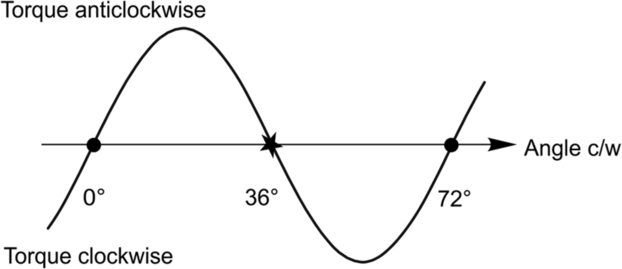
Fig. Q8 - (i) When released at any angle less than 36°, the rotor experiences an anticlockwise torque, and therefore accelerates towards the stable position at 0°, overshoots and oscillates before finally coming to rest at 0°. Conversely, if it is released anywhere between 36° and 72°, it will experience a clockwise torque and thus eventually settle at 72°.
- (ii) From the figure, maximum anticlockwise torque will be at ± 18°, and maximum clockwise torque will be at ± 54°.
- (iii) If the current is reversed, the torque-angle curve changes sign, so the stable points will now be where the unstable ones were previously. The rotor will therefore settle at ± 36°.
- (9) The torque in a pm motor depends on the strength of the magnet and the magnitude and position of the stator current relative to the magnet. Assuming that the distributions of magnet and stator (armature) fluxes are sinusoidal in space, we showed in Section 9.3.2 that the torque expression iswhere λ is the angle between the flux distributions. The magnet flux is fixed, and the armature flux is proportional to the stator current, so in order to minimise the current for a given torque, the stator current/flux should be positioned relative to the rotor so that the torque angle (λ) is 90°. If the torque angle is less than 90°, the torque could still be obtained using a larger current; with λ = 30°, for example, twice as much current would be required to produce the same torque.
- (10) The reference to base speed means that the motor voltage has reached its maximum (rated) value, and we can therefore assume that when the motor runs faster than base speed, the voltage remains at rated value. (At speeds below base speed, we would expect the V/f ratio to be constant to keep the resultant flux at its designed value.)
The motor is unloaded so once it is up to speed we can neglect losses and assume that the real input power is zero, which means that the in-phase component of current is zero. But in this case we are told that the current is negligible, so we know that the reactive component of current is also zero. Hence by reference to Fig. 9.14, the induced e.m.f. is equal to the applied voltage, as shown on the left had side of Fig. Q10. There is no armature current, (and thus no armature flux) and the resultant flux is simply that due to the magnet, and at the base frequency in this particular motor, the flux induces the e.m.f. E that is equal to the applied voltage, V.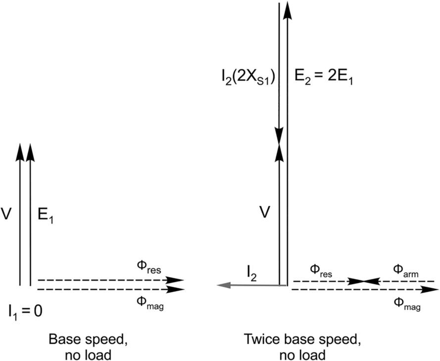
Fig. Q10
The two things that remain the same when the speed is doubled are the magnet flux and the armature voltage, and we know that the resultant flux must again induce the voltage V. But because the induced voltage is proportional to speed (i.e. frequency), we deduce that the resultant flux will be half of what it was at base speed. The armature flux must therefore oppose the magnet flux, and effectively nullify half of it, as shown in the right-hand sketch.
Turning to the time phasor diagram, we can see how the magnet flux and armature flux are reflected in the time phasors. At twice base speed, the magnet flux will induce twice as much motional e.m.f. as at base speed, so we know that in the right hand sketch, E2 = 2E1. The effect of the armature flux is represented by the voltage across the armature reactance, and we see that in this particular case the phase and magnitude of the current (I2) have to adjust themselves so that the voltage drop (I2(2XS1)) is antiphase to E2 and of half the amplitude. (Note that the reactance is proportional to frequency so it doubles with the increase in speed.)
This example illustrates the less than ideal inherent behaviour of the pm motor in the ‘field-weakening’ region above base speed. Because the motor effectively becomes over-excited (i.e. the induced e.m.f. is much greater than the supply voltage) the flux produced by the armature current has to oppose the magnet flux: this demagnetising component of the total armature current produces no useful output power, but inevitably contributes to the stator copper loss.
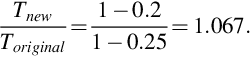
Chapter 10
- (1) In one-phase-on operation the equilibrium (rest) positions are where several rotor and stator teeth (which are usually of the same width) are directly aligned with each other. The alignment positions are therefore well-defined at the design/manufacture stage, and do not depend on the magnitude of current in the excited phase.
When two phases are excited simultaneously, the rotor comes to rest at a position intermediate between the two positions it would occupy if only one of the phases were excited. If the two exciting windings are identical and the currents are equal the rest position will be mid-way between the two one-phase-on positions. In practice, however, even if the windings are identical it is unlikely that the two currents will be exactly equal, so the final equilibrium position will tend to be slightly closer to the phase that has the higher current. The rest positions are thus less well-defined than during one-phase-on operation. - (2) Detent torque is the (small) torque that exists in hybrid motors when none of the phase-windings carries any current. It can easily be detected by turning the rotor slowly by hand with the motor unexcited. The rotor equilibrium (or rest) positions that result from the detent torque are the same as the normal step positions: this is an advantage if the motor is left unexcited, because the existence of the detent torque helps to prevent the rotor from losing registration by being inadvertently moved to another position.
- (3) The holding torque is the maximum static torque that the motor can develop, i.e. the peak of the torque/angle curve, i.e. Tmax in the typical torque/angle curve shown in Fig. 10.10. When a stepping motor is referred to as, say, ‘a 2 Nm motor’, it is understood to mean that the holding torque is 2 Nm.
- (4) We are not told the step angle so clearly the answer to this question will have to be expressed as a fraction of a step. However we know that the motor is a 3-phase one, so one step corresponds to one-third of the angle between successive stable alignment positions for one phase. Hence if we use the sinusoidal approximation suggested, the static torque can be written as T = 0.8 sin θ Nm, where θ = 360∘ corresponds to three steps and one step is represented by 120∘.
With a steady load torque of 0.25 Nm the equilibrium position will therefore be given by 0.25 = 0.8 sin θ, i.e. θ = 18.2∘. Ideally, of course the equilibrium position should be at θ = 0∘: expressed as a fraction of step, the step position error is therefore 18.2/120 = 0.15 step. - (5) When driven from an ideal constant-current source, the output torque effectively jumps instantaneously from the static torque curve of one phase onto the static torque curve of the incoming phase, the lag angle (see Section 10.5.2) adjusting such that the average motor torque is equal and opposite to the load torque. With the assumption that the static torque/angle relationship is sinusoidal, the maximum torque will be obtained when the rotor lag angle is such that the instantaneous torque follows the solid line in Fig. Q5
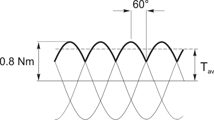
Fig. Q5
The question says estimate, so we note that the minimum torque occurs at 30° on the curve 0.8 sin θ, i.e. at 0.4, so by eye we could guess that the average is between 0.6 and 0.7: by integration the result is 0.66. The pull-out torque is therefore 0.66 Nm, and if the load torque exceeds this value, the motor will stall. - (6) If the torque/angle curve is assumed to be linear about the step position, the rotor will oscillate in much the same way as a simple pendulum as it comes to rest. Mathematically, if the restoring torque is given by T = − k θ, where θ is the angle of displacement from the equilibrium position, the equation of motion is
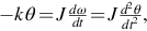 the solution of which is θ = A sin ωn t, where
We can therefore calculate the angular frequency of oscillation provided we know k, the gradient of the torque/angle curve, and the total inertia, J. We must use SI units, so we first convert 2 Nm/degree to 2 × 180/π = 114.6 Nm/rad. Substituting in the expression above yields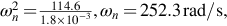 or just over 40 Hz.
 - (7) The step angle is given by:
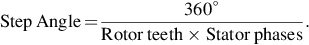
- (a) Applying this formula the step angle of the VR motor is given by

- (b) Using the same formula, the step angle is given by

- (a) Applying this formula the step angle of the VR motor is given by
- (8) Probably the easiest thing to do is to spin the rotor with the stator windings open circuited. If there is negligible mechanical resistance apart from friction, it is almost certainly a VR type. If a cyclic detent torque is evident, it must be a hybrid or a permanent-magnet type. (We have not dealt with the pm type in this book.) To be absolutely sure, the windings can be short circuited and if when the rotor is turned the mechanical resistance has increased we can deduce that the machine is acting as a generator, the currents in the windings being due to motional e.m.f. This can only happen if the motor includes a permanent-magnet to provide the excitation: the VR type has no excitation unless it is connected to the drive circuit, so it cannot generate in isolation.
- (9) When operating in the stepping mode, a hybrid motor with two phases would normally run from a bipolar supply, the rectangular one-phase-on pattern of excitation typically being + A, − B, − A, + B, + A, etc,i.e. one complete cycle of excitation of each phase corresponds to four steps.
When supplied from a sinusoidal source rather than a rectangular one, the torque will be smoother and rather than an incremental motion the rotor velocity is effectively smooth. In one cycle of the supply, the rotor will therefore move four steps, so at 60 Hz the effective stepping rate is 240 steps/s. The step angle is 1.8°, so the motor speed will be 240 × 1.8° = 432°/s or 72 rev/min. (It is interesting to note that the 1.8° hybrid motor was originally conceived to produce a low-speed utility-fed direct drive motor, offering 72 rev/min from 60 Hz or 60 rev/min from 50 Hz. The utility-fed version has more turns of thinner wire to suit the higher voltage, but is otherwise the same as the stepping version.) - (10) Perhaps it should have been pointed out to the scientist that the claim that stepping motors ‘typically complete each single step in a few milliseconds’ does presuppose that the motor was being used in a ‘typical’ application, which normally means that the load inertia is of similar order to the motor inertia.
To estimate the inertia of the pointer (which we will assume is fixed to the rotor at one end) we use the formula for the inertia of a uniformly-distributed linear mass, i.e. .
.
We will have to guess that the rotor diameter is at most 1.5 cm, and its length perhaps 6 cm. Assuming it is made of steel with a relative density of 7.8 its mass is approximately 85 g. The rotor inertia is therefore given by
We see that the load inertia is 660 times the rotor inertia, so in no sense is this a typical application.
The acceleration at the beginning of the step will be only 1/660 of what it is for the unloaded motor, and if this massive reduction applied throughout the whole step trajectory, the transit time would therefore be increased by a factor of or approximately 26 times. In practice however, the frictional damping in VR motor is low and therefore because of the high inertia the damping factor will be very low and the pointer must be expected to oscillate several times before coming to rest.
A viscous-coupled inertia damper will make matters much better, though the load inertia is so high that it may be difficult to find an ‘off the shelf’ damper that is optimum.
Chapter 11
- (1) When speed accuracy is specified as a percentage, it invariably means that the speed will be held to within that percentage of the base speed. In this case the base speed is 1500 rev/min, so 0.5% of base speed is 7.5 rev/min. So when the speed reference is set to 75 rev/min, the speed can be between 82.5 and 67.5 rev/min and yet the drive will still be within specification.
- (2) The condition that must be satisfied in order for the acceleration of the load to be maximised is that the effective inertia of the load (as seen at the motor) must be equal to the motor inertia.
In this question the actual load inertia is nine times larger than the motor inertia, so in order to reduce this as seen by the motor we must use gearing (or a toothed belt) so that the load speed is less than the motor speed. It is explained in Section 11.4 that if the gear ratio between motor (high speed) and load (low speed) is n:1, a load of inertia J at the low-speed side appears at the motor as if it were an inertia of We want an inertia of 0.009 kg m2 to appear as an inertia of 0.001 kg m2, i.e. we need
  Since the motor pulley has 12 teeth, it follows that the load pulley must have 36 teeth.
 - (3) First, consider operation at normal full load, i.e. 1 p.u. We are told to assume that the temperature rise is exponential (loose language—it really means that the temperature is given by an expression of the form (1 − e− t/T)), so if we denote the final temperature rise by Θmax, the equation governing the temperature rise as a function of time will bewhere τ is the thermal time-constant. This is sketched as the lower curve in Fig. Q3.
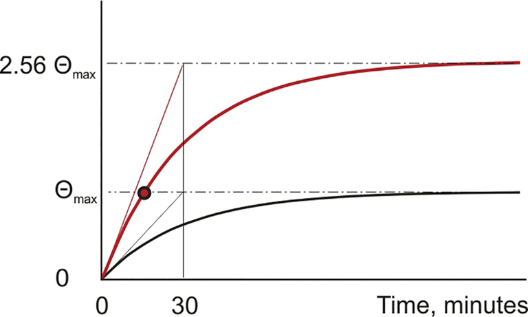
Fig. Q3
Now consider operation from cold with the motor overloaded by 60%, i.e. at 1.6 p.u. We are told that the losses are proportional to the square of the load, so the losses are now (1.6)2 or 2.56 times greater than at full load. The final temperature rise is proportional to the losses, so the final temperature rise that would be reached at 60% overload is 2.56Θmax. The equation governing the temperature rise in this case it therefore
and this is sketched as the upper curve in Fig. Q3. Putting Θ = Θmax and solving this equation gives t = 14.9 min as the time at which the temperature rise will reach the allowable limit. - (4) The scant information provided can at best allow us to suggest some possibilities. The specification will have to be much more detailed before we can home in on the best solution. But there is information that provides useful guidance, particularly as a direct drive (i.e. no gearbox) is specified. Full torque is required at all speeds, and since we know that the maximum power is about 1200 W at 10,000 rev/min, the torque is a modest 1.1 Nm.
The torque of a machine will usually give an idea of its volume, but if we have little experience we can still get some idea by noting that at the more commonplace speed of say 2000 rev/min, the output power will only be 240 W. So we might expect the size of the motor to be comparable to say a medium-range hand-held power drill.
The top speed of 10,000 rev/min is on the high side, and immediately limits the choice of motor/drive. Conventional (brushed) d.c. machines are seldom expected to run at speeds as high as this because of difficulties with commutation. A standard 2-pole induction motor could not be assumed to run happily at 10,000 rev/min when its bearings and rotor design were intended for a maximum of 3600 rev/min (on a 60 Hz supply). An off the shelf induction motor aimed at the inverter-fed market would also probably have an upper limit of something like twice the utility-frequency speed, so a special would be required to allow speeds of 10,000 rev/min.
In short, we should not expect to be able to do this job with a run-of-the-mill motor, and instead we must expect to move into the specialist area and face the inevitable higher cost. The motor manufacturer/distributer should be consulted and they would be able to offer either a specially designed induction motor or PM synchronous motor. In either case the power electronic controller would be similar, or a common design capable of controlling either type of motor. The operating frequency would not be a limiting factor.
Further matters that will have a bearing on the selection include the space available (a short fat motor or a long thin one?); the required accuracy of speed holding; the dynamic performance (i.e. what is the required bandwidth of the speed control loop); the stall protection requirements; the operating environment (will the motor have to withstand the presence of cutting fluids?, what is the ambient temperature range?); the mounting and coupling arrangements (which can be surprisingly tricky for a direct drive); and maybe several more! - (5) As far as the hoist motor is concerned, the load on the hook directly determines the steady-state torque. The maximum weight that may be attached to the hook is specified on the hoist, and it is understood that this limit is not related to the hoisting speed. It follows that full motor torque must be available at all speeds including during starting. It is often a requirement to prove that the required torque is present at the motor shaft before the holding brake is released and so full torque is also required at zero speed.
When speed control using an inverter becomes available, the operator may set the drive to lift the maximum load at a slow speed, the motor then drawing full current in order to produce full torque. In this condition the motor losses will be high but because of the low speed the cooling fan will be much less effective than at full speed and prolonged operation will therefore result in the motor overheating. The remedy will be to fit a cooling blower, or an oversized motor. - (6) Two examples of controlled-speed applications for which conventional (brushed) d.c. motors are not suitable are:
- (a) Any application in an environment where there is a danger of explosive gases being present, because of the danger of ignition caused by sparking of the commutator. The obvious area where this applies is in mining, where inverter-fed induction motors are inherently less dangerous (although they will also have to have flameproof enclosures). (D.C. motors in flameproof enclosures are available but they are prohibitively expensive.)
- (b) Any application where it is essential to minimise periodic maintenance, such as unmanned off-shore installations. The conventional d.c. motor requires regular inspection and renewal of brushes, so again an inverter-fed induction motor is likely to be preferred.
- (7) The rating of the induction motor is primarily determined by the temperature rise of the insulation material, the limit reflecting a compromise between the lifetime of the insulation and the complexity of the cooling system. After a prolonged period of operation at the full rated load, the final temperature will settle at a value that is acceptable for an indefinite period thereafter.
But because the motor is inherently capable of supplying further torque (in which case the cooling system will no longer match the increased losses), permissible patterns of short-term overload can be specified at the design stage so that, despite the temperature rising above the steady-state full-load value, no serious harm will be done to the insulation. Fortunately, the high thermal capacity of the copper and iron result in a thermal time-constant of anything from several seconds in a small motor to many minutes in a large one. Hence overloads that last for only a fraction of the time-constant can be tolerated.
The thermal issues in the inverter are similar, but with very different physical dimensions and time-scales. The vulnerable areas in any power electronic converter are the semiconductors, particular the active junction regions in the switching devices and diodes. We have seen that the on-state voltage drops are low (typically around 1 V), but the internal power dissipation can be tens or hundreds of Watts, depending on the current. This loss is produced in a tiny volume of semiconductor with very low specific heat, so the power density is very high and adequate heat removal (typically using heat sinks) is essential in order to limit the full-load temperature rise of the active material to a safe level. However, the associated thermal time-constant is very much shorter than that of the motor, so that if the current suddenly increased to provide overload power to the motor, the semiconductors would self-destruct in perhaps a few milliseconds.
The importance of discussing the potential application with the drive supplier should be clear, and the user who expects his N kW induction motor to deliver twice full load (even for short periods) should not be surprised to have to purchase an inverter rated at 2 N kW. - (8) This question relates to the rating of motors performing an intermittent cyclic duty, which was discussed in Section 11.5.2. The general approach is to rate the motor according to the r.m.s. of its power cycle, on the assumption that the losses (and therefore the temperature rise) vary with the square of the load.
We begin by estimating the r.m.s. output power. For the 1 min that the motor runs on load the torque is 60 Nm and the speed 1400 rev/min, so the power output is given by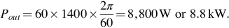 For the following 5 min the motor runs light so the output power is zero. The power-squared plot is therefore as shown in Fig. Q8.
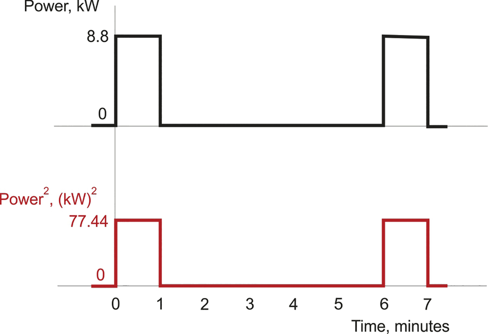
Fig. Q8
The mean of the power squared plot is given by: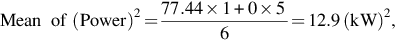 so the root mean square is 3.6 kW.
The periods of operation are certainly short in comparison with the thermal time-constant of a motor of this output, so on the basis of the continuous power rating we could choose the 4 kW, motor.
But we need to check that it would have sufficient torque during the 1-min periods i.e. 60 Nm. We are told that the pull-out torque will be 200% or 2 p.u., i.e. the pull-out torque is twice the full-load torque. We can calculate the full-load torque by dividing the output power by the running speed. Clearly, since the supply is 50 Hz, we will choose a 4-pole motor (synchronous speed = 1500 rev/min): given that the full-load slip is about 5%, we can assume that the full-load speed is 1500 × 0.95, i.e. 1425 rev/min, close enough to the desired speed. So the rated torque of the 4 kW motor is given by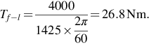 So now we know that the pull-out torque of the 4 kW motor is 2 × 26.8 = 53.6 Nm. This is insufficient to meet the requirement of 60 Nm, so a 4 kW motor will not be suitable and we must go for the next one up, i.e. 5.5 kW.
The full-load torque of the 5.5 kW motor turns out to be 36.8 Nm, so its peak torque is almost 74 Nm, which provides a good margin over the 60 Nm we are seeking to drive the pump.
The rated torque of 36.8 Nm is obtained at a speed of 1425 rev/min, i.e. a slip of 75 rev/min. We are asked to estimate the running speed at 60 Nm, so first we can assume that the torque remains proportional to slip, in which case the slip at 60 Nm will be given by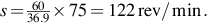 On this basis, the running speed would be 1500–122 = 1378 rev/min: but we know that between rated torque and pull-out torque the gradient of the torque slip curve reduces (see Fig. 5.25), so in practice the slip at 60 Nm will be rather more than 122 rev/min, say 140 rev/min, which means that the speed will be 1360 rev/min, which should be close enough to meet the specification.
 - (9) When the speed reference is set at 100% (i.e. not a controlled ramp) and the drive is at rest, the drive will apply full torque to accelerate as fast as possible. In most drives, full torque will be maintained until the speed comes within a few percent of the target, and only then will the torque be reduced to give a smooth approach to the final speed.
The information we are given is in line with normal behaviour, because we are told that the acceleration up to 1180 rev/min is more-or-less uniform, which means that the net torque remains constant. However, we are asked to estimate the system inertia, so we need to make use of the dynamic equation, i.e. torque = inertia × angular acceleration. But although we can calculate the rated torque of the motor, and assume that this remains constant during run-up, we have no information about friction torque, so all we can do is to make the reasonable assumption that it is small in comparison with the motor torque, and ignore it.
The rated torque of the motor is given by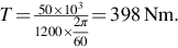
The angular acceleration is given by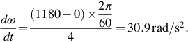
Hence the inertia is given by
To find the stored kinetic energy at full speed we use the expression
We could find the energy supplied in the first 4 s by repeating the calculation above with a speed of 1180 rev/min, but the point of this part of the question is to encourage us to recognise that when acceleration takes place at constant torque, the speed increases linearly with time and so therefore does the output power of the motor (because power = torque times speed, and torque is constant). The average power in this case is therefore half of the power at 4 s, which in turn is So the average power is 0.5 × 49.17 = 24.58 kW. The energy supplied is thus given by the average power times the time, i.e. 24.58 kW × 4 s = 98.33 kJ.
The extra 3.5 kJ represents the additional kinetic energy gained during the final part of the run-up from 1180 to 1200 rev/min. During this time the speed controller will not be saturated, and the torque will taper-off as the final speed is approached. - (10) When the motor (see question 9) is switched off completely, the only torque will be that due to friction, and because we know the total inertia we can estimate the friction torque if we know the deceleration.
The speed falls from 1200 to 1080 rev/min in 20 s so the angular deceleration is given by We know that the corresponding acceleration under full motor torque is 30.9 rad/s2, so we can express the magnitude of the friction torque as a fraction of the full-load torque as 0.63/30.9 = 0.02. In other words the friction torque is about 2% of the full-load torque, which justifies our neglect of friction in answering question 9.