8
Steering, Balancing, and Stability
Introduction
Balancing a bicycle when it is at rest is normally possible only using a special technique known as a track stand, but it is easy when the bicycle is moving forward. Like walking on stilts, balancing a bicycle derives from an ability to steer the support points to a position “under” the center of mass. Many bicycles are capable, at medium speeds, of making the necessary steering adjustments for balancing automatically, without any rider input.
A more direct way by which a rider could balance a bicycle would be to exert righting torque manually on a suitable object with large moment of inertia. The long pole tightrope walkers often carry is such an object, but hardly feasible for balancing a bicycle. If that pole is shrunk, allowed to rotate freely parallel to the bicycle’s roll axis, and geared up, it becomes a reaction wheel. As a reaction wheel rotates only when needed, it does not require much power. Balancing a bicycle manually using a reaction wheel way is just conceivable, but highly marginal. As a rough example: if while sitting on a bicycle one had a spare bicycle wheel mounted vertically in front of one like a nautical steering wheel, one would need to spin the wheel up from zero to at least 1,000 rpm within 0.1 s to correct a 5° lean. Therefore a step-up gear of about 20:1 would be required or a much heavier wheel. And once the bicycle was balanced, one would then have a spinning wheel on one’s hands, good for correcting a lean in the opposite direction to before, by braking it, but otherwise imposing a huge control problem. Balancing a bicycle with a reaction wheel is better suited for an electrical system, as demonstrated by the auto-balanced robotic bicycle of Almujahed et al. (2009) and a few existing smaller models.
A rotating mass can, however, be used also as a stabilizing gyroscope, as was done more than one hundred years ago with the two-wheeled Gyrocar and has been done many times since with various robotic bicycles. Several configurations are possible. A popular design for existing self-balancing bicycle models uses a top-heavy gyroscope with its nominal spin axis vertical, mounted in a gimbal with its horizontal axis parallel to the rear-wheel axle. Such gyroscopes must be relatively massive or spin very fast, giving considerable frictional losses and safety problems.
Neither of the systems described up to this point for bicycle balancing seem useful for purely human-powered or even hybrid bicycles, for which the conventional bicycle balancing system has now been in use for more than two hundred years, on probably billions of bicycles, and combines balancing and steering in a most elegant manner without the use of external power.
Unfortunately, the mathematics purporting to describe bicycle motion and self-stability is neither complete nor easily understandable, so design guidance remains empirical, especially as the conditions needed for self-stability and for good human handling and steering are not identical. Questions regarding the stability of tricycles and related vehicles, compared with bicycles, seem trivial, which they are at slow speeds. However, this chapter looks at some of the basic problems in regard to tricycle steering, balancing, and stability that arise at higher speeds. It also makes some simple steering-related observations and discusses the rapid steering oscillation known as shimmy.
The most visible wonder in balancing a bicycle is that the bicycle can be balanced on just two points of support. Indeed, above a minimum speed, it appears impossible to fall down even if one were to try! This is of course not so; it would be easy to crash a fast-moving bicycle, but riders obey an unconscious compulsion not to do so.
Many bicycles can self-balance or be ridden free-handed within a certain speed range. At very low or very high speeds, however, those same bicycles fall over. When a bicycle is controlled by a rider, the usable speed range is very wide, from below walking speed to well over legal speed limits.
Special Characteristics Affecting Bicycle Steering
The geometry and mass distribution of a bicycle’s steering mechanism play a significant role in the bicycle’s handling, but scientific study of such matters has been relatively elusive. Part of the reason for this is that the concepts involved in a largely self-balancing vehicle are fairly subtle, and the relevant equations are complex (i.e., difficult both to derive and to interpret). But far more important is the central role of the bicycle’s “pilot”: unlike the pilot of an airplane or even the rider of a motorcycle, the rider is by far the heaviest part of the system in bicycling and is able to use all kinds of body motions, largely unconsciously, as control inputs. Furthermore, the handling behavior that feels good to a rider is always changing, conditioned by adaptation and affected by fatigue.
There is a comprehensive received wisdom about the design features that supposedly make for good bicycle handling in a given situation (e.g., high-speed cornering or negotiating a slippery trail), and for all anyone knows, the prescriptions offered by this received wisdom may often hold true. At this juncture, what science can prescribe remains more limited in spite of ongoing progress in the field.
Wheeled-Vehicle Configurations
A wide variety of human-powered vehicles have been built. Among them are those with one wheel: unicycles (with the total center of mass higher than the wheel axle, as also with circus balls on which one can walk), large-wheel monocycles (with a lower center of mass giving slight longitudinal stability, as also with amphibious inflatable spheres or rollers with persons inside them), and the acrobatic monowheels that consist only of a hoop held by a person gyrating within. Figure 8.1 shows examples of the first two types.
Then there are dicycles, with two wheels side by side. Pedaled dicycles maintain a slight longitudinal stability by keeping the total center of mass beneath the axis of rotation. There are also gymnastics wheels for one or two persons, who are positioned inside them. Except for one type of balancing toy, there are no human powered dicycles with a high total center of mass; they are available only with electrical auto-stabilization (far easier than the auto-stabilization of a bicycle) and electrically powered.

Figure 8.1
(a) Historic unicycle and (b) sociable monocycle. (From Sharp 1896 and Harter 1984.)
By far the most popular configuration is the main subject of this book, the bicycle, for two wheels and one or more riders in line. Very rarely seen is also the bicycle for a side-by-side couple called a sociable.
Finally, there are tricycles and quadracycles. (The term quadricycle is also used, especially for motorized four-wheelers, but quadracycle seems to be favored increasingly by the manufacturers of four-wheeled HPVs.)
Besides wheeled vehicles, there are also some without wheels but with balancing characteristics at least as complex as those of wheeled ones. They can have tracks, runners or skis, feet, or rimless wheels. With very few exceptions, these vehicles are not part of this book. It does, however, devote some space to water “bicycles,” some of which balance in a manner similar to that of true bicycles.
Though modern upright bicycles and tricycles appear very similar when viewed from the side, they have distinctly different characteristics:
- • Bicycles must be balanced, requiring some skill, especially to mount them and get them moving. Tricycles and quadracycles, in contrast, are innately stable at rest.
- • When traction (adhesive friction) is good, bicycles can easily corner at high speed. Balance is maintained by leaning. Side forces on the wheels are relatively small, so the wheels need only small amounts of stiffness and strength against lateral forces. Most tricycles cannot lean, so fast cornering is possible only by “hiking” one’s body to the inside of a turn to avoid rollover (figure 8.2). Wheel side loads are then large, except in the case of special leaning tricycles that tilt the wheels in the direction of the center of the turn. Recumbent tricycles are at an advantage here, having both a lower center of mass and mostly smaller, stronger wheels.
- • When traction is poor, bicycle balance can easily be lost, often resulting in a crash. Tricycles are less affected by slippery conditions.
- • A bicycle’s single track makes it far easier to avoid or pass obstacles such as potholes or stationary cars and to negotiate very narrow paths than it is to do so on a tricycle with its three tracks.
- • A bicycle’s narrow width makes it easier than a tricycle to carry up stairs and over or around obstacles.
- • Even though a bicycle must operate in a state of balance, this balance is easily achieved even with offset mass, because the lean angle can always be adjusted to place the center of mass over the support line. An extreme case of such an adjustment is found in a sociable two-person bicycle with one rider heavier than the other. Rather than the heavy side’s sinking down, balance is attained by raising that side comically higher!
- • A side slope or cambered road has an effect on both types of vehicle that is quite similar to that of a steady turn. It has almost no effect on a bicycle but gives rise to an annoying steering torque on a tricycle and side force on its rider—or in extreme cases, the risk of rolling over.
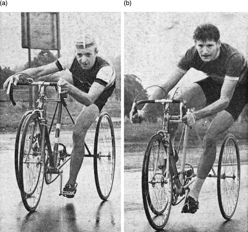
Figure 8.2
Cornering tricycles. (From Cycling and Sporting Cyclist, September 14, 1968.)
- • On a tricycle that has two coaxial wheels like a dicycle or a bicycle trailer, misalignment may cause one wheel to direct the vehicle slightly to one side, against the resistance of one or more others, with the potential for substantial rolling resistance and wear. Very accurate alignment, optimum steering alignment in turns, or a self-aligning caster arrangement may prevent these ill effects.
Broomstick Analogy
A bicycle balances when its center of mass (CM) is over its support. At rest or in steady horizontal motion, “over” means vertically above. But in horizontally accelerated motion, such as a steady turn (imagine sitting in a fast-turning merry-go-round), “over” means at an angle, such that the combination of downward gravitational pull and horizontal centrifugal force aims directly from the bicycle’s center of mass to the point at which it is supported, as in figure 8.3.

Figure 8.3
Definition of “the center of mass being over the support” when a bicycle travels around a curve. The cross-sectional diagram shows the center of mass CM traveling in a circle of radius RT at speed V (at a right angle to the cross section, here “into the paper”). The virtual point of support is on a line between the two tire contact patches. The movement imposes an apparent outward centrifugal force of m V2/RT on the center of mass and can be added as a vector to the weight m g (mass m × ~9.81 m/s2) to give the resultant force F = m g/cos θL (the lean angle). The real force is that provided by the tires, which causes an inward centripetal acceleration V2/RT. The radius to use is that at the center of mass and not that at the tires. However, this radius is initially unknown, so an exact analytical solution is more complicated than that given here. For the bicycle to be in balance, F must go through the point of support, and the clockwise torque y m V2/RT around this point must be counteracted by a counterclockwise torque x m g of the same magnitude, which is achieved when x/y = tan θL. On a horizontal surface, the reacting ground force must be composed of a vertical component −m g supporting the weight and a lateral component −m g μ, in which μ is the minimum required coefficient of friction for the tire not to slide laterally on the surface and is therefore equal to tan θL.
An examination of the simple exercise of balancing a broomstick upright in the palm of the hand can elucidate many important aspects of bicycle balancing. The key rule is that unstable balance of an unstable rigid body requires an accelerated support. Whether its support point is at rest or moving steadily, a broomstick inverted and placed on the palm of the hand is unstable and will simply fall over. (A gyroscopically stabilized top is a quite different case.) Balancing a broomstick (or a bicycle) consists in making the small support motions necessary to counter each fall as soon as it starts, by accelerating the base horizontally in the direction in which the broomstick is leaning, enough so that the acceleration reaction (the tendency of the center of mass to get left behind) overcomes the tipping effect of lack of balance. The base must be accelerated with proper timing to ensure that the rate of tipping vanishes just when the balanced condition is reached. Even more sophisticated control is needed to maintain balance near a specified position or while moving along a specified path. Taller broomsticks fall less quickly than shorter ones, the time it takes being proportional to the square root of the height above the support. Therefore, high-wheeled bicycles are actually rather easy to ride, but getting on and off is another matter!
How Bicycles Balance
A rider balances a bicycle in the left-right direction by steering it while rolling forward so as to accelerate the support of the bicycle laterally. Restraining a bicycle’s steering makes it unrideable, a fact that is put to good use in steering locks for deterring bicycle theft. Surprisingly, the small steering motions necessary to right a bicycle after a disturbance can take place automatically, even with no rider, as releasing a riderless bicycle to roll down a gentle hill and then bumping it can demonstrate.
It was and often still is widely believed that the angular (gyroscopic) momentum of a bicycle’s spinning wheels somehow supports it in the manner of a spinning top. This belief is absolutely inaccurate. Gyroscopes can react against (i.e., resist) a tipping torque only by continuously changing heading. For example, a tilted top can resist falling only by continuously reorienting its spin axis around an imaginary cone. Locked steering on a forward-rolling bicycle does not permit any wheel reorientation, and the bicycle will fall over exactly like a bicycle at rest, no matter how fast it travels or how much mass is in the wheels. To be sure, bicycle wheels actually are changing heading continuously whenever the steering is turned, but their mass is small compared to the “mass times acceleration times center of mass height” moment that predominantly governs bicycle balancing.
Still, there is an extremely interesting gyroscopic aspect to bicycle balance: the angular momentum of a bicycle’s front wheel urges it to steer (i.e., to precess) toward the side on which the bicycle leans, as can be demonstrated by lifting a bicycle off the ground, spinning the front wheel, and briefly tilting the frame. In other words, the gyroscopic action of the front wheel is one part of a system that automatically assists the rider in balancing the bicycle. If the angular momentum of this gyroscopic action is canceled, as Jones (1970) did with an additional counterrotating front wheel, considerably more skill and effort are needed for no-hands riding.
The broomstick analogy presented in the preceding section is actually only partly applicable to a bicycle, as a bicycle is supported at two distinct points that generally accelerate somewhat differently. A low-speed slalom maneuver after riding through a puddle demonstrates that the front wheel travels a much wavier path than the rear, which also lags in phase (figure 8.4). Only in a steady turn do the contacts of both wheels with the ground follow paths of comparable curvature, yet the front wheel’s turning radius (RF) is greater than that of the rear (RR) by the amount (½ RF2 RR). Therefore, lateral acceleration (equal to V2/R or equivalently to V times the rate of change of the wheel heading [e.g., in radians per second]) is generally greater for the front contact than for the rear. In fact, only at the front of the bicycle frame can lateral acceleration be brought about relatively rapidly, by accelerating the steering angle and by maintaining a rate of increase of steering angle. The steering angle must settle to a steady value before the front acceleration reduces to match the rear.

Figure 8.4
Front-wheel track compared to that of the rear. Note that the front-wheel track is wavier.
One implication of the delayed and reduced lateral acceleration of a bicycle’s rear contact is that, when the bicycle is moving, mass over the front contact is more easily balanced than that over the rear. If mass is to be carried over both contacts, keeping that in the rear lower than that in the front will allow the front-support acceleration to exert more control over balance. (Rear steering would make the rear contact the more controllable one, but a rear-steering bicycle is difficult to ride fast.)
The basic means by which bicycles are balanced and controlled involves vehicle supports that travel only in the direction in which they are pointed (implying that they can support loads perpendicular to that direction). For this, at least one wheel must be steerable, usually the front one. This balancing-by-steering function can be performed not only by conventional large-diameter bicycle wheels (or their equivalent as shown in figure 8.5), but also by small-diameter wheels, as on a foldable scooter, by skates on ice, by skis or runners on snow, and by fins or foils in water. It is even possible to tip a three- or four-wheeled vehicle up on the wheels of one side and to balance and steer it like a bicycle or motorcycle for as long as desired. In each of these cases, the required steering torque may differ, and the particular sideslip, inertia, or flex may affect the feel, but with regard to steering, all are essentially bicycles.
Countersteering to Generate Lean
An unstable balanced object like a broomstick or bicycle must have the appropriate (say) leftward lean to maintain significant acceleration leftward of the center of mass. In other words, the support point must first move to the right of the system center of mass to create a leftward lean. The motion of the support point can be hard to observe while riding, because it happens so quickly and unconsciously. To see it most clearly, one can ride a bicycle along a painted line and watch the front wheel’s position while making a quick maneuver to change lanes rightward. One will notice a brief leftward deviation of the front wheel’s path, caused by briefly steering leftward before settling into a sustained rightward steer angle (figure 8.6).
But in fact every cyclist knows so-called countersteering very well, unconsciously: it is the only possible way to maneuver a bicycle or to stop with the right degree of lean to allow whichever foot the cyclist chooses to touch the ground. That everyone who knows how to ride a bicycle already unconsciously understands the method becomes clear when one is riding close to the edge of a curb or a slight drop-off. Riding closer to either of these than about a handspan makes one feel nervous and “trapped”: one knows that it will be necessary to turn toward the danger in order to steer away from it. If there’s no room, one senses that trying to escape will take one over the edge. Nonetheless, it is useful to practice (obviously completely separated from other traffic) abrupt, forced countersteering, for use in emergency maneuvering (see, e.g., Forester 2012).

Figure 8.5
Bicycle with booted spokes. Bicycles can be perfectly adequately balanced and steered not just with the use of large wheels, but also using very small wheels, skis, or as shown here, spokes with boots on them! (Photo by Jean Gerber.)

Figure 8.6
Brief leftward “countersteering” to generate the rightward lean necessary for rightward turning.
Countersteering is also required when one encounters a side-wind gust or when one is pushed by a neighboring rider. Whenever any force pushes one to the right, one must briefly turn right to generate leftward lean, so as to counter that force steadily.
Incidentally, all principles of unstable balance apply to runners too. To accelerate, runners lean forward, and to decelerate quickly, they lean back, by getting their feet out in front. Running straight and then suddenly turning leftward requires a step to the right in order to generate lean.
Basic Bicycle-Riding Skills
At the height of the 1890s bicycle boom, bicycle-riding schools sprang up in major cities. But for most reading this book, who acquired bicycling skills at a later time, learning to ride was typically a trial-and-error process conducted near home. Does the study of bicycle balance offer any insight into the process?
- • The common advice to “turn toward the lean” is good. US Patent 5,887,883, to Joules, describes a quick method for teaching this.
- • It’s hard to see how training wheels can inculcate any of the desired balancing habits, unless the training wheels are off the ground (i.e., used only when at rest). This has largely been realized as time has gone on, and nowadays, instead of training wheels, young children are often given simple foot-propelled bicycles without pedals, in order to build up their balancing skills before their pedaling skills, which tend to come more easily.
Beyond these thoughts, the commonsense idea of having those learning to ride a bicycle adjust the bicycle’s seat low enough to plant their feet on the ground and practice by coasting down gentle, grassy slopes is indeed an attractive one. Also, a scooter is an excellent tool for learning to balance, almost free of the risk of a fall, as stepping off onto the ground is easy.
Once basic balancing of a bicycle has been mastered, important cornering techniques can be developed:
- • Paying attention to surface conditions that provide poor traction or influence the steering (e.g., loose gravel, wet leaves, snow and ice, railway or tramline crossings). As these cannot always be avoided, practicing their negotiation at slow speeds and suitably protected is recommended.
- • Adopting the gentlest possible turn radius (i.e., starting wide then grazing the apex of the curve). Riders must be prepared to brake hard before entering a turn if their speed seems to be too high to enable them to complete the turn safely.
- • Gripping the bicycle’s handlebars more tightly when cornering hard at high speed, to stiffen the arms and to reduce instability, and also when negotiating uneven surfaces.
- • Holding the inside pedal in a raised position during hard cornering, so that it does not strike the pavement. The limit of cornering traction on good dry pavement is typically at 40° lean or greater, but a bicycle’s inside pedal held low or moving typically strikes the pavement at 30–35°. Holding the bicycle more upright than the upper body places more stress on the wheels but may allow continued pedaling through a corner without slowing. (On a bicycle equipped with a freewheel, this technique is optional; on a fixed-gear bicycle, it is essential.)
Cyclists often extend the inside knee in executing a turn, like hard-cornering motorcyclists. This practice offers the seemingly marginal benefits of making the bicycle’s frame slightly more upright, keeps a little more of the tire central tread on the pavement, and counters the tendency of a steered wheel’s mechanical trail (defined in figure 8.8 and later in the chapter) to shrink because of lean. Snapping the leg inward momentarily decreases side force and may enable recovery if the rider loses traction during the turn. However, many skilled riders do the opposite when coasting: they “lean the bike” more than the body and put weight on the outside pedal, which automatically puts it into a safe position for cornering. As the tires’ camber is increased, this technique could provide extra cornering force and permit a tighter turn. Other skilled riders suggest keeping everything in line as much as possible, and yet others that it doesn’t matter. Videos of champion racers show that in a way all three techniques can be applied at the same time: outside foot down, extended inside knee, twisted torso with head more outside, and center of mass nearly in line with contact patches (figure 8.7).

Figure 8.7
Typical high-speed cornering attitude of a champion racer, with approximate center of mass. On lesser curves the inside leg may be tucked in.
History of Balancing and Stability Research
The foregoing observations should make the basic way bicycles balance clear, as it already was to Karl von Drais two centuries ago. Since then and until this day many researchers have tried to determine the exact mechanisms through which bicycle balancing is accomplished, as well as mathematical expressions for describing them. Most have had the right ideas but have also made mistaken assumptions or errors in trying to find elegant solutions. Arend Schwab’s (2009) bicycle dynamics history page lists most of these attempts up to 2005 and his main page (2017) those until recently. For a long time gyroscopic action was considered essential, if not for skilled riders, at least for the automatic balancing of riderless bicycles. Front-wheel steering with mechanical trail was regarded similarly. In 1970 D. E. H. Jones tried to find answers by building unrideable bicycles to disprove preliminary assumptions. He installed an off-ground counterrotating front wheel as an “antigyro.” Not only was the resulting vehicle still rideable, but it also still balanced automatically when given a push, and thus it disproved the myth that gyroscopic action is necessary for a bicycle’s front wheel to self-steer.
In 1985, research on bicycle balancing and stability began at Cornell University, with Jim Papadopoulos in Andy Ruina’s lab. Papadopoulos 1987 represents the state of research then and Olsen and Papadopoulos 1988 is a well-presented short summary. In 1988 Richard Hand published his thesis with further research, confirming much of the previous work, but still hadn’t found a complete and error-free solution to describe bicycle balancing. With few exceptions, not much more research emerged over the subsequent decade and a half, until renewed interest in 2002 commencing with Arend Schwab of Delft University visiting Andy Ruina’s lab and later undertaking bicycle research in his own lab. In 2004, the third edition of this book included an introduction to many equations regarding bicycle dynamics that are still in use today. In 2005 Åström, Klein, and Lennartsson of Lund University published a very nice article, but still apparently with errors or contradictions of previous and later work. The next years saw frequent student research, and in 2011 the US-Dutch team of Kooijman, Meijaard, Papadopoulos, Ruina, and Schwab managed to build a riderless bicycle with no trail and tiny, nongyroscopic wheels, demonstrating conclusively that a bicycle’s mechanism for balancing and self-steering does not need wheels with trail or gyroscopic action, given the right mass distribution causing the bicycle to automatically steer into a fall. Schwab and Meijaard (2013) review the group’s and others’ work up to this date. The team also built a rear-steering bicycle, which worked both with and without a rider. Videos of the models and further papers are available at Schwab 2017. An important resource is Ruina 2014, with copies of many papers up to this date.
Thanks to all this research work, it is clear today that certain aspects of bicycle geometry, including trail, mass distribution, and gyroscopic action, all play a part in bicycle stability. None of these aspects is uniquely important, but with the right combinations, auto-stable bicycles are possible, and the wrong combinations will result in unstable, perhaps even unrideable bicycles. For bicycle designers, this information is still not very useful, as the equations involved remain complicated and do not lend themselves to “bicycle-cookbook”-type design formulas. A computer-program, JBike6, accessible through Dressel 2015, is, however, available for determining the speed range within which a particular bicycle is self-stable.
Effect of Bicycle Configuration on Steering and Balancing
Some of a bicycle’s steering and balancing behavior can be explained in terms of basic geometry: the placement of the wheels, possibly of differing radii, the line of the steering axis, and the centers of masses of the front (steerable) and rear assemblies. In figure 8.8, a horizontal distance called the wheelbase (LW) separates the bicycle’s two wheels. The bicycle’s steering axis, shown as a dashed line, forms an angle with the horizontal surface on which the bicycle rides that is known as the head angle (λ) and typically intersects with the ground just ahead of the front-wheel contact. (In some calculations, λ is instead measured from the vertical, as in figure 8.11.) The line of the steering axis commonly passes below the front-wheel axle, that is, the bicycle’s fork is bent forward.
The bicycle’s front axle is ahead of the steering axis by a perpendicular distance referred to as the fork offset (LFO). This distance is sometimes also called rake, an unfortunate usage, as in motorcycling this term is used for the angle of the steering axis from the vertical. The horizontal distance by which the front-wheel contact is behind the imaginary point where the steering axis intersects the ground is called trail (similar to automotive caster). A related quantity is the shortest (perpendicular) distance from the front-wheel contact to the steering axis (positive when the axis is ahead of the contact point), which is called mechanical trail (LMT). A further relevant quantity, shown in figure 8.11, is the wheel flop (sometimes wheel-flop factor), the distance by which the front assembly is lowered if the front wheel is rotated 90° about the steering axis (or raised, in the case of negative trail).

Figure 8.8
Bicycling parameters related to handling and stability.
The various geometric features described in the last two paragraphs are difficult to measure, but they have such a great effect on handling and stability that we have tabulated some values for a number of different large-wheeled bicycles in table 8.1. It is apparent that as one moves from (particularly stable) touring bicycles to road-racing and finally track bicycles, the head angle becomes steeper and the amounts of trail and wheel flop decrease. Note that a bicycle’s fork offset is increased to reduce its trail. Various online calculators are available that allow quick comparisons between the parameters; Jim G. provides a nice one at yojimg.net/bike/web_tools/trailcalc.php that provides values for trail, mechanical trail, and wheel flop. These quantities are also easy to work out manually; the formulas are given, for example, at en.wikipedia.org/wiki/Bicycle_and_motorcycle_geometry.
Table 8.1
Mechanical trail and wheel flop for the angles and offsets of typical bicycles
| Bicycle type | Head angle to road, degrees | Fork offset, mm | Mechanical trail, mm | Wheel flop, mm |
|---|---|---|---|---|
|
Touring |
72 |
47.5 |
58.5 |
18 |
|
Touring |
72 |
50.7 |
55.2 |
17 |
|
Touring |
73 |
57.9 |
42.3 |
12 |
|
Road racing |
74 |
50.0 |
44.5 |
12 |
|
Road racing |
74.5 |
55.1 |
36.5 |
10 |
|
Road racing |
74 |
66.9 |
27.6 |
8 |
|
Track racing |
75 |
52.1 |
36.7 |
9 |
|
Track racing |
75 |
65.4 |
23.4 |
6 |
Note: All bicycles included in the table have a wheel radius of 343 mm.
The values shown in table 8.1 represent the results of the fine-tuning of conventional bicycles to obtain the greatest suitability and handling for their intended purpose. These are more general qualities than stability in balancing and steering, but they are related. The process of bicycle design must satisfy different requirements, starting with riders’ ability to put at least one foot down on the road when the bicycle is stationary, their being able to pedal without hitting the front wheel in turns (track racers can tolerate this to some extent), or the bicycle’s ability to carry cargo. Thus special-purpose bicycles, even with conventional large wheels, may have different angles and offsets from other bicycles. Many e-bicycles, for example, place the battery between the seat tube and the rear wheel, thus lengthening the bicycle. However, the geometrical parameters for most large-wheeled bicycles are rather similar. Vehicles with small wheels, recumbents, and those with unusual designs can have completely different configurations from the typical one. For bicycles with suspension, possible changes in geometry must also be kept in mind, for example, when braking.
Small Wheels and Special Configurations
Whereas the design of conventional bicycles with large wheels has for generations been in the hands of large companies and also countless frame builders, HPVs, including recumbents, velomobiles, and cargo bikes, mostly have at least one smaller wheel and, being relatively new and few, are the subject of avid research and experimentation by small companies, universities, and individuals. Accordingly there has been a great evolution in design, and there is much variability among type and models in the parameters that influence balance, steering, and handling. Unfortunately, there are few design tools or published guidelines to assist builders in achieving optimum designs right from the beginning.
The Basic Design Problem for Recumbents
The basic design problem for recumbents, in particular, is a bit different from that for upright bicycles. Putting the feet (or sometimes even the hands) on the ground for balancing at rest is no problem in recumbents (except for ultralow ones), but to avoid, in a turn, a collision between the steered front wheel and the pedaling feet, this wheel must either be well in front, resulting in a long wheelbase, or somewhere under the knees, yielding a short wheelbase. Normally a smaller wheel is required in either case, say, one nominally 0.4 m in diameter. Long-wheelbase recumbents are delightfully stable at speed, but difficult to maneuver when moving slowly in tight places like city traffic. Short-wheelbase recumbents, on the other hand, are more maneuverable but can seem a bit skittish at speed, as only tiny steering motions and little torque are required (as also with many upright small-wheeled and short folding bicycles). Between long-wheelbase and short-wheelbase recumbents are compact long-wheelbase recumbents, described in chapter 10, which are both easy to ride and stable because of their especially small front wheels and high seating positions. For all configurations, achieving optimum angles and offsets can make the difference between “just rideable” and “enjoyable” or “safe.”
One Systematic Research Project
The adjustable recumbent Multilab test vehicle of Rohmert and Gloger (1993) at the University of Darmstadt systematically explored balance and steering in recumbents. Multilab was a short-wheelbase recumbent with two 400 mm wheels and an adjustable wheelbase (but nominally about 1 m), head angle, and track. It also featured a special “mirror-symmetrical” front-wheel geometry with the head angle pointing backward but a large negative fork offset in order to achieve a normal trail. Such a geometry results in “reverse wheel flop,” that is, the wheel doesn’t flop at all, but is stable in a neutral position.
Two components essentially determine whether and how strongly a wheel actually wants to flop:
- 1. The load on the front assembly, which tries to find its lowest potential energy, that is, lowest point of the total center of mass.
- 2. The center of mass of the front assembly itself, which becomes noticeable when the cyclist is dismounted and holding the unloaded bicycle by the seat.
Because of the way Multilab is designed with respect to these two components, its required steering torque as a function of the steering angle is greater than for the conventional geometry (see figure 8.9). Rohmert and Gloger (1994) evaluated six different configurations with nineteen test subjects who ranked them on six points of handling quality. All were able to ride the Multilab within minutes, and the best-rated configuration, with a head angle of 89° (i.e., 91° measured in the conventional direction) and a trail of 59.5 mm (requiring a negative fork offset of 62 mm and resulting in only −1 mm wheel flop), got an average of 7 out of 10 possible points (“somewhat good”). Rohmert and Gloger gave the advantages of this configuration as a larger possible collision-free steering angle with the pedaling feet and a longish wheelbase without an excessive overall length and thus more stability in braking and with obstacles and crosswinds. They subsequently used this concept in their DESIRA-2 single-track velomobile with a wheelbase of 1,080 mm, a head angle of 88° (i.e., 92°), and a track of 40–50 mm (for a 16-inch × 1.75-inch tire), but we know of no other implementations since.

Figure 8.9
(a) Mirror-symmetric fork geometry (from Rohmert and Gloger 1993) and conventional geometry (dotted lines). Note the larger fork offset required. (b) Conventionally the steering torque increases as a result of trail and decreases with large angles because of wheel flop. In the mirror-symmetric geometry, both trail and wheel flop work in the same direction.
Some Other Configurations
There are a number of other very different configurations for short-wheelbase recumbents that are rear or center steered. A good reason for rear steering is to have the front wheel fixed so that it can be a bit larger and still fit between the cyclist’s swinging legs and also be driven, avoiding a long chain (some designs even put the pedal axis through the front wheel axis using special hub gears). Schnieders and Senkel (1994) provide an overview of rear-steering recumbents and interesting numerical stability plots. They conclude that rear-steered recumbents are rideable but not self-stable. Indeed, quite a few videos of various rear-steered recumbents can be found, in which they appear to be rideable but do not seem very stable. However, a video of a talk by Arend Schwab at TEDxDelft2012, “Why Bicycles Do Not Fall” (linked from Schwab 2017), shows a student-designed rear-steered bicycle in action, both with a rider and also self-stabilized. Schwab and Kooijman presented a rear-steered high-speed racer at a 2014 conference, and in 2017 P. H. De Jong completed a master’s thesis on rear-wheel steered bicycles at Delft University of Technology.
Some bicycles pivot from the center. Perhaps the most famous is the original Flevobike, which is steered by leaning and with the legs via the pedals, which are attached to the front assembly. This arrangement can leave the hands free, and the Flevobike is extremely maneuverable once mastered (but can otherwise be “self-folding”—even while riding!). An internet video, “Flevobike Crashtest,” shows a dozen consecutive test falls on gravel. (More remarkable than this extreme example of instability is the passive safety shown: the totally unprotected crash rider—in shorts—seems to suffer a single minor elbow scrape.) A further remarkable video, “Flevobike & Difficult Riding Situations,” shows advanced riding, including track stands and slow, hands-free maneuvering. This Flevobike model is no longer in production, but it still has many enthusiasts, who are united at flevofan.ligfiets.net, with links there also to various home-built variants. (A similar Flevotrike was also produced.) Figure 8.10 shows a side view of the Flevobike and its dimensions, as well as the similar, large-wheeled, center-steered Airbike. (There even exists a center-steered [vertical-axis] upright bicycle, the Snaix, that is advertised as a training device.) Also shown in figure 8.10 is the center-steered Python (2018) tricycle with a unique, huge negative trail. Python-lowracer.de/geometry.html describes the advantages of the Python’s geometry, which gives a large negative (self-centering) wheel flop, referred to as seat rising here.
Patterson (1998; see also calpoly.edu/~wpatters/lords.html) attempted to provide guidelines for standard front-steered recumbents, which he used for some years in his class on single-track dynamics at California Polytechnic State University. (This class was later continued; see Davol and Owen 2007.) His approach was to find simplified equations describing good handling, meaning optimum parameters for steering movement and torque. He devised six parameters and a value he called sensitivity, meaning the rate of a recumbent’s frame roll (rear assembly) in relation to the control motion at its handlebars. Patterson gives recommended minimum and maximum values for these seven parameters, plus trail and fork-flop force, based on practical experience. They are not very complicated and readily entered into a programmable calculator or spreadsheet. The idea is to enter an initial bicycle geometry, then vary aspects of it until the all parameters fit into the recommended ranges.

Figure 8.10
(a) Flevobike with pivot angle 40°, trail 130 mm, and wheelbase 950 mm; (b) Airbike with pivot angle 50°, trail 190 mm, and wheelbase 1,070 mm; (c) Python with pivot angle 65°, trail −300 mm, and wheelbase 1,290 mm. (Drawing by Jürgen Mages, licensed CC-BY-SA-3.0.)
Patterson’s goal was to enable anybody with a calculator to predict the handling qualities of front-steered recumbents, but at least college-level mathematics and considerable motivation to grapple with the method are still required. Archibald (2016) has since presented Patterson’s method in a more accessible manner with examples and in addition makes a Matlab script available.
Zero-Radius Wheels
For many analytical purposes, the radii of a bicycle’s wheels are not significant. A simple model with the same contact points and steering axis as real wheels involves just tiny “zero-radius” wheels (see figure 8.11). Such a model effectively freezes the mechanical trail LMT at a fixed value, whereas on an actual bicycle, LMT is somewhat reduced during hard cornering.
A variety of observations based on this simple model can easily be understood:
- • Riding straight while bending the torso to the right side of a bicycle’s frame requires the frame to lean leftward to maintain balance (i.e., center of mass over the line joining the contact points). The vertical support force on the front contact then has a component perpendicular to the wheel; this component acts through the lever arm of the mechanical trail and tends to turn the handlebars to the right, as can easily be felt. The small effect of handlebar weight simply adds to this torque (see figure 8.12).
- • When riding a bicycle at low speed (e.g., 2.5 m/s) in a circle, being careful to keep one’s torso in the plane of the frame, and controlling the handlebar position with just one finger, it is clearly necessary to restrain the bicycle from sharpening the turn. This characteristic is primarily a reflection of the system’s potential energy being at a maximum in the upright, straight configuration. When the handlebars are turned, the center of mass falls by an amount proportional to the mechanical trail (equivalently, with the mass center at a fixed height, turning the handlebars would lift the front contact off the ground). The resulting torque cannot be demonstrated at rest because of tire friction. As is discussed later in the chapter, the tendency to sharpen a turn is part of bicycle self-stability.

Figure 8.11
Model of a bicycle with point (i.e., zero-radius) wheels. If the bicycle is held level and the steering is turned, the front wheel will lift off the ground. If it is free in pitch and the steering is turned 90°, the front assembly will fall by the distance labeled Wheel flop. The figure shows, therefore, that the front wheel of a stationary but loaded and unbraked bicycle (or tricycle) will tend to flop to one side, usually in addition to a small torque produced by the location of the front assembly’s center of mass.
- • Low-speed turns to the right place the front contact to the left of the frame plane; to retain balance the frame must therefore lean left. In low-speed turns, therefore, the frame leans to the outside. Only above a certain minimum speed (defined approximately by V = [g LMT tan ΘL]1/2) does the bicycle frame actually lean toward the center of the turn.

Figure 8.12
Steering torque from frame tilt when riding straight: (a) rear view; (b) side view. The center of mass will be over the support line connecting the wheel contacts. The vertical force at each wheel can be resolved into two components parallel and perpendicular, respectively, to the wheel plane. The ground force (F) supporting the front wheel tends to turn it leftward, with moment F LMT sin θL. In addition, the scrub torque at the front contact and the handlebar weight also promote leftward steering.
In no-hands riding, and if gyroscopic torques and special tire contact-patch torques are ignored, the bicycle’s center of mass is at its maximum height in the balance plane defined by the center of mass and the two ground contacts. The handlebar torque is zero (i.e., the steering is in the balanced orientation). The tendency of the bicycle to turn to one side, or equivalently the need for torso lean to keep it traveling straight, is in this case a sensitive indicator of various asymmetries. At moderate speeds, the principle that the steering can achieve equilibrium only by turning against any disturbing torque can predict no-hands handlebar orientation qualitatively. Here are some examples:
- • Applying a clockwise (rightward) torque bias to a bicycle’s steering (e.g., with a taut rubber band from the seat post pulling on a string wrapped around the steering axis) ultimately leads to the steering’s being turned counterclockwise (i.e., a leftward turn). Alternatively, the rider’s torso must lean to the right of the frame, so frame lean creates a countering leftward torque.
- • Intentionally misaligning a bicycle’s front wheel relative to the forks (say, bottom displaced to the left of the rider and top to the right) also creates a steering torque initially tending to turn the handlebars (rightward, in this case). In equilibrium they are therefore turned leftward: the bicycle curves to the left. Misaligning the rear wheel so that its forward edge is moved rightward also generates leftward steering.
- • Torso lean to the left of a bicycle’s frame tilts the frame to the right, generating a torque tending to turn the steering right. The equilibrium configuration therefore involves steering to the left. Relative to the frame’s midplane, the cyclist leans in the direction of the intended turn and then straightens the torso to return the bicycle upright.
However, all these zero-radius-wheel models (and also those assuming three-dimensional but rigid tires) leave out the potentially important contribution of tire scrub torque: because of the finite size of its contact patch, a vertical wheel traveling in a circle requires a steering torque to keep it going around a turn. Scrub torque arises as a result of this turning, because an element of the tire at the front of the contact patch is moving inward relative to its path of travel, and an element at the rear of the patch is moving outward.
Correcting the Straight-Line Steering Torque of an Imperfect Bicycle
A bicycle that is not perfectly symmetrical generally requires an annoying steering torque, or an upper body lean, to travel straight when ridden with no hands. (A bicycle may of course be constructed asymmetrically on purpose, as was a bicycle for ladies sitting sideways, made by Ariel in 1872.) It is conventional to check a bicycle’s wheel alignment by placing a straightedge at two points of the rear wheel near ground level (i.e., parallel to the intersection of the wheel plane and ground plane) and determining whether the front wheel grazes the same straight-edge when turned parallel to it. But this test alone cannot indicate whether straight-line riding on the bicycle will require a steering torque.
Straight-line riding requires only that the ground traces of the bicycle’s wheels (i.e., the line of intersection of each wheel plane and the ground plane) be parallel. In that condition, with the bicycle in balance, steering torque arises whenever the steering axis does not pass directly above the front contact or does not pass directly below the front-assembly center of mass. Any of a number of factors (load imbalance, wheel tilt or offset, steering-axis misplacement) can give rise to steering torque, and any other of those same factors can be altered to reduce or cancel that torque. It’s probably simplest just to make every component of the bicycle symmetric in the usual sense.
Stability
One of the questions related to bicycling that can be studied via equations involves a bicycle’s intrinsic stability: When does an uncontrolled bicycle automatically tend to ride straight and upright?
In the field of dynamics, stability has a precise meaning. For the purposes of the discussion here, a steady motion (such as rolling straight and upright) is stable if, after it is disturbed, it eventually settles down to being steady again. In the technical sense, a well-aligned riderless conventional bicycle with freely turning steering bearings is stable over a range of speed that depends on its design (say, 3–6 m/s). If it is bumped while it is in motion, it will soon return to straight upright running. The nature of its stability is defined by a settling time (how quickly the disturbance dies away) and possibly a frequency, if the system (e.g., the steering) tends to oscillate while settling down to steady motion. Note that nothing in this entire section addresses the question of suspension, which of course can further change bicycle (or vehicle) behavior.
Unfortunately, hands-off stability with no rider input of any kind does not seem to have much to do with a bicycle that feels stable. For example, all standard (uncontrolled) bicycles and motorcycles lose stability both at low speeds (when they execute greater and greater weaving oscillations) and also theoretically at high speeds (when they fail to recover from a turn and instead progressively increase their lean and turn angles in a spiraling crash). But no competent rider has much cause for complaint when riding a typical bicycle at speeds between 2 and 15 m/s.
Experienced cyclists actually seem to redefine the technical term instability to mean “oversensitivity to small input torques.” That is, a bicycle could be perfectly stable at a certain speed with a no-hands rigid rider and yet might seem too skittish, or even unsafe, if each little shift of body weight or hand pressure caused a large steering deviation, as has been suggested by Andy Ruina; this idea also forms the basis of Patterson’s method.
Having offered some caveats about the limited significance of technical stability studies, we still find it interesting to ask when an uncontrolled bicycle is stable. It’s an intriguing scientific question and may help in identifying more important issues regarding bicycle handling (see Society of Automotive Engineers 1978 and 1979, two important collections of papers on motorcycle-related stability).
Bicycle-dynamics equations can reveal no-hands and uncontrolled stability by any of several routes:
- • By direct simulation (i.e., instant-by-instant numerical solution of the involved differential equations) to calculate the motion of a bicycle starting from a small initial lean. Inspection of the simulations results can reveal whether the bicycle straightens up or crashes. It doesn’t really matter what the small initial disturbance is (e.g., a lean, bump, or wind gust): an unstable bicycle will almost always wobble or fall, and a stable one will always straighten up. The disadvantage of this approach is that it is hard to determine general rules from specific cases (see Roland 1973).
- • If constant-coefficient equations are solved exactly by standard algebraic methods, stability is revealed by the resulting eigenvalues (exponential growth factors). These are generally complex numbers, their real parts (x-coordinates) reflecting growth tendency, and their imaginary parts (y-coordinates) indicating oscillation frequency. If their real parts are all negative, then steering disturbances decrease over time, whereas if any one eigenvalue has a positive real part, then its corresponding pattern of disturbance is predicted to grow infinitely. This approach has disadvantages similar to those of the previous one: the algebraic eigenvalue formulas are too complex to use, so eigenvalues are generally determined numerically for specific cases of interest.
- • If the main interest is in identifying a simple criterion of stability, and not the details of a bicycle’s motion as it either straightens up or crashes, then the Routh-Hurwitz stability criteria may be employed. According to these criteria, if four specific algebraic quantities (functions of velocity and bicycle parameters) are all positive, a given bicycle will be stable. If a bicycle is stable at a certain speed, then altering the design or the speed may destroy that stability. Loss of stability is revealed by monitoring just two of the four quantities. Some conclusions of this approach follow.
Nonoscillatory Instability
The simplest criterion for establishing a bicycle’s stability is just the condition that in a steady turn, it should try to sharpen its steering angle. In other words, the steady-turn handlebar torque required of the rider must be such that it restrains the steering from turning further. If an uncontrolled bicycle lacks this property, it never pulls itself out of a turn but gradually increases its lean and steering angles while following a tighter and tighter spiral, a phenomenon referred to in the motorcycle-stability literature as capsizing.
In a conventional bicycle, the steering geometry and the front-assembly center of mass position, which together tend to increase any steering angle if the bicycle is balanced, afford turn-sharpening behavior at low speeds. But at high speeds, gyroscopic “stiffening” effects reduce the steering’s geometry-based turn-sharpening tendency. Because a bicycle’s steering axis is not vertical, some of the “tipping” torque needed to overcome the front wheel’s gyroscopic resistance to continually changing its heading must be supplied through the handlebars. At low speeds, the required steering torque is minuscule, but when the bicycle is traveling faster, it significantly reduces the geometry-based tendency of the steering to sharpen the turn. Finally, at a critical “inversion” speed, there is theoretically no need for steering torque or upper-body lean to hold any turn. Above the inversion speed, the bicycle’s steering will tend to self-center, thus reversing the ordinary sense of required handlebar torque or torso lean.
In principle, all conventional bicycles and motorcycles possess a steering-torque inversion speed, and above this speed they will display the mild nonoscillatory instability described earlier (i.e., they will capsize). For typical ridden bicycles, this speed is in the range of 5–8 m/s. But in actual bicycle riding, torque reversal and instability are not very apparent.
The tendency of an uncontrolled bicycle to capsize at high speed is not a matter for concern to most riders. The instability that results from this tendency is so slight that it takes many seconds to develop, and riders’ slight unconscious upper-body motions probably suffice to compensate for it.
However, at low speeds, violation of the turn-sharpening criterion for stability through poor design causes an uncontrolled bicycle to capsize far more quickly. Since gyroscopic effects are then negligible, the requirement is for maintaining stability in a poorly designed bicycle essentially static and may be stated in either of two equivalent ways:
- • The upright, straight bicycle must be at an absolute maximum of potential energy with regard to any combination of reasonable steering and lean angles.
- • A stationary, balanced bicycle, if its handlebars are turned while balance is maintained, must lower its center of mass, or equivalently, must generate a steering torque that tends to increase the steering angle.
A bicycle with a vertical steering axis and negative fork offset to produce a trailing front contact does not satisfy these requirements. With the bicycle at rest, steering the front wheel to the left, and tilting the entire bicycle to the right to bring it into balance, raises the center of mass.
The turn-sharpening stability criterion can be given as a simple design formula if the normally small front-assembly mass offset forward of the steering axis, which tends to turn the steering if the stationary bicycle is held in balance with its steering turned (see Papadopoulos 1987), is ignored. The criterion for automatically straightening up is then
0 < (xCM/yCM)(LMT/LW) < sin λ,
in which LW refers to the wheel base. That is to say, the mechanical trail and the rearward tilt of the steering axis must be positive. This last relation can be shown geometrically (figure 8.13):
- • draw a line from the rear contact through the system center of mass;
- • call the point on this line vertically above the front contact (P in the figure); and then
- • the steering axis must intersect the ground ahead of the front contact and pass below P and above the front contact. In fact, with normally large bicycle wheels, it is usual for the steering axis to pass below the front-wheel center, which is to say that the front fork has a positive offset.
Who was the genius who thought of tilting a bicycle’s steering axis, as was done with some very early bicycles, and why was it originally done? The development of a tilted steering axis is one of the major mysteries of bicycle evolution. John Allen (personal communication, 2001) writes:
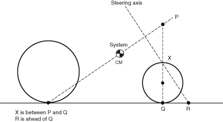
Figure 8.13
Geometric stability requirement for negative turns (which restricts the position of the steering axis).
In the early days of the safety bicycle, the handlebars were placed close to the cyclist, as had been traditional and necessary with high-wheelers, with their very serious pitchover problem. High-wheelers had little or no forward angling of the front fork: it would not have been practical because it would have prevented the cyclist from standing over the pedals, and would have placed the force vector from pedaling too far from the steering axis, making steering difficult. Bicycle evolution involved innumerable experiments, but the answer is most likely mundane: the fork was angled forward in order to keep the handlebars close to the cyclist, and for the front wheel to clear the feet, in spite of what intuitively would seem to be a stability reduction.
A bicycle can also exhibit oscillatory instability. (By this we do not mean shimmy, which is described later in the chapter).
Stability of Tricycles and Related Vehicles
As outlined at the beginning of this chapter, tricycles and other multitrack vehicles act very differently from bicycles in numerous ways. In fact, when bicyclists ride an upright tricycle the first time, it feels very odd, and the countersteering bicyclists unconsciously use to create lean for in-balance cornering poses additional risk on an upright tricycle of rolling over or collapsing a wheel. (Recumbent tricycles, on the other hand, do not have this problem and are easier to ride than bicycles at low speeds and when stopped or starting.) Some of the conditions for bicycle stability stated in the preceding sections no longer apply to tricycles or are reversed, as there is no lean angle to worry about, just the steering angle. For normal bicycle geometry, the wheel-flop factor tends to decenter the steering. For tricycles, however, this decentering is a cause of instability and no advantage. It becomes possible to use the wheel-flop factor to center the steering at slow speeds, as is done with the Python center-steered low racer (see panel [c] of figure 8.10).
Although stability and steering appear unproblematic for tricycles at low speeds, this is no longer the case for higher speeds, at which rollover stability and tire-related and aerodynamic yaw stabilities are not always assured. Whereas a bicycle can adjust somewhat to the rider’s swinging legs by rolling, a tricycle is not free to roll, so that the outside wheels experience periodic changes of load. In addition, poor wheel alignment and sloppy steering mechanisms are more readily apparent in riding tricycles rather than bicycles.
We cannot, for space reasons, give more than an overview of the extensive field of multitrack-vehicle stability, for which there is extensive literature, but we raise a few of the most important points in the following sections.
Rollover Stability
If the point (line) of support in figure 8.3 is taken to represent the line between contact patches of the outside wheels of a turning quadracycle, this shows the limit just when the inside wheels (not shown in the figure) become completely unweighted and the vehicle begins to roll over, when traveling at a critical speed V = (RT g μ)1/2. However, if the height of the center of mass (y in the figure) is smaller than half the width between tires (x in the figure) divided by the tire coefficient of friction μ, the vehicle will slide laterally instead of capsizing. Of course this applies only to a quadracycle with two equidistant tracks. For other configurations and tricycles, the longitudinal location of the center of mass is important, the rollover stability obviously being reduced the nearer the center of mass is to the single wheel. The criterion given is only a rough guide anyway, especially for high-center-of-mass vehicles going around sharp corners, which are easy to tip onto two wheels or to capsize completely. However, going fast on country roads rarely approaches the lateral acceleration needed to slide or capsize, and other steering instabilities may occur first. Note that μ values approaching 1.0 are achievable (doing so requires sideslip, described in chapter 6) but imply a lateral acceleration of 1 g (about 9.8 m/s2), which few riders could manage, even if they weren’t flung away first. In addition, the discussion here does not take into account beneficial road banking or adverse camber, either of which may contribute to tipping a tricycle, as may even small obstructions in the road surface. However, the coauthor extensively rode and even raced his two short-wheelbase, high-center-of-mass tricycles with very limited stability and never came even near a rollover situation or saw one occur in numerous HPV races during curves. Both authors have, however, seen several HPVs roll over after going out of control during straight-line riding.
In spite of its unlikelihood in most situations, many people riding tricycles feel a real fear of rollover in curves, and various projects feature leaning tricycles, either automatically or imitating the behavior of a bicycle, and only locking the normally free roll axis at very slow speeds. The coauthor’s 1986 tricycle, with this in mind, was designed to lean, but after a single very tottering ride, he decided to lock its roll axis permanently. As the mechanism doubled as a suspension, it rolled the wrong way in curves, but the tricycle was still perfectly rideable. Dong et al. (2014) show, especially in a very illustrative video showing their Bricycle, what may additionally be involved when trying to get a tricycle to behave as a bicycle. The student HPV Mjölnir (see Bamford et al. 2011) was a leaner, and in spite of very extensive design work, came to grief on its first run, influenced by a gust of wind. From this anecdotal evidence, it seems in practice that for tricycle riding, stability during straight-line riding and controllability in wind are more important than great rollover stability.
Tire-Related Yaw Stability
Huston, Graves, and Johnson (1983) examine straight-line tricycle stability, giving detailed calculations for what they call the “lateral stability” of tricycles and quadracycles: their ability to correct for yaw in the right direction when disturbed, and thus a prerequisite for stable straight-line riding. This ability has to do with tire properties (slip angle and cornering stiffness) and the longitudinal location of the vehicle’s center of mass. Below rather high critical speeds (starting at 25 m/s in the examples they give) nothing happens; the vehicle rolls straight. If the vehicle’s center of mass is located enough forward that the front tires are loaded more than the rear ones (i.e., forward > 50 percent of the wheelbase LWB for a quadracycle, > ⅓ LWB for a tricycle with one front wheel, and > ⅔ LWB for a tricycle with two front wheels), the critical speed is infinite, that is, the vehicle’s stability (in this respect) is always assured. If, however, the center of mass is further back, the vehicle’s stability isn’t assured, and it could spin out of control above the critical speed, which nonetheless seems high enough so as to be of minor concern for practical HPVs.
Huston, Graves, and Johnson (1983) also examine tricycle rollover stability in turns. When braking in a curve, they find it is better to have two wheels in front, because of the direction of the total force vector. For accelerating in a curve it is the opposite: two rear wheels are better.
Stability of Rear-Steered Vehicles
With the feasibility of even rear-steered bicycles having been mentioned earlier in the chapter, the design of rear-steered tricycles should be easy. Indeed, the coauthor has seen at least one design with a single steered rear wheel work perfectly from the start. The advantage of this configuration for an HPV is the possibility of a simpler, narrower fairing. Of course, as with most boats, which are almost all rear-steered, care must be taken to always keep enough lateral distance to accommodate the stern, which swings out sideways during turns.
However, rear steering involves instabilities in yaw (oscillations) that are not a problem in front steering. John Whitehead (1990) discusses these and presents some solutions, such as adding a steering damper or active control elements. He lists numerous previous articles on rear steering.
Aerodynamic Roll and Yaw Stability
While steady winds are no great danger to bicycles and many HPVs, which indeed can be sailed, such winds are rare on most roads, which are lined with buildings or plants, giving rise to turbulence. Even on clear roads with steady winds, other vehicles, notably trucks, can cause severe gusting. It is thus a clear design goal for bicycles and HPVs, as discussed in chapter 5, to minimize their sensitivity to gusting.
Shimmy
Shimmy is an unnerving bicycle instability that can sometimes cause an inexperienced rider to crash. When a bicycle undergoes shimmy, the steering oscillates right and left several times per second, with growing amplitude. Similar wheel vibrations are well known in airplane nose wheels, wheelchair and shopping-cart casters (castor flutter), and motorcycles (in which a violent occurrence of shimmy has been called a “tank slapper”). Wikipedia refers to all of these phenomena as “speed wobble.” A similar “trailer-wobble” effect can occur with trailers and also with two-wheeled cycle trailers, at a lower frequency. Particularly bad wobble is incurred in strings of trailers, although it is brought about by weaving (repeated yawing), described in chapter 10.
Before outlining an explanation for shimmy, it is worth considering what to do if it happens. Shimmy presents a danger when a cyclist panics and attempts actively to fight the shimmy by applying countertorque to the bicycle’s handlebars. Because the shimmy frequency is so high, the muscular response occurs too late, possibly accelerating the handlebars when they are already well on their way to the other side and increasing the oscillation. As long as the cyclist does not compound the problem through active intervention, any of several different methods seems to stop the oscillation at once:
- • Reducing weight on the saddle (by standing slightly) deprives the vibrating system of a key restraint and adds considerable damping.
- • Clamping the top tube of the frame between the rider’s knees tremendously alters the vibrating mass and also adds damping.
- • Lightly using the hands in a passive “resisting” or “motion-reducing” mode also increases damping.
Shimmy Theory
No-hands shimmy appears at a critical speed and grows to a final steady amplitude at any higher speed, with greater amplitudes for greater speeds. The frequency of shimmy is relatively unaffected by speed, as it is mainly a resonance effect. The frame of a bicycle, its fork, its wheels and its tires together with their “connections” to the ground, through their spring rates and masses and the large but loosely connected mass of the rider, form a strongly damped oscillator. Even before the shimmy is noticeable at the bicycle’s handlebars, strong oscillations can be initiated and felt by striking the front of the bicycle laterally while moving. The higher the riding speed, the longer these oscillations take to disappear, and eventually they may not disappear and may develop into a severe shimmy.
Contributing causes of bicycle shimmy can include an untrue wheel, a flexible frame or fork, loose bearings, or gyroscopic effects. Although these factors can help initiate or worsen shimmy, they are clearly not essential to the phenomenon. A key bit of evidence for this conclusion is the constancy of shimmy frequency at different bicycle speeds. In contrast to this constancy, an untrue wheel will create a steering disturbance once each wheel revolution, and the gyroscopic precession of a rotating wheel involves wobbling twice per revolution. Loose bearings, on the other hand, can induce shimmy even in wheels that are supposed to be fixed, for example, in shoddily manufactured three-wheeled microscooters.
Shimmy is a self-excited oscillation: there is no alternating force turning the bicycle’s handlebars back and forth except that generated by their motion. In instances of shimmy, the equation of motion shows a negative number for vibration damping, causing vibrations to grow rather than decay. The vibration energy is provided by the moving bicycle.
It is not our intention here to present a detailed dynamic analysis of shimmy, and indeed many aspects of the phenomenon remain in question. But it is both appropriate and feasible to present a simple system with bicycle-like features and explain how shimmy arises in the case of that system.
A castered wheel (like the front wheel of a bicycle, which is physically being towed if it has positive trail), or more generally, any rolling system with trail, such as a trailer, is capable of surprising energy interchanges with the unit that is towing it. In a situation in which the connecting hitch (or pivot axis) oscillates back and forth laterally, details of the distribution of its mass affect the side force it imposes on the ground. Because of the trailer’s angular deviation from the straight-line path of the towing vehicle, the trailer wheel’s side force on the ground has a fore-aft component that will either propel the towing vehicle (as does the tail of a fish) or retard it. Imagine a person sitting at the back of a pickup truck that drives along a straight road, and imagine that the person is holding a trailer hitch and swinging it side to side to make the trailer follow a sinusoidal path. If the result is to propel the truck forward (i.e., do work on the truck), then the side-to-side motion will require effort (power) from the person moving it. On the other hand, if the result is to retard the truck, power from the truck’s engine will flow into the person’s hand, and the hitch will try to “run away” to either side.
A very simple distribution of mass that is seen to pump energy into a vehicle hitch can be represented by a large polar moment of inertia centered at the hitch’s pivot axis. If the system is traveling forward fast enough that the hitch length is far smaller than a wavelength of the oscillation on the road surface, then the angle of the trailer towbar is essentially aligned with the path of the wheels. It can be seen that the rotation rate of the trailer is maximum rightward at the far left crest of the oscillation and maximum leftward at the far right crest. Maximum angular acceleration occurs as the trailer crosses the center line of the oscillation. What is important is that the force required to cause angular acceleration is opposite to the hitch velocity: as the hitch moves from left to right, the force of the hand holding the hitch is directed to the left. In other words, the trailer pumps power into the arm of the person holding it, trying to increase the speed of its lateral motion in both directions, right and left.
Given that a towed wheel (or trailer) with appropriate inertial properties is capable of pumping energy into lateral oscillation, such oscillations are to be expected. When energy-absorbing devices (dampers) are present, it is to be expected that a higher speed must be attained before the power delivered at the hitch can overcome the damping tendencies. Figure 8.14 shows a simple system analogous in several ways to a bicycle’s front end viewed from the side and from above. The system has the following elements:
- • A wheel or contact point towed a trailing distance (LMT) behind a hitch point (analogous to the front-wheel contact point’s being towed behind a “hitch point” low on the steering axis).
- • A significant polar moment of inertia (IZZ) of the towed wheel: a conventional bicycle wheel has much of its mass quite far away in comparison to the trail.

Figure 8.14
Simple shimmy model (trailer oscillates because of motion of ground): (a) side view; (b) top view of simpler model.
- • The mass (m) of the bicycle head-tube area, whose lateral inertia force is transmitted simultaneously to the steering axis (or hitch) through a spring with stiffness (k1) and to the rider through a spring with stiffness (k2).
- • The rider’s mass, much greater than that of the head-tube area, is assumed not to move laterally during the vibration. If the head-tube-area mass is moved laterally while the wheel is not permitted to steer, k1 and k2 can be represented by a composite stiffness (k), derived mainly from the torsional flexibility of the frame, including forks.
- • A damper c in series with k to represent the energy-absorbing connection between the frame and rider (i.e., slip at the bicycle’s saddle). A firm connection is modeled by a large value of c.
In this basic system, shimmy is predicted when velocity exceeds V = k LMT/c (1 + IZZ/m L2MT), or approximately V > k IZZ/(m c LMT).
This relationship implies that it is important to keep stiffness high, damping constant low, head-area mass low, and mechanical trail either much less, or much greater, than (IZZ/m)1/2. The great surprise in the relationship is the apparent value of increasing IZZ, which presumably helps by reducing the amplitude of steering excursion. The frequency (in radians per second) is ω = (k/m[1 + {m L2MT/IZZ}])1/2, identical to the oscillation frequency of the system at rest, as long as the energy dissipation is not too great (i.e., as long as the value for c is large—see later discussion).
This model fails to include tire sideslip or such known problems as flexibly mounted rear luggage. But it agrees with the following observations and research by Jim Papadopoulos and others:
- • If a bicycle’s saddle is restrained by pressing it against a door jamb, the head tube has a clearly defined lateral resonance at several cycles per second.
- • Experimental data by Magnani et al. (2013) support the conjecture that shimmy while riding occurs essentially at this same frequency, which is usually between 5 and 10 Hz and at accelerations of 5–10 g.
- • Shimmy can be sustained at widely different speeds depending on the firmness of the rider’s connection to the saddle (denoted by c in the foregoing discussion). By reducing saddle pressure, shimmy onset speed can be raised above 17 m/s. Conversely, by increasing pressure and lateral firmness (by exerting upward pedal forces and contracting the muscles of the buttocks), it is possible to sustain shimmy at 5.5 m/s.
No-hands shimmy experiments have found that slightly exceeding the speed at which the onset of shimmy occurs brings about sustained oscillations at a medium amplitude. Higher speeds clearly increase the steady amplitude, but not dramatically. Unfortunately, it is not possible to use this model to predict the speed at which the onset of shimmy will occur, because c is an unknown quantity. The best that can be done is to use the onset observations given earlier to determine the range of c. Taking m as 1 kg and k as 1,000 N/m to yield a reasonable static frequency, guessing that LMT was 40 mm for the bicycle ridden in the experiments, and taking Izz for the wheel as half of mass times radius squared, or (1 kg)(0.35 m)2/2, suggests c values from 260 kg/s (sitting firmly) to 70 kg/s (sitting very relaxedly).
The latest work by Tomiati et al. (2017) includes computer simulations that do include tire sideslip and support the foregoing analysis. They show that the main elements that contribute to the rise of oscillations are the lateral compliance of the bicycle’s frame and the tires’ deformation.
To summarize, bicycle shimmy vibrations depend on the combination of elastic flexibility with inadequate damping. With foreknowledge of the shimmy phenomenon, a rider can generally learn to provide adequate damping to prevent shimmy or arrest it when it occurs.
References
Almujahed, Aamer, Jason Deweese, Linh Duong, and Joel Potter. 2009. “Auto-Balanced Robotic Bicycle (ABRB).” ECE-492/3 Senior Design Project. Electrical and Computer Engineering Department, Volgenau School of Engineering, George Mason University, Fairfax, VA. https://ece.gmu.edu/sites/ece/files/S-09-ABRB_0.pdf.
Archibald, Mark. 2016. Design of Human-Powered Vehicles. New York: ASME Press.
Åström, K. J., R. E. Klein, and A. Lennartsson. 2005. “Bicycle Dynamics and Control.” IEEE Control Systems Magazine 25, no. 4: 26–47. http://lucris.lub.lu.se/ws/files/4692388/625565.pdf.
Bamford, Tad, Ben Higgins, Neal Pang, Chris Schultz, and Aaron Stanton. 2011. “2011 Human Powered Vehicle: Mjölnir.” ME 493 Final Report, Portland State University Mechanical Engineering Department, Portland, OR. http://web.cecs.pdx.edu/~far/Past Capstone Projects/2011/HPV/2011 ME 493 Human Powered Vehicle Design Report.pdf.
Davol, A., and F. Owen. 2007. “Model of a Bicycle from Handling Qualities Considerations.” ME 441—Single-Track Design (course web page). California Polytechnic State University, San Luis Obispo. https://www.calpoly.edu/~fowen/me441/index.html.
De Jong, P. H. 2017. “Rear Wheel Steer Bikes: Unconventional Stable Bicycle.” Master’s thesis, Delft University of Technology, Delft, Netherlands. http://resolver.tudelft.nl/uuid:76f67586-ab15-4c85-9841-544259b3be82 (embargoed until February 24, 2022).
Dong, O., C. Graham, A. Grewal, C. Parrucci, and A. Ruina. 2014. “The Bricycle: A Bicycle in Zero Gravity Can Be Balanced or Steered but Not Both.” Vehicle System Dynamics 52, no. 12: 1681–1694. http://ruina.tam.cornell.edu/research/topics/bicycle_mechanics/brike_paper23-proof_corrections.pdf and https://www.youtube.com/watch?v=rNQdSfgJDNM.
Dressel, Andrew. 2015. “Benchmarking a Fully Non-Linear Bicycle Model with JBike6.” Cornell University, Ithaca, NY. http://ruina.tam.cornell.edu/research/topics/bicycle_mechanics/JBike6_web_folder/JBike6_Benchmarking.htm.
Forester, John. 2012. Effective Cycling. 7th ed. Cambridge, MA: MIT Press.
Hand, Richard Scott. 1988. “Comparisons and Stability Analysis of Linearized Equations of Motion for a Basic Bicycle Model.” MS thesis, Cornell University, Ithaca, NY. http://ruina.tam.cornell.edu/research/topics/bicycle_mechanics/comparisons_stability_analysis.pdf.
Harter, Jim. 1984. Transportation: A Pictorial Archive from Nineteenth-Century Sources; 525 Copyright-Free Illustrations Selected by Jim Harter. New York: Dover.
Huston, J. C., B. J. Graves, and D. B. Johnson. 1983. “Three Wheeled Vehicle Dynamics.” In Proceedings of the Second International HPV Scientific Symposium, ed. Allan Abbott, 123–135. San Luis Obispo, CA: International Human Powered Vehicle Association.
Jones, D. E. H. 1970. “The Stability of the Bicycle.” Physics Today (April): 34–40. http://www.phys.lsu.edu/faculty/gonzalez/Teaching/Phys7221/vol59no9p51_56.pdf.
Kooijman, J. D. G., J. P. Meijaard, Jim M. Papadopoulos, Andy Ruina, and A. L. Schwab. 2011. “A Bicycle Can Be Self-Stable without Gyroscopic or Caster Effects.” Science 332, no. 6027: 339–342. http://bicycle.tudelft.nl/stablebicycle/StableBicyclev34Revised.pdf.
Magnani, Gianantonio, Nicola Maria Ceriani, and Jim Papdopoulos. 2013. “On-Road Measurements of High Speed Bicycle Shimmy, and Comparison to Structural Resonance.” In 2013 International Conference on Mechatronics (ICM), 400–405. https://www.doi.org/10.1109/ICMECH.2013.6518570.
Olsen, John, and Jim Papadopoulos. 1988. “Bicycle Dynamics—The Meaning behind the Math.” Bike Tech (December). http://ruina.tam.cornell.edu/research/topics/bicycle_mechanics/bicycle_dynamics.pdf.
Papadopoulos, Jim. 1987. “Bicycle Steering Dynamics and Self-Stability: A Summary Report of Work in Progress.” Cornell Bicycle Project report, December 15. http://ruina.tam.cornell.edu/research/topics/bicycle_mechanics/bicycle_steering.pdf.
Patterson, William B. 1998. “Single-Track Vehicle Dynamics.” In Proceedings of the Third European Seminar on Velomobile Design, Roskilde, Denmark, August 5. https://velomobileseminars.online.
Python. 2018. “Frame Geometry.” python (website). http://www.python-lowracer.de/geometry.html.
Rohmert, Walter, and Stefan Gloger. 1993. “The Test-Vehicle MULTILAB and Its New Front-Wheel Geometry: Less Interference of Hells and Front Wheel.” In Proceedings of the First European Seminar on Velomobile Design, Technical University of Denmark, Kongens Lyngby, July 8. https://velomobileseminars.online.
Rohmert, Walter, and Stefan Gloger. 1994. “Evaluation of the Handling Characteristics of a Human Powered Vehicle with a Mirror-Symmetric Front-Wheel Geometry.”
Roland, R. D. 1973. “Computer Simulation of Bicycle Dynamics.” In ASME Conference on Mechanics and Sports, 35–83. New York: American Society of Mechanical Engineers.
Ruina, Andy. 2014. “Bicycle Mechanics and Dynamics—Papers.” Cornell University, Ithaca, NY. http://ruina.tam.cornell.edu/research/topics/bicycle_mechanics/papers.html.
Schnieders, Jürgen, and Thomas Senkel. 1994. “Recumbents with Rear Wheel Steering.” In Safety and Design: Second European Seminar on Velomobiles/HPV, Laupen Castle, Switzerland, August 25, 1994. https://velomobileseminars.online.
Schwab, Arend L. 2009. “History of Bicycle Steer and Dynamics Equations Delft University of Technology, Delft, Netherlands. http://bicycle.tudelft.nl/schwab/Bicycle/BicycleHistoryReview/.
Schwab, Arend L. 2017. “Bicycle Dynamics.” Delft University of Technology, Delft, Netherlands. http://bicycle.tudelft.nl/schwab/Bicycle/.
Schwab, Arend L., and J. D. G. Kooijman. 2014. “Balance and Control of a Rear-Wheel Steered Speed-Record Recumbent Bicycle” (paper presented at the 10th Conference of the International Sports Engineering Association, Sheffield, UK). Procedia Engineering 72: 459–464. https://repository.tudelft.nl/islandora/object/uuid:57f85414-fe2d-4e83-a683-142f011ede96/datastream/OBJ/download.
Schwab, Arend, and J. P. Meijaard. 2013. “A Review on Bicycle Dynamics and Rider Control.” Vehicle System Dynamics 51, no. 7 (July). https://www.researchgate.net/publication/263686076_A_review_on_bicycle_dynamics_and_rider_control.
Sharp, Archibald. 1896. Bicycles and Tricycles. London: Longmans, Green. Reprint, Cambridge, MA: MIT Press, 1977.
Society of Automotive Engineers, International Automotive Engineering Congress and Exposition. 1978. “Motorcycle Dynamics and Rider Control.” Paper no. SP-428, Society of Automotive Engineers, Warrendale, PA.
Society of Automotive Engineers, International Automotive Engineering Congress and Exposition. 1979. “Dynamics of Wheeled Recreational Vehicles.” Paper no. SP-443, Society of Automotive Engineers, Warrendale, PA.
Tomiati, Nicolò, Ginantonio Magnani, Bruno Scaglioni, and Gianne Ferretti. 2018. “Model Based Analysis of Shimmy in a Racing Bicycle.” Paper presented at the 12th International Modelica Conference, Prague, May. https://www.researchgate.net/publication/316990951_Model_Based_Analysis_of_Shimmy_in_a_Racing_Bicycle.
Whitehead, John C. 1990. “Rear-Wheel-Steering Basics.” Human Power 8, no. 4 (Winter): 9–12. http://www.ihpva.org/HParchive/PDF/28-v8n4-1990.pdf.