10
Special Human-Powered Machines
Introduction
Human-powered vehicles include not just bicycles and vehicles with more or fewer than two wheels, but also boats, airplanes, amphibious vehicles, and so forth. It is doubtful whether devices such as sleds, skis, or even shoes can be called HPVs, but the wider term human-powered mobility surely covers these, and “human powered” can also be applied to machines and even tools in everyday use.
This chapter includes examples of human-powered machines from the last edition of this book that would seem outdated given the progress expected then. Although some of these examples no longer exist, we found ourselves still impressed with the range of devices that we had reviewed then and simultaneously disappointed at the few significant developments that have been produced since then. Therefore we have retained some that are still “best of class” or unique, either leaving material as previously described or by making comments to indicate those changes about which we have information. Our aim is to expand readers’ experience and perhaps to make them want to use, or even to design and make, some interesting human-powered devices in addition to bicycles.
People in the developed world who choose to bicycle generally do so for reasons connected with their own health and well-being and that of the region in which they live and perhaps out of concern for the earth as a whole. There are rather similar, but more limited, choices that such people can make for mowing grass and clearing snow, for example, and for recreational boating. The role of human power in the modern world of electric pepper grinders and soap dispensers is, alas, declining. Although we are engaged in some advocacy for human power in this chapter, we are not recommending that everybody cycle long distances or that human power should be used to clear snow from a supermarket parking lot or to cut the grass of a golf course. However, even in large countries like the United States, more than half the daily person-trips by automobile are of less than 8 km (5 mi), a distance most people can easily cover on a bicycle. Likewise, most lawns and driveways are of sizes that can easily be handled by human-powered devices. The past enthusiasm for reducing what has been characterized as “back-breaking” labor through the incorporation of gasoline-engine- and electric-motor-powered devices has led to an almost total neglect of efforts to improve human-powered tools. In consequence, there is today an unfair competition between highly developed modern electric devices, for example, and manual ones that have not been sensibly improved for a hundred years. Perhaps we need a new series of prizes like the Kremer (see discussion later in the chapter) for specific achievements in human-powered tools. For example, we have never heard of a human-powered leaf blower, but surely one could be developed, as the efficiency of the usual motorized and very noisy devices is extremely low.
We have chosen to discuss in this chapter two examples of human-powered tools and a series of interesting vehicles (other than standard bicycles) for use on land, on and under water, and in the air. Each example deserves several pages of description and discussion, but the available space will not permit such an extensive treatment. We have selected some interesting features in each case and hope that readers wanting more information will examine the references cited to find out all they want to know.
Human-Powered Lawn Mowers
The first three editions of this book included descriptions of various pedaled lawn mowers. Since then many more have been built, including an attractive one by Herslow (2011) as a degree project in design. However, we suspect that there will be no breakthrough in this field for a simple reason: except on very hard turf, overcoming the rolling resistance of a person on a pedal mower requires greater effort than walking, and this is additional to the effort needed to operate the cutting device. The energy required to pedal a machine across soft ground is so great that the only way in which pedaling a mower would be superior to pushing it would be for the pedaler to be either stationary or moving slowly, while the cutter covers a wide swath area at a higher rate of speed (in fact, rather like scything described in the next section). Also, some conventional reel-type push mowers have become very efficient through the use of extremely accurately made reels, which can be adjusted so as not to contact the mower’s fixed knife edge at all (typical gap: 0.1 mm) and still cut grass. The effort needed to cut most lawns with such mowers is initially very small. (Unfortunately, the precision parts get worn or damaged eventually and without refurbishment or replacement either no longer cut well or cause more resistance.) For long grass, a so-called sickle bar has to be used. We suspect that those sold in the early twentieth century (see figure 10.1) had a relatively high degree of friction and are therefore no longer sold.
However, human-powered grass cutting with the traditional scythe has undergone a minor revival, and so we mention it here. The website of the Scythe Association (scytheassociation.org) offers an enormous number of recent resources. Scything is effective for cutting grass if at least two of the following three are available:

Figure 10.1
Sickle-bar push lawn mower. (Photo by Ora E. Smith.)
- 1. A sharp blade set at the correct angle
- 2. Skill or experience
- 3. Strength or good physique
The main point is the first one, and the main problem from a technical perspective is the sharp blade. Scythers generally hone their blades every few minutes and regularly have to peen them, say, after 12 h of use. If science could find a suitable ever-sharp material or at least a handy peening machine, scything could be more widespread. However, if the first two points can be satisfied, scything is quite efficient, and if all three points, fast as well. Champion scythers take less than 2 min to mow 25 m2; those less strong and skillful typically need 8 min.
Human-Powered Snow Removers
The use of snow shovels at the first snowfall of the winter always seems to produce reports of heart attacks. Shoveling snow is a heavy task involving the use of the muscles of the arms and back and of having the back bent uncomfortably. It would be more efficacious and put less stress on the body to use instead the big muscles of the legs and to have a more natural posture. More than that, it would be delightful to have a small, lightweight device that, from leg operation alone, scooped up a quantity of snow and projected it in a desired direction, as one does with considerable effort using a snow shovel. Nothing like that has been on the market, or even in the patent literature, unfortunately, judging from searches carried out by the senior author and his students. Figure 10.2 shows his favorite tool for clearing snow: an old push plow purchased at a garage sale. He made and installed on the push-plow a fiberglass “blade” with a mild-steel cutting edge. He liked to demonstrate that, on the asphalt surface of his driveway (about 50 m2), he could clear snow in about half the time it took his neighbors with similar driveway areas, using their engine-powered snowblowers.
Another very useful device in this regard is a snow sled shovel, a very wide curved shovel with a double handle. Pushing this forward and adjusting it vertically, the snow is scooped up, transported, and dumped, but never needs to be lifted. Using this device, it is easy to push heavy, wet snow (too heavy for the snow plow) a considerable distance over snow, which can be built into a long ramp, before dumping it.

Figure 10.2
Dave Wilson’s push snow plow. (Photo by Ellen Wilson.)
More recently a device called Snow Wolf Shovel has come on the market that more or less combines the two devices just discussed. However, the senior author still preferred his, and the coauthor likes to keep the snow in place for skis and sleds!
Kick Scooters
Whereas the evolution of the Draisine into the bicycle is well-known, both being vehicles for normally saddle-supported persons, the evolutionary branch toward two-wheelers for standing persons is less documented. However, the US Patent Office lists hundreds of patents related to scooters (often also called coasters and rarely pedicycles) from 1920 through 1940 and beyond. The German Bundesarchiv has photographs of children using foot-propelled (kick-)scooters in Paris, Berlin, and Leipzig between 1930 and 1951 (see figure 10.3). Wikimedia Commons 2018a shows some of these and a few others, along with later scooters with relatively wide pneumatic tires from the mid-1950s onward.

Figure 10.3
Small-wheeled children’s scooters in Berlin, 1948. (Photo from Bundesarchiv, Bild 183-19000-2205, licensed CC-BY-SA 3.0.)
We remember as children such kick scooters. Their medium-sized, relatively low-pressure pneumatic tires had too much rolling resistance to make them much fun, especially after we were introduced to “real” bicycles, capable of long-distance excursions and travel in traffic, even by children. The scooters with tiny, solid-tired wheels that are common today had then already come and gone, perhaps because most road surfaces then were likely to be too rough for them to be used comfortably. In the 1980s, kickbikes were developed with almost full-sized pneumatic bicycle wheels, or at least a large front wheel. With bicycle-like rolling characteristics, they can be used off road and on many roads, can carry luggage, and today are popular for touring purposes and for exercising dogs.
A specialty was developed in the 1970s in the Democratic Republic of the Congo: long, wooden scooters called chukudus (figure 10.4). They are a widely used form of cargo transport around the city of Goma and are among the most efficient and ecological forms of land transport possible, given the situation: goods are mainly transported from the hills downward into the city, up to half a ton or so at a time, with employment for local pushers on uphill stretches. Empty, chukudus can be propelled by foot, the body supported on the nonpropulsion knee. An online search readily provides information, pictures, and videos.

Figure 10.4
Man using a chukudu in North Kivu, Democratic Republic of the Congo. (Photo by Neil Palmer [CIAT], licensed CC-BY-SA-2.0.)
The children’s scooters and large-wheeled kickbikes described in the preceding paragraphs are not very suitable for urban transportation. They are not as vehicular as bicycles on busy main roads, not very maneuverable on sidewalks and hardly unobtrusive there, and not very suitable to take easily on public transport or inside buildings. Therefore in the late 1990s, compact tiny-wheeled scooters were reintroduced and also made foldable. Unlike their predecessors with rubber tires, they had extremely hard-wearing polyurethane skate wheels, and by then riders had a wide choice of smooth sidewalks and roads on which to use them. Their quick foldability, small size and weight, high maneuverability, and low rolling resistance on smooth surfaces made them immediately popular not just with children, but also with adults, including the coauthor and his wife. This revival and the modern aluminum design is credited to Wim Ouboter, first as personal practical transport, and later as the basis of the company Micro-Mobility. Around the year 2000, sales exploded, and the scooters became quite fashionable with young urbanites. The ensuing fad was helped along by countless plagiarized copies that worked reasonably well even in cases of cheap or even shoddy designs and both helped and hindered sales of the more expensive quality brands. Recognizing this, Oubouter didn’t waste time in legal conflicts but instead kept ahead of the competition by producing new models for different user groups, as well as tricycle scooters and toys, today producing more than fifty different models. Interestingly, evolution repeats itself: from tiny solid-tired wheels, to larger solid wheels (greater usability on rougher surfaces), to small, high-resistance pneumatic and wide solid wheels (neither much fun except downhill), to medium-sized pneumatic wheels like those in the 1950s (and to saddles and power; more about these later).
Most of these two-wheelers steer, balance, and handle in a manner roughly similar to bicycles and seem even easier to use, except that the handlebars and standing platform take over the role of the saddle in allowing the rider mass to apply roll to the dynamic system. Like bicycles they work well even if distorted, loose, or otherwise decrepit. However, some alternative designs exist with certain advantages, once they are mastered. One is the Plankalkül developed by Bernhard Kirsch and Christian Marx (figure 10.5) as the ultimate street scooter suitable for “extreme shopping,” as they say, and steerable with one hand or no hands, as they show. This is achieved with a mirror-image (negative) head angle α, which makes the wheel-flop factor (described in chapter 8) center the front wheel. The Plankalkül has a joystick for holding on during kicking but can also be propelled by wedeln (oscillation) in a manner rather like what can be done with caster boards. Unfortunately, Kirsch and Marx’s project hasn’t made it to production yet, but it is well described on the Plankalkül website (bodenstaendig.de/strassensurfbrett/).
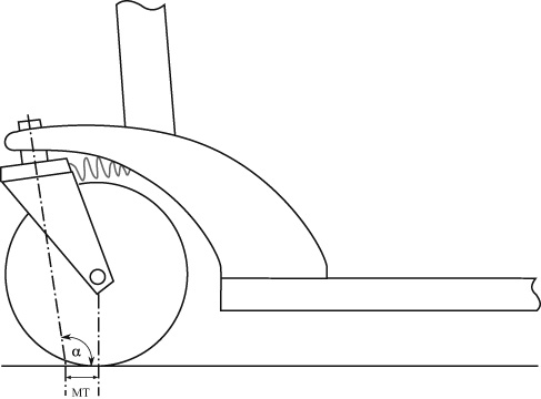
Figure 10.5
Drawing, showing head angle (α) and mechanical trail (MT), of an early model of the Plankalkül street surfer, which can be ridden with no hands by virtue of a wheel-flop-centered, castering front wheel.
Three Wheels and More
Most of the two-wheeled scooters described in the foregoing steer somewhat like bicycles, even though leaning the body works in a different way and free-handed riding is normally not possible. With the addition of a third wheel or more, steering and balancing are radically different from that of a bicycle, especially as many different configurations are possible, for example, modifications of the four-wheeled skateboard, in which putting pressure on one side of the board causes it to roll and the wheel axes to yaw, producing a turn. A single four-wheeled roller skate works much the same way, and so do many three-wheeled kickboards. Instead of the turntable of a traditional cart or cargo trike, which has a vertical axis and is directly yawed with some lever or handle, skateboards and the like have trucks on slanted axes, centered by elastomers and operated by weight shift. Theoretically their steering can be improved with Ackermann-type linkages, as discussed in Downs 2011.
Unlike countless historic designs with a single steered front wheel, newer tricycle scooters mostly have two wheels in front, with Ackermann-type linkages like those on larger vehicles, but operated by the scooter platform’s roll angle and not by a steering wheel or bar (see figure 10.6). The models for adults originally had a handle with a knob, suggesting that it was not for yawing, but rather for one-handed rolling, or simply holding on to. Models for children and even newer adult models now have a handle for holding with two hands but still work the same way.
Although they are somewhat stable at rest, steering and balancing these tricycles is less intuitive, to cyclists at least, than the same operations on two-wheelers, even for well-designed models. Unfortunately there are many ways to make these devices nearly unrideable at anything above walking speed. All that is required is a flawed geometry or too much play in linkages and bearings, which can also happen through wear even in better models. This is perhaps one reason they haven’t caught on as much as two-wheelers and four-wheelers.
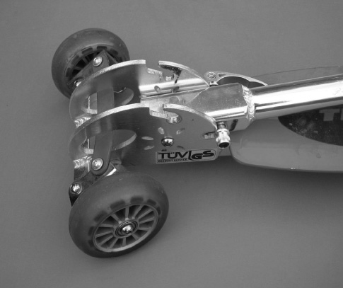
Figure 10.6
One of the coauthor’s three-wheeled kickboards, unrideable at greater than walking speed even when new, probably because of excessive play in the linkages, in spite of TÜV-“tested” sticker and the logo of a reputable brand (not shown) (both may be forged)!
Many variants with peculiar geometries can also be found, for example, three-wheeled carving scooters with two pivoting trailing arms and rear wheels, one for each leg. This allows a strong leaning effect, small turn radii, and propulsion through properly phased weight shifting and steering movements. The word carving in this context probably comes from modern types of skis and snowboards that, in turning, are strongly inclined and “carve” through the snow on their edges, in contrast to traditional skis, which are inclined less and “slide” sideways.
Loads and Luggage
Most scooters don’t have luggage racks or a provision for attaching a trailer, although both are possible. In an attempt to achieve at least a small percentage of the carrying capability of the African chukudus mentioned earlier in the chapter, two other approaches have been tried: industrial cargo scooters for warehouses and the like and trolley-type suitcases fitted out with an additional kickboard that can be folded up.
Models of the first type are, for example, designed for loads additional to the rider of about 50 kg and 70 L (Nimble two-wheeler), 90 kg and 150 L (Monark three-wheeled transport scooter, one front wheel steered, one front wheel castering, rear wheel fixed), or 120 kg and 190 L (Nimble five-wheeler = two middle fixed, two castering front, one steering rear).
The second type are typically for about 25 kg or 25 L and can be used not just in airports and railway stations, but also on sidewalks and minor roads. There are several makes. The coauthor bought two of the first ones available. A pioneer was the nicely named and designed Scootcase in 2001 by Robert Wohlfahrt, who has since gone out of business. Wohlfahrt found a clever solution for the requirement that such scooter suitcases must be able to roll in the opposite direction when scooted to that when trailed by the handle, like any two-wheeler suitcase trolley or hand-trailer. When the suitcase is used in the tricycle-scooter mode, the two front wheels have axle journals freed for steering by weight shift. When the platform is folded up, it automatically fixes the two wheels so that they don’t shimmy when the suitcase is used as a trolley (with reversed trail). Unfortunately the Scootcase was very difficult to ride in a straight line, the mechanism not technically mature or well engineered.
About ten years later, the much larger companies Micro-Mobility and Samsonite introduced their Micro Luggage (see figure 10.7), which today still gets good press and customer reviews and is produced in several similar variants. The coauthor’s model came with four wheels. Two are on a front turntable-like axle, but attached with an angled axle to the case with just enough flexibility to yaw a bit when the device is forced to roll, like a very stiff skateboard truck, and two as a fixed double on the rider’s rear folding platform. The Micro Luggage rides nicely in a straight line, but only under about 3 m/s, above which it starts to shimmy. The owner’s manual states, often with double exclamation marks: “Maximum speed: 10 km/h. Not a toy, not for children. Not for down slopes (braking not assured). Not for both feet on the board. Not for wet surfaces.” Also, only a very large turning radius is possible. After the coauthor inquired about this, Micro sent him a “carving” wheel as replacement for the double rear wheel. This has a clever castering axle inside, held elastically but very stiffly, that produces about 40 mm trail when mounted with the caster axis at −45°. This improves the maneuverability at the cost of a considerably higher rolling resistance. As a suitcase the Micro Luggage is of good quality, but rather small, only 10 L for rectangular things like file folders and 25 L for deformable things like clothes or small items. The coauthor pretested a new model now on sale. It has a larger capacity (33 L) and a very small turning radius but in the test started to shimmy severely at about running speed. This problem needed to be solved and no doubt has been.
Interestingly, the first concept for such a design was probably the Caseboard, proposed by two Swiss design students, Christof Hindermann and Jérôme Gesaga, in 1999. They offered it to Samsonite without success, but this may have caused Samsonite to contact Micro-Mobility ten years later in order to develop the Micro Luggage, according to Glanzmann (2011), after the Caseboard trademark had expired. The coauthor, inspired by Scootcase, has also experimented with suitcase scooters, which he calls TranSportIV(e) (Schmidt 2008).

Figure 10.7
Micro Luggage in typical environment, with special rear “carving” wheel.
A newer make of luggage scooter is the Olaf-Scooter, which on video appears to handle well and is available with cases up to 40 L.
Saddles and Power
In China there have been many millions of slow electric scooters on the road for years, equipped with saddles. In the United States and Europe, e-scooters are available that look almost like unmotorized kick scooters, although they are much heavier. They are becoming popular as a result of new legislation allowing legal use, and huge quantities are today available for rent (see chapter 11). Many are cheap and shoddy, but some are more expensive, of good quality and equipped with lights, disk brakes, lithium-based batteries, and a powerful multipole motor inside the rear wheel. Whether they can be legally used on public roads depends on local legislation and the scooter’s configuration and speed. In Switzerland and Germany, for example, legal models can be used as a “bicycle,” at least on cycle paths and minor roads at speeds up to 20 km/h using only the motor (Federal Ministry of Justice 2019). Although many models require an initial foot-kick to be able to switch on the motor (6 km/h minimal speed in Germany), they aren’t hybrid vehicles like the pedelecs described in this book and keep going without further human power.
The coauthor includes in Schmidt 2008 the idea for an assist system controlled by sensors measuring the true acceleration (derivative of speed) and the apparent acceleration, allowing the calculation of slope and controlling the motor with any desired kick-augmentation characteristic. In 2018 he was able to ride such a kick-controlled e-scooter prototype at Micro Mobility and is convinced that a forced deceleration of about 0.05 m/s2, thus requiring regular kicks to keep going, would be much superior in regard to fun and safety to the fully powered e-scooter models that authorities have now allowed. Micro Mobility (2019) now sells such models fitted with what it calls “motion-control steering.” A short video explains the function. Slope is compensated for, and after 10 s of operation, a renewed kick or a sharp hip movement is required to keep the motor going. This raises the legally permissible motorized speed in Switzerland to 25 km/h, a strong incentive for the use of at least some human power.
We haven’t seen any nonmotorized scooters with saddles, but Paul Schöndorf, who formerly conducted HPV research at Cologne University, fitted a folding scooter with a saddle in such a way that it can still fold (figure 10.8). He says he can scoot much more easily and farther while seated than while standing. (Kick-scooting involves moving one’s entire body weight unproductively a few inches up and down for every push.) Schöndorf’s device is in effect a very short and maneuverable Draisine. He finds it better to use only one leg for propulsion as if still standing and suspects that early Draisine riders did this also, as it results in a better connection from the rider’s body to the vehicle without the rider’s having to grip tightly with the hands. The unobtrusive vehicle with saddle can also be taken into crowded places and offers a weary person a seat almost anywhere.
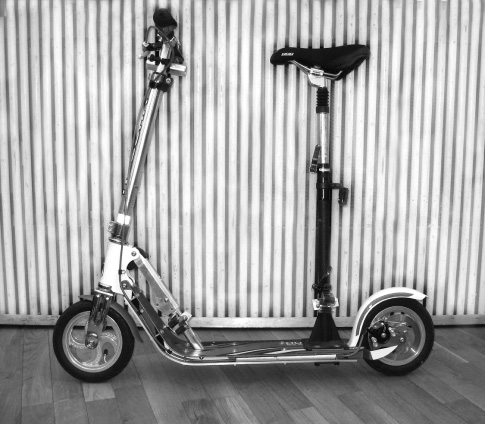
Figure 10.8
Paul Schöndorf’s scooter with saddle (still foldable).
Safety
Although kick scooters seem dangerous and generate a large number of accidents, fatalities involving such scooters appear rare (although increasing in the United States; see the injury statistics in CPSC 2019), and at least in Switzerland, the home of the modern kick scooters, a great many children are allowed to use them, even on (minor) roads with traffic, to get to school before they are old enough to bicycle.
The quality of many kick scooter models is questionable, in spite of “tested” stickers. Some of their marginal features are inherent, especially the poor braking and steering capability in wet weather. (It is still possible, but requires practice, to brake adequately [briefly] by putting one’s full weight on the rear brake shoe.) It may be that specifically the perceived insecurity involved in riding a kick scooter leads most people to go no faster than they are willing to hit the road and motorists to take more care than with cyclists and pedestrians. Nonfolding robust models with more ground clearance are also available for sporting use in half-pipes and the like.
Human-Powered Vehicles for People with Disabilities
A great many special HPVs have been constructed to allow humans with disabilities to participate in cycle racing and general sports and to facilitate everyday transport. The adaptations include slight adaptations and hand cranks in lieu of foot pedals, and there are in addition completely custom-made constructions. Figure 10.9 shows a tricycle (Varna I) designed by George Georgiev especially for Daniel Wesley, a world skiing champion and Olympic gold medalist and a double amputee. Figure 10.10 shows an arm-powered, unfaired low recumbent being used in a road race. Amphibious boats are available that allow fit paraplegics to transfer from a wheelchair and enter the water safely. Hand-crank or hybrid add-ons or even half-bicycles (for a second person) can be fitted to wheelchairs.
A related field is that of electrical-assist devices. One method, uniquely for people with spinal-cord injuries, uses functional electrical stimulation to get paralyzed muscles to contract and enable, for example, paraplegics to power tricycles with their legs (see Technical University Berlin 2009 and Inria 2018). (Others are working on powered exoskeletons for rehabilitation and even for able-bodied people; see Marinov 2016.) A more frequent usage is assist-motors fitted to wheelchairs and special-needs bikes or trikes. Some firms specialize in fitting these as human-power assist instead of simple fingertip-controlled traction (see, e.g., Van Raam 2018 and Rio Mobility 2018).
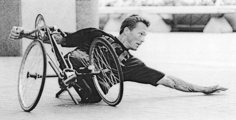
Figure 10.9
Varna I tricycle, designed by George Georgiev for Daniel Wesley. (Courtesy of George Georgiev.)
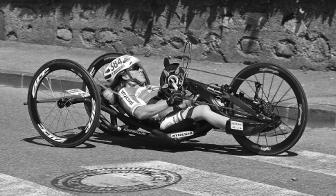
Figure 10.10
Arm-powered recumbent in a paracycling race circa 2013. (Photo by Pixabay user Mzter.)
Human-Powered Snow and Ice Vehicles
Skis and sleds may have been the first practical human-powered land vehicles. Today, the most versatile skis from a locomotion point of view are classic cross-country types: narrow and long enough to offer minimal resistance even in deep snow, a small “one-way” traction surface (skins, scales, or sticky wax) for resistance in the backward direction, boots free to pivot at the toe, and poles for aiding propulsion and balance. More modern skate-skis are faster but require a wide, smooth snow surface that generally must be prepared by machines. Skis and boots for mountain use are heavier and require the fitting of skins for going uphill. A new invention, Crossblades, functions like snowshoes uphill yet can be quickly transformed into miniskis for skiing downhill.
Leaving aside fat-tired or studded bicycles on snow or ice, there are a number of other types of snow and ice bikes available. Fitting skis instead of wheels on a bicycle-type frame results in a ski bob, which is generally used with tiny skis and claws on the feet for additional balance and braking. A ski bob is more or less a pure downhill device and is often fitted with suspension to avoid excessively jarring the rider’s spine. More bicycle-like and transportation oriented is a Swiss specialty called a Velogemel (figure 10.11), invented in 1911 by the carpenter Christian Bühlmann for getting around more easily with his slight handicap. Made almost entirely of wood except for the steel surfaces under the roughly 20 mm wide, slightly concave runners, it steers like a coasting bicycle downhill, with the feet resting on stubs or used for braking. On flat surfaces, they can also be used for propulsion as with a Draisine. On steep uphill ground, the narrow and light (~7 kg) Velogemel is easily pushed or shouldered. As today even ski resorts tend to remove all snow from roads, Velogemels (like sleds and skis as well) can often no longer be used for local transport, only for sport and tourism. They can be rented (at the railway station), raced, and purchased in Grindelwald, Switzerland, where they are still manufactured.
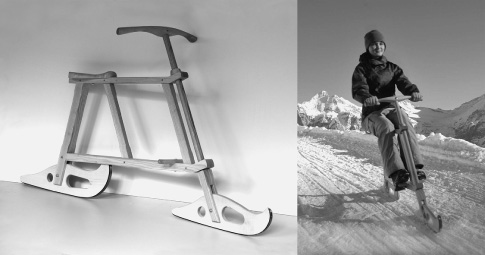
Figure 10.11
Velogemel “bicycle sled” with pivoting runners, static and leaning in curve. (Courtesy of Holzkreation Schmid AG [velogemel.ch].)
Human-Powered Speed Machines
A great many speed records have been set in HPVs (some recent ones are noted in chapter 3), and space is insufficient here to pay tribute to them. However, we would like to make space for a commercial of sorts. In the second edition of this book, the senior author applied the methods recommended in earlier chapters to forecast that the maximum speed of a streamlined HPV pedaled by a top athlete through a measured 200 m would be 65.4 mph (29.25 m/s) (Whitt and Wilson 1982). He was subsequently very proud that this transpired with the Easy Racer Gold Rush (designed and built by Gardner Martin), at 65.5 mph in 1986. This apparently accurate forecast held for six years, when it was proven pessimistic, as the Cheetah fully faired recumbent bicycle (figure 10.12), designed and built by a team from the University of California, Berkeley, achieved 30.7 m/s (68.7 mph) on a high-altitude desert highway in Colorado. Nine years after the Cheetah set its record, in 2001, the Varna Diablo recumbent bicycle sped along at 36.0 m/s (80.6 mph) on a long, nearly flat asphalt road near Battle Mountain, Nevada. Second in speed at the same venue was Matt Weaver’s Kyle Edge (figure 10.13). By having the vehicle’s rider lie on his back, looking at a small monitor connected to a television camera in the vehicle’s nose, Weaver was able to design a fairing with a flow that was predominantly laminar and therefore with a low drag (see chapter 5). Panel (b) of figure 10.13 shows his speed and power versus distance. Not shown in the figure is the effect of gravity at this site: the slightly sloping run-up allowed “harvesting” of about 30 kJ potential energy, and the slope contributed up to 200 W power at maximum speed (see chapters 3 and 4). Of particular interest is the planned power level, starting at 350 W and reaching 600 W in the timed section. A successful speed record of this type has as much to do with the continuous optimization of the human power level during the run-up as with the technical optimization of the vehicle. The higher speeds achieved today at the Battle Mountain site reflect not only vehicular improvement, but also experience and practice in this human-power-level optimization. The present record at this site, by the Aerovelo Eta, is over 40 m/s (89.6 mph, 144 km/h).
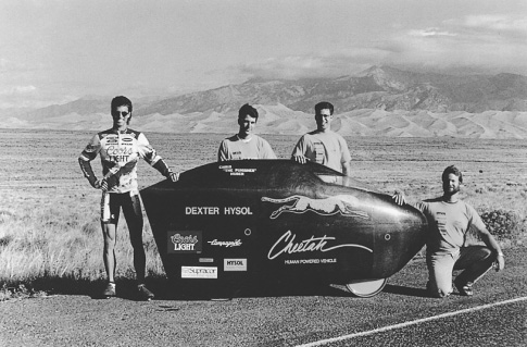
Figure 10.12
Cheetah fully faired recumbent bicycle.
Human-Powered Rail Cycles
During and after the time when railroads were being built, railcars—generally worked by hand levers (pump trolleys)—were used to take workers along the rails and to inspect the track. Some rail inspection continued into modern times using especially light single-person pedaled vehicles. In some Asian countries railcars and even small trams with passengers were hand pushed, as were small mining carts everywhere. See Wikimedia Commons 2018c and its subcategories for many photos of both historic and modern vehicles and Wikimedia Commons 2018b for many more.
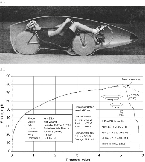
Figure 10.13
(a) Matt Weaver in half of the fairing of the Kyle Edge HPV; (b) Matt Weaver’s speed and power versus distance in his October 6, 2001, run, Battle Mountain, Nevada. (Courtesy of Matt Weaver.)
Today many tracks are in heavy use by high-speed trains and no longer suitable for such vehicles. Others are being abandoned, leaving priceless rights-of-way connecting towns across (usually) picturesque rural routes having low maximum gradients and ideal for cycling. The rails are removed from many such trails, and some are made into cycle paths. In many other cases, however, the rails remain and are available for either officially organized or clandestine (mostly illegal) sport and tourism. Traditional small rail vehicles are called handcars or draisines, even though they are technically quite different from the Draisines described in chapter 1. However, a draisine in both senses of the word was patented in 1897 and is now preserved in the Mulhouse (France) railway museum. Restricted to a single rail, it must be balanced as well as propelled with the legs, requiring special skills.
Today human-powered draisines are offered mostly for touristic use by track owners themselves. The website Railbike.de lists over a dozen sites, mainly in Germany and France, where such vehicles are available (figure 10.14). They are generally moderately heavy, with four steel wheels, and usually pedal powered by two persons, but with room for more passengers. As the lines are mostly single-track, passing involves one party lifting the vehicle entirely off the track in order to let the other one pass. Speeds are usually under 4 m/s or so, because of friction or gearing, and this is often desirable from a safety point of view. Compared to road vehicles, there is the danger of derailment and injuries from the track’s rough, sharp-edged gravel ballast. Also, the tracks sometimes cross roads, and the draisines must be able to stop in order to give way. At least one resident of the Hallig Nordstrandischmoor (a special type of North Sea island off the coast of Germany) is seen regularly using the track connecting to the mainland at Lüttmoorsiel in order to go shopping with his rail bike.
An unofficial type of adventure sport or tourism is rail biking: cycling on one rail, balanced by an outrigger to the other rail. A true single-rail bicycle without outrigger would be practical for passing other rail bikers. No easy way of balancing seems yet to have been conceived, but it would be possible by using (powered) flywheels as gyroscopes or reaction wheels (see chapter 8).

Figure 10.14
Typical tourist rail draisines at Saint-Thibéry, France, one of three Pedalorail sites (pedalorail.com). (Photo by Didier Duforest, licensed CC-BY-SA 3.0.)
Rail bikes are used mostly on remote, hardly used, or abandoned railroad tracks in North America (see Mellin 1996). Figure 10.15 shows Richard Smart’s Railcycle apparatus for converting a bicycle to a rail cycle. It steers the bicycle’s front wheel (and consequently also the rear wheel) to stay exactly on the rail and uses a lightly loaded outrigger to keep the bicycle upright, as the normal weaving motion for balancing is no longer possible (see chapter 8). The steering apparatus uses a magnet to locate itself against the inside of the rail, as the outside edge is often unavailable or clogged up. Similar devices can be built at home; plans are available on Richard Bentley’s comprehensive railbiking website (rrbike.freeservers.com), which also includes pictures, travel reports, and links to many other projects.
Human-Powered Rail Vehicle Technology
Typical rails offer a 2–3 inch (~50–75 mm) wide steel surface that is, however, slightly rounded on top and generously rounded on the edges and is often canted inward at a 1:40 angle. Typical steel wheels are conical at 1:20. Thus in normal operation there is a “point” contact, and the wheel flanges do not touch the rails. If two wheels are fixed on a common axle, they will steer themselves without using the flanges, as any lateral displacement causes a difference in the wheels’ radii and a resulting corrective torque and movement. This results in smooth steering but also, depending on the degree of freedom in yaw, some scrubbing and friction. In turns the flanges come more and more into play. In practice, however, most human-powered draisines don’t use such a common-axle system anyway and instead allow the wheels to turn independently. Some use lightweight cylindrical wheels with attached conical or vertical inside flanges that then cause friction when they touch the edge of the rail. A square inch or so (25 × 25 mm) is generally free at the rail’s inside edge for flanges or other guidance, but the rail’s outside edge is often not usable, notably at level crossings and points. This is a problem for asymmetric rail bikes with lightly built outriggers, especially as the width between tracks (e.g., 1,435 mm standard) varies, being greater in curves. Some rail bikes use guides on the outside edge that can flip up or are very short. Most rail bikes, including those used for racing, separate the vertical-load-carrying and the lateral-guidance functions completely. For the former, bicycle wheels with tires are often used or thin machined disks; for the latter, thin inclined skate wheels or even just small ball bearings, inclined or vertical. Single outriggers generally don’t need lateral guides.
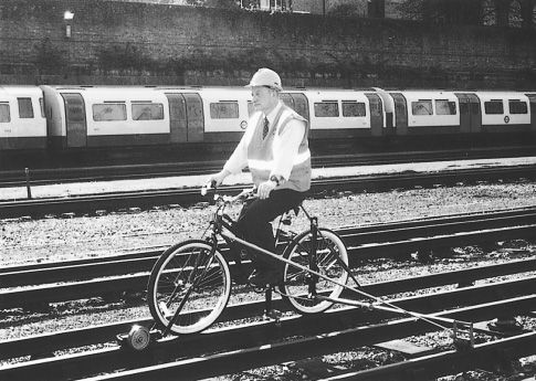
Figure 10.15
One of ten Railcycles purchased by the London Underground, used here by an engineer. (Courtesy of Richard Smart.)
A further type of rail vehicle uses a recumbent position and a full fairing. See chapter 3 for a description and picture of Charles Henry’s record-breaking faired machine Snapper (figure 3.8), which was built for officially organized 200 m rail speed trials in Laupen, Switzerland. These speed events came about because the local railway company closed the line between Laupen and Gümmenen, serving commuters with buses instead, and the coauthor wanted to “rescue” the rail connection with solar- or human-powered draisines for travelers. Of course this option was of no interest to the rail company, but its director, Erich Scheidegger, knew the line’s leisure potential and helped organize the speed events and purchased touristic draisines himself. Unfortunately, a small part of the track has been ripped up, severing the Gümmenen connection, but most of the length is still available for booked parties using the draisines. Scheidegger bought the remaining track and since his retirement runs the family business (Schienenvelo.ch) and organizes trips for up to 8,000 persons per year.
A page on the Future Bike website (futurebike.ch/page.asp?dh=2058) shows the results of the four events on the Laupen track from 1997 to 2001, along with some pictures. (The coauthor managed the slowest recorded time at 18.5 km/h with his ScootRail, a four-wheeled rail kneeboard.) At just over 70 km/h (19.46 m/s), Charles Henry achieved the fastest rail speed during the 1999 HPV World Championship (Interlaken Festival of Human Power). He and his cobuilders based Snapper’s design on that of a road machine with a 17-inch front wheel and a 20-inch rear wheel driven by a 2 × 7 transmission. Skate wheels are used on the sides of the rail under the cockpit to keep the vehicle’s wheels centered. The layout has a compact long wheelbase (1.5 m) with a single-tube chassis, on which the fairing is mounted.
The track in Laupen was, as noted previously, out of regular service, but it was well-maintained, straight, and relatively flat. The last speed trials on rail took place there in 2001. Charles Henry was a bit slower in those trials, but another rider achieved a speed of more than 70.5 km/h in Snapper, and another team led by Romeo Gridelli achieved 74.53 km/h with a rather similar vehicle and a champion rider. This may be still be the 200 m speed record—at least we are unaware of any similar events since. It could easily be bettered at another site, as the available run-up at the Laupen site is only about 1.5 km.
It has generally been believed that streamlined (faired) rail cycles should be the fastest possible HPVs. However, to achieve top speed they would probably need to have a special narrow-gauge track, perhaps of 200–300 mm, which, for a record attempt, would probably be a banked circular track of, say, 200 m diameter. This would confer on rail cycles using such a track the following advantages over pneumatic-tired bicycles on a highway:
- 1. Wheels made of steel (or of other hard material) used on steel rails would have very low rolling resistance.
- 2. The wheels would not have to be steered, so they would be mostly inside the fairing and could run in narrow gaps (thus avoiding large “pumping” losses).
- 3. Not being needed for steering, the rider’s arms could be used to add power to that delivered by the legs. An increase of 20 percent in power output could be expected for a short-duration effort. Also, the rider would not have to see ahead, if the track were circular and well protected, so that the air drag associated with a window and a heads-up position could be eliminated.
- 4. The streamlined enclosure would be better aligned with the relative airflow and steadier than that on a typical road machine, so that boundary-layer suction might be used to extend laminar flow and thereby to reduce the aerodynamic drag (see chapter 5).
This is the theory, but so far rail vehicles have been slower, not faster, than similar road vehicles. A good example is Charles Henry and his Snapper, just described. During the same week in 1999, with a similar run-up of about 1.5 km and a 200 m timed section, he achieved 81.6 km/h with Snapper as a road vehicle (on the runway of the Interlaken airport) and more than 11 km/h less as a rail vehicle in Laupen. Part of the difference is due to unequal slopes (about −0.33 percent in Laupen and −0.45 percent in Interlaken) and part to the vehicle’s outrigger and its wheel. A further reason may be that a road bicycle is free to weave very slightly with the periodic yawing moment caused by the rider’s swinging legs, but a rail cycle experiences periodic side forces that are taken up only by guides—skate wheels in this case. The similar Gridelli vehicle was also ridden by the same champion in both 1999 speed events: 72.5 km/h road and 69.0 km/h rail. This rather smaller difference is a bit surprising, as the vehicle’s rail outrigger consisted of four unfaired tubes generating considerable air drag. An unknown factor was the wind, which, although slight, wasn’t monitored closely enough to estimate its actual effect.
To sum up, human-powered rail vehicles could theoretically be faster than similar road vehicles, but only with careful optimization of all components. Up to today they have always in practice been slower.
Human-Powered All-Terrain Vehicles
All-terrain bicycles (ATBs or mountain bikes) are well known and fall outside the topic of this chapter, as do the multitrack, often artistic human-powered all-terrain vehicles that can traverse sand, mud, and water. The former are still undergoing development, spurred by competition for a still-large market and by the desire on the part of component and bicycle manufacturers to win races, in order to increase market share. The rapid developments in suspensions, gear-shifting mechanisms, disk brakes, wheels, and tires for ATBs have been beneficial to the rest of the bicycle industry, including HPVs. Derailleur transmissions and exposed chainwheels are weak points in present ATBs, and it seems probable that some of the alternative transmissions described in chapter 9 will be adopted for these bicycles. Electrically assisted ATBs have extended their attractiveness to new user groups, fat tires to new terrains. Organized downhill ATB racing is a growing activity. Improved reliability of all components is a probable outcome of further competition and development.
Human-Powered Recumbent Vehicles
Recumbent bicycles are those in which most of the rider’s weight is carried in a seat; a little on the pedals, which are out in front of the body; and virtually none on the handlebars. (On a diamond-frame [i.e., upright] bicycle, the weight is ideally divided equally among saddle, handlebars, and pedals.) Enthusiasts for recumbents (as we are) believe in this type of bicycle for commuting, touring, and its own form of racing. Only in dense city traffic does the upright bicycle seem superior with respect to overall vision and maneuverability.
As observed in chapter 8, recumbents are produced in many configurations. Some have the front wheel behind the cranks and bottom bracket, producing a short wheelbase (SWB). Others have the front wheel ahead of the bottom bracket, resulting in a long wheelbase (LWB). A growing proportion have the bottom bracket over the front wheel (for a high pedaling position), sometimes referred to as a compact long wheelbase (panel [c] of figure 10.16).
Another variation among recumbents is in the position of the handlebars, for steering either under or over the seat (USS or OSS). LWB recumbents tend to use USS handlebars with a single or two linkage rods (panel [a] of figure 10.16). The LWB-OSS combination is possible, but the handlebars and stem of the bicycle can be quite long, and if the handlebars are directly mounted, there can be a pronounced “tiller effect”: the handlebars must be swung in a wide arc to steer. An alternative arrangement is to use some form of gearing or universal joint at the head tube. The handlebars can then be twisted and become something like a steering wheel or a joystick. USS handlebars are also often configured as short single joysticks. We prefer USS handlebars because in the event of the rider’s being ejected in an accident, there are fewer bicycle parts that might cause injury.
However, OSS systems (panel [b] of figure 10.16) are more popular, probably for psychological reasons: there is something to hold onto, the arrangement is familiar to car drivers, and the soft belly that creatures are normally loath to present to the hostile environment seems protected. SWB and compact LWB recumbents are also more easily fitted out with direct OSS handlebars than with the additional parts that USS systems usually require.

Figure 10.16
Recumbent-bicycle wheelbase types: (a) long, (b) short, and (c) compact long. (Photos (a) by Ellen Wilson, (b) courtesy of Lighting Cycle Dynamics, and (c) by Dave Wilson.)
Finally, many recumbents are center or pivot steered by the rider’s propelling legs, with fixed handlebars on the rear assembly mainly to hold brake levers and shifters.
Recumbents can be unfaired, as in the examples in figure 10.16, or partially (figure 5.14) or fully (figures 3.5 and 10.12) faired. They can be driven through the rear wheel, again as in the examples in figure 10.16, requiring particularly long chains, or through the front wheel. They often have a rear wheel of conventional size and a smaller front wheel, as in the examples in panels (a) and (b) of the figure, or two wheels of the same size, usually smaller than conventional wheels, as the example in panel (c). Variations in the height of the bottom bracket are associated with variations in the angle of the seat back. Either the seat or the chainwheel position must be adjustable to accommodate riders of different sizes.
A number of advantages are claimed for recumbent bicycles over the traditional diamond-frame, upright pattern:
- 1. Greater safety because of the smaller possibility of taking a header over the front wheel or of catching a pedal or foot on the ground when cornering. We have experienced numerous such mishaps with conventional bicycles, but only leg scrapes with recumbents. The senior author had a chain break in early 2016 on an upright bicycle, causing a chest impact and long-lasting traumatic brain injuries, with associated health problems. Presumably these would have been avoided had he used his usual recumbent.
- 2. Greater comfort in an almost complete absence of pain or trauma in the rider’s hands and wrists, back, neck, or crotch, including nearby internal and external organs.
- 3. Improved braking mainly in LWB models.
- 4. Better visibility forward and to the side for the rider compared with that for a diamond-framed road bike with dropped handlebars.
- 5. Lower aerodynamic resistance for some configurations.
Some disadvantages are also noted:
- 1. Rear vision is more difficult than for conventional bicycles, so that good rearview mirrors are essential for safety.
- 2. Recumbents are generally not good on rough terrain and in snow, because one cannot use changes in body position to improve balance.
- 3. For the same reason, one cannot attack a hill, for instance, by jumping up on the pedals, which can give some muscle relief for riders of conventional bicycles. A wider range of gears is therefore desirable on recumbents.
- 4. Most recumbents are heavier and more expensive than their diamond-frame counterparts.
Sales figures, at least in the United States, of recumbent bicycles at the turn of the millennium exceeded those of tandems. However, most bicyclists in most regions of the world have not seen or even heard of recumbents, and even in the Western world, they remain a niche.
There will be some who question the use of the word innovation in respect to ongoing work on recumbents. Bicycles and cycling have a rich history, and it sometimes seems that a precedent can be found for every “new” development. The senior author’s involvement with recumbents started with his organization (1967–1969) of an international design competition in which he encouraged recumbency, entirely unaware of the existence of earlier recumbents. Subsequently, friends constructed prototypes of five of his designs, and each one could later be said to bear at least some resemblance to earlier machines.
There is, however, a fundamental difference between recumbent design today and that in earlier periods: there are now technical publications and symposiums, including their online archives on the internet, that, along with other routes, such as forums, allow information to be disseminated at a speed orders of magnitude greater than was previously possible. These faster dissemination channels should ensure that future innovators will spend less time repeating earlier developments and more time making advances.
Tricycles and Quadracycles
Classic and historic multitrack cycles are described (briefly) in other chapters of this book. Modern recumbent tricycles and quadracycles are perhaps the most “natural” vehicles for humans that there are: almost anybody can get going on one without any instruction or experience, and very safely, at least as long as no other traffic or gradients are involved—and with a bit of experience these too can be mastered. They then offer relaxed rolling, especially when going slowly from necessity or choice; stopping is always easy and comfortable. Many of the characteristics of the vehicles described in the next section also apply.
Velomobiles
HPVs with full fairings are often called velomobiles, mainly if they are meant for practical use. The first probably appeared in 1925. The many types are too numerous for discussion here (for this see Dovydėnas 1990, Rasmussen 2015, and Lohmeyer 2018), but the following subsections describe some of their properties according to the number of wheels.
Two Wheels
Two-wheeled (single-track) velomobiles have many of the advantages of unfaired bicycles, and in addition, less air drag and greater rider protection. The fastest speed records for faired HPVs are achieved by two-wheelers. However, practical two-wheeled velomobiles are very rare, and none appear to be commercially available today, unless partially faired models are counted. The reasons are fairly obvious. Although their medium-speed stability is good:
- • Stability at rest is zero. The fairing must be open to the road, have flaps for putting the legs through, or have retractable balancing wheels.
- • Low-speed stability is poor. Weaving in traffic or uphill requires a fair amount of room and looks odd.
- • High-speed travel looks odd if the vehicle weaves because of the rider’s (not visible) reciprotating legs and can be unsafe in gusting wind.
Therefore, these presumably safest and certainly fastest of all vehicles appear to be the least safe. In 1985 Vytas Dovydėnas constructed his 30 kg V-11 two-wheeled velomobile with retractable side wheels. A Belgian model called Velerique was sold around this same time. Today no models with full fairings are commercially available. Stefan Gloger has extensively researched most aspects of two-wheeled velomobiles, in particular with his 33 kg Desira-2 with bottom foot openings. He has examined the usability and handling problems, also in crosswinds (Rohmert and Gloger 1994 and Gloger 1996). Another constructor of a practical two-wheeled velomobile is Joachim Fuchs (1996) with his Aeolos (figure 10.17, panel [b]). The rear part of Aeolos’s two-part fairing slides rearward for entry and riding in hot conditions. Fuchs reports good handling in crosswinds as the result of a well-forward lateral center of pressure (see chapter 5).

Figure 10.17
Velomobiles: (a) Leitra enclosed tricycle, with Mr. and Mrs. Georg Rasmussen; (b) Aeolos enclosed recumbent bicycle, with its constructor, Joachim Fuchs; (c) Cab-Bike; (d) Alleweder semienclosed tricycle. (Photos by Dave Wilson.)
Three Wheels
Almost all velomobiles are tricycles (mostly tadpole models—that is, those equipped with two front wheels and one rear wheel), for good reasons:
- • At the cost of just one more wheel, good static and low-speed stability is achieved, practical for loading and pleasant for puttering, even in traffic.
- • All three wheels make contact on any surface; that is, they all touch, even without suspension.
- • The disadvantage of poor dynamic lateral stability is not severe in normal riding.
- • The disadvantage of (normally) three tracks is not severe on the well-surfaced roads mostly available.
- • Highly aerodynamic fairings are possible in tadpole and some delta (that is, one front wheel and two rear wheels) configurations.
- • Fairings are adaptable for different environmental conditions.
- • Space for luggage is reduced, but any items carried are well protected from the environment and from loss. The rare delta models can provide considerable space for luggage or even cargo or passengers (the coauthor was even able to sleep full length in his faired tricycle).
Conversely most tricycle velomobiles are unsuitable for rocky, slippery, or highly cambered roads, narrow or obstructed paths, fast cornering, and emergency braking. A few tilting models are available. These combine good static stability (with the tilting mechanism locked) with high-speed cornering stability.
Georg Rasmussen, a Danish physicist, developed the Leitra enclosed tricycle (figure 10.17, panel [a]), which has hundreds of enthusiastic users, almost entirely in Europe. His pioneering work has been followed by the development of the Alleweder (figure 10.17, panel [d]), the Twike, and the Cab-Bike (incorporating battery-electric power assist) (figure 10.17, panel [c]). Many similar (but generally cruder) carlike HPVs had also been developed previously. Some flourished for a few years, for instance, in the years after World War I, and for shorter periods after World War II and during the energy crises of the 1970s. It could be said that they were overcome by affluence: as people earned more money, they tended to “trade up” to vehicles of increasing size, power requirements, and speed.
Four Wheels
The HPV designers Paul Schöndorf, Ingo Kolibay, and Juliane Neuss (junik-hpv.de) all point out the advantages of going to four wheels:
- • Lateral and longitudinal stability are simultaneously good, as are braking and traction.
- • Short models are possible, and some can be parked vertically.
- • Ample space for luggage or cargo is assured.
- • Two tracks allow driving over central obstacles.
The disadvantages of four-wheeled velomobiles include higher weight and cost, especially as suspension is required to keep all wheels in even contact on all surfaces. A major sticking point in the acceptance of four-wheel velomobiles appears to be the way they are perceived: two-wheelers are “cool” as racing machines, and three-wheelers are seen as something exotic and superior to wobbly bicycles, whereas four-wheelers are in danger of being regarded as tiny cars, for example, for children, poor people, or pedal-car or soapbox racers, and compared unfavorably to standard automobiles, also with respect to internal passive safety.
Prospects for Velomobiles
The skewed perception mentioned in regard to two- and four-wheeled velomobiles applies to some extent to all HPVs: instead of recognizing the enormous gains in external safety compared to standard cars and considerable gains in internal safety compared to standard bicycles, people dwell on relatively rare situations like being rolled over by a truck or a head-on collision. In 1985 Sir Clive Sinclair produced an electrically assisted, partially faired recumbent tricycle, the C5. In spite of being pronounced particularly safe in a government study, it was ridiculed by the press as a dangerous toy. Its price was also much too low, giving rise to a number of ergonomic design faults (short pedals, no gears, no seat adjustment), so it is remembered more as a flop than the partial breakthrough it was (see Henshaw and Peace 2010).
Similar perceptions regarding speed and status mean that velomobile usage is far lower than that of other vehicles. The relatively new development of light and effective electric-assist drives may help to improve this low usage rate. Two major disadvantages of velomobiles compared to open HPVs are greater noise (generated or amplified by the fairings) and less effective cooling. Noise can be reduced by constructing the fairings from high-density foam plastic instead of hard materials or through careful sound design, and cooling can be improved with fans and also with power-assist, which can reduce the amount of rider sweating, especially when riding uphill.
We think it is important, however, to retain the element of human power. Pure motor vehicles have a tendency to become faster, heavier, and larger. Only if some element of human power is retained is the human scale also retained. The relatively powerful and expensive Twike, for example, with a few exceptions was always sold as a hybrid vehicle and kept its original dimensions from its inception as a pure HPV. Indeed, the developers around Ralph Schnyder tried to make it a pedelec using Kutter’s Velocity drive (see chapters 1 and 9). They didn’t succeed, but they managed to retain functioning parallel pedal drives.
Not just their aforementioned former demise, but also recent interest in velomobiles and HPVs, comes as a result of affluence. Too many people, in our opinion, use motor vehicles too much and—as has been well established by the medical community—are getting too little exercise. City centers and beyond in many parts of the world are clogged with internal-combustion-engined vehicles that can move only very slowly because of the congestion their sheer numbers create. Worldwide the air is extremely dirty, with people dying prematurely by the millions as a result. The climate is warming and the planet is changing, with potentially catastrophic results. It would be logical, therefore, to predict that HPVs have a rosy future ahead of them. We hope they do! On the other hand, there are large flows of tax moneys and other funds aimed at developing larger battery-electric and fuel-cell vehicles that seem unlikely to sufficiently solve these problems, although lower local noise and pollution levels are of course to be welcomed. However, they could also lead to even more cars on the roads, because of a rebound effect, and because the existing cars won’t just go away. As rich nations electrify their fleets, many discarded cars end up in Southern cities, intent on repeating Western and Eastern automobility disasters. Velomobiles are Northern creatures, and it is difficult to see how they can achieve any status in equatorial regions, given the increasingly extreme climate—maybe open or power-assisted ones will be able to, or closed ones if they can be fitted with air conditioning.
Partial Fairings
Fully faired velomobiles can be very fast, or practical, but seldom both at the same time. A major consideration is getting in and out of the vehicle. The fairing bottom in front of the seat must be strong enough to stand on, retractable, or protected by strong load-bearing members. Easier to accomplish are an open bottom, an open front, or open sides. In racing, partially faired HPVs are defined as those with either a front fairing or a rear fairing, but not both (see figure 5.14). Partially faired velomobiles generally have both, but large enough side or top openings for easy access. Many are convertible, with a closed top for racing or rain, which can be removed for greater cooling but less speed. Good compromises between usability and speed can often be identified by observing which models arrive at HPV meetings or races powered by the racers themselves, rather than transported by motor vehicles.
Human-Powered Multirider Machines and Road Trains
Bicycles for two riders in tandem (one behind the other) are well known, and versions for three to five riders are occasionally also used. Tandems for ten to twenty riders have been demonstrated but are not very practical. More useful human-powered “buses” for up to a dozen riders are usually sociables with side-by-side seating and at least three heavy-duty wheels. In some the riders face each other, as with the Conference Bike for seven riders sitting in a circle (conferencebike.com). More riders are possible with road trains formed by connecting great numbers of trailers or tricycles. One of the first was the Thuner Trampelwurm (figure 10.18), or “Thun City Centipedal” in a loose translation, a brainchild of the Swiss artist Albert Levice in 1994, which is still in use in 2019. Ten two-wheeled trailers, each for carrying one person, are hooked up behind a LWB recumbent tricycle in such a way that they follow the leader nearly perfectly—almost as if on rails defined by the path of the leading trike. It was a difficult task for a group of students at the Engineering College of the Canton of Bern in Biel, Switzerland, to come up with a usable system. They designed a good compromise with almost perfect following (tracking) and enough stability to drive up to about 15 km/h without the train’s beginning to snake back and forth. Even so, hydraulic yaw dampers are required at half of the connecting links. A similar pitch-stability problem was solved by using the trailer units in pairs, with each pair having one fixed pinned and one detachable vertically sliding coupling. This also allows the train to be shortened easily, which comes in very handy if only a few people want to use it. Each unit has a seat and pedals or a linear drive or rowing mechanism, as well as a roof made of canvas on a tubular frame.
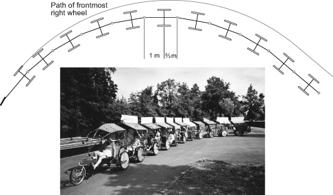
Figure 10.18
Thuner Trampelwurm: photo and path of the complete road train turning left 90°. The shown displacement to the inside is purely geometrical without regard to tire or dynamic forces and is less in practice, when it is possible to form a 360° merry-go-round with only slightly more displacement than one trailer width.
Four complete Trampelwurms were built by unemployed persons in the Swiss city of Thun and extravagantly decorated by local schoolchildren. The ownership and management of what has become a local tourist attraction has changed several times since the start. For many years a group of about ten part-time drivers were employed and trips organized for several thousand persons per year. Now twenty-five years later, nearly half the units have been used up for spare parts, but the others are still going. Although as heavy as an automobile and as long as any legal road vehicle, the Trampelwurm can negotiate the most crowded and narrow pedestrian areas in safety and can also travel on typical roads as long as they are not too steep. Parties enjoy the tricks the drivers perform, like catching up with their train’s own tail, forming a temporary human-powered merry-go-round, or diving into a particular steep narrow tunnel in roller-coaster fashion.
All of the technical difficulties of road trains—tracking or stability, braking, and a high empty weight (i.e., the pilot has to shift nearly a half-ton unaided when pedaling to a pickup point)—could be solved by using motors in some of the wheels, a rather expensive solution for which it would probably be difficult to get official approval. The (unmotorized) Thuner Trampelwurm brakes through a combination of (not very effective) mechanical overrun brakes, (very effective) hydraulic brakes on the front six wheels, an occasional manual “hill brake” in the middle, and an “emergency brake” at the end.
A most interesting problem is faithfulness of tracking. A moment’s reflection will show that for a large number of two-wheeled trailers to track perfectly, they must be constructed symmetrically, that is, the distances from the wheel axis to the hitch points must be the same in the front and in the rear. If all hitch points were ball joints, there would obviously be zero stability in both yaw and pitch, and the whole train could fold completely. The only thing preventing this is the most forward hitch connected to the tractor vehicle, which defines all joint positions for the entire train, but as play accumulates to the rear, they would in practice oscillate, sway, and jackknife. At the other extreme, if the rear hitching distance is zero, that is, each trailer is hitched at the wheel axis of the front trailer, the stability is high, but the tracking in curves is poor, each trailer to the rear moving more and more to the inside. The Thuner Trampelwurm is a compromise: the ratio of forward to rearward hitch distances is 3:2. The tracking is not perfect, but adequate. Figure 10.18 shows the displacement due to the actual geometry. The exact situation at the beginning and end of the curve is unclear and would need a mathematical analysis. In practice there are opposing forces due to tire slip, hydraulic dampers, and centrifugal pseudoforce, so the tracking is better than shown. The speed is, however, limited, as above about 15 km/h swaying oscillations and jackknifing start (in the case of deformed frames or unevenly pedaling riders, even at half this speed). The ratio of hitch distances should therefore probably be increased.
This type of train can also be formed with commercial delta tricycles. The front wheel of a tricycle is connected with a second, pivoting fork to the tricycle in front of it, or more often the wheel is removed and its fork connected directly via a pivoting pin (see Mary 2010 for an account of delta tandem touring). Trains of many more delta tricycles are occasionally formed for fun and records. The longest appears to be a train of ninety-three Hase Kettwiesel trikes demonstrated in 2007. Lateral stability and tracking seems not to have been a problem, but rather the control of pedaling and braking, which was accomplished with “Pedal!” and “Brake!” placards held up at appropriate times. More recent trains of twenty-three to twenty-seven trikes in the United States were more roadworthy but still too long to be really practical. By using sociable trikes the number of passengers per length of train can be increased. Figure 10.19 shows three coupled Gem sociable tricycles made by HPV pioneer Peter Ross. The value of such trains is not technical, but rather in allowing a single guide to pilot a group of people, who can then concentrate on activities such as sightseeing and talking instead of driving.
Cargo Bicycles
Cargo bikes, or freight bicycles as listed in the so-named Wikipedia entry, have been around for a long time, for example, tradesmen’s bicycles with sturdy luggage racks front and rear, various designs from the Netherlands and Denmark, and especially strengthened bicycles for load carrying in Africa. At the time of writing, cargo bikes are starting to become popular, with attractive designs, electrical assist, and trailers with enormous capacity—greater than that of small cars. Many of the many types of vehicles are tricycles or quadracycles (see figure 10.20), but the following subsections mention just two concepts: “long” bicycles and bicycle trailers. Wood (2013) provides an illustrated history of cargo bicycles and tricycles.

Figure 10.19
Train of three recumbent sociable Gem tricycles. (Photo by Jason Patient.)

Figure 10.20
Freight-carrying recumbent quadracycle.
There are many cargo trike manufacturers. One making modular delta-configuration cargo trikes and pedicabs is Cycles Maximus (cyclesmaximus.com) in Bath, England. Tadpole-design cargo trikes are sold by Haley Tricycles (haleytricycles.com) in Philadelphia and Icicle Tricycles (icetrikes.com) in Portland, Oregon. Worksman Cycles (Worksmancycles.com) in Ozone Park, New York, makes traditional bikes, quads, and trikes of both types.
Long Cargo Bicycles
In order to create a generous space for cargo, a bicycle can be lengthened. If the length is added at the rear (as can be done to a standard bicycle, for example; see instructables.com/id/How-to-Build-a-Longtail-Cargo-Bike/), the resulting vehicle is called a long-tail bike.
If a bicycle is instead extended in front, it becomes a Long John, a type first produced about a century ago in Denmark. A low platform is added between the bicycle’s front wheel and steering post, and the handlebars steer the front wheel via a linkage. The wheelbase can be up to 2 m in length, so that slow riding and turns are more difficult than with a standard bicycle, especially without a load, as there is then little weight on the steered wheel. Today many firms produce similar designs under various names for the transport of children or goods. Since electrical assist systems have become popular, Long John–type bicycles so fitted are frequently seen even in nonflat areas. The website Larryvsharry.com shows a popular modular cargo bike, the Bullitt (figure 10.21). A total weight of 180 kg is permissible, including the 24 kg weight of the basic model and that of the rider.
Another website, 8freight.com, shows a different configuration of a long bicycle by HPV pioneer Mike Burrows. On this model, the cargo basket is located behind the rider, so that riding it is more like riding a standard bicycle.
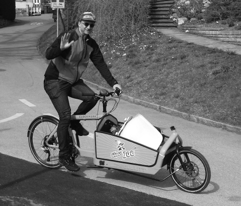
Figure 10.21
Modern Long John–type delivery bicycle.
Trailers
Standard two-wheel, single-axis bicycle trailers can carry large and bulky loads but become dangerous or unusable on steep gradients or when braked sharply. Although the mass, which is usually higher than the wheel axis, then tends to load the bicycle’s rear wheel, giving some extra road friction, it needs only a slight lateral imbalance to create a yawing couple, and if the resulting force is greater than the bicycle can handle, it jackknifes or crashes. An additional problem of long trailers is the severe cutting of corners in tight curves. An Open Source Hardware project called Carla Cargo (werkstatt-lastenrad.de/index.php?title=Bauanleitung_Carla_Cargo_Crowd) addresses both problems using a third wheel that is steered by a long connecting bar containing an integrated mechanical overrun brake for the rear wheels and an electrical brake sensor. A maximum cargo of 150 kg and 1.5 m3 can be transported. For hills, the third wheel can be fitted with a hub motor that is controlled by a pedal sensor on the bicycle and a braking sensor. A commercial version is also available (carlacargo.de/en/) that is not only legal (at least in Europe) but at the time of writing is supported by the German government, which will subsidize 30 percent of the purchase price. It can also be used as a powered hand cart. The control system does not seem as sophisticated as that in the “phantom trailer” concept by Andreas Könekamp (see chapter 9), in which one would ride the leading bicycle as if the trailer weren’t there. However, some “feedback” from the trailer is useful, as caution is in any case required in curves.
Human-Powered Water Vehicles
Almost all water vehicles at rest are supported in or upon the water by buoyancy. This is created by a lighter-than-water hull displacing a volume of water and allowing the water pressure to press the hull upward with the same total force as the weight of the displaced water. For most craft this applies also when moving; they are thus referred to as displacement craft. For reasons given later in this discussion, large human-powered boats and utility craft are of this type, whereas the fastest human-powered racing boats are hydrofoil craft, supported in the water by dynamic lift in the same manner as birds and airplanes in the air.
Water Drag
If other things are equal, the drag of a vehicle is proportional to the density of the fluid in which it operates and to the square of its speed, as described in chapters 4 and 5. Water drag is thus about one thousand times air drag, and speed (for the same power) is ten times less in water than in air. Although other things are not all equal, this ten-to-one rule does apply approximately to comparable vehicles: swimmers to runners, canoes to partially faired bicycles, and rowing shells to fully faired HPVs.
The majority of water-vehicle hulls operate on the interface between water and air, giving rise to sources of drag not experienced by land or air vehicles or fully submerged vehicles. The water pushed away by the moving hull produces surface waves, and struts piercing the surface create spray. Both remove energy and create additional resistance to movement. The wave drag can be relatively small for very large hulls (ships), very slim hulls (rowing shells, multihulls), or very flat hulls (stand-up paddling [SUP] boards). For others, including canoes and pedaled boats wide enough for reasonable stability, it tends to become especially large just at the bicycle-like speeds at which one would like to travel, in effect creating a kind of limiting speed called the hull speed, about 1.3 m/s times the square root of the waterline length in meters (e.g., under 2.3 m/s for a 3 m long boat). High-powered motorboats or sailboats can exceed the hull speed by dynamically lifting the hull when it planes on the water’s surface. This reduces both wave making and the hull’s wetted surface. Complete planing does not appear achievable with human power (just as running on the water’s surface is also not achievable by ordinary humans, even though some lizards are able to do it!). However, other forms of dynamic lift are possible with human power, notably using hydrofoils or underwater wings. Once moving, hydrofoils can lift a boat and rider out of the water. Julius Schuck demonstrated his unique Wasserläufer in 1953, traveling sideways and relatively slowly on top of two large hydrofoils. Nobody else appears to have experimented with large hydrofoils for human-powered boats because there is no advantage: the water drag generated by such hydrofoils is greater than for a fine displacement hull. However, if the hydrofoils are made small enough to generate just the required lift at maximum human power, they allow the highest purely human-powered speeds currently achievable on water.
Speed Vehicles
Sailing hydrofoil pioneer James Grogono fitted his rowing shell with hydrofoils and in 1975 was able to fly briefly using the oars, but the first human-powered hydrofoil to demonstrate sustainable flight was Flying Fish (figure 10.22) in 1983 (see Abbott and Brooks 2013 for a description, including spectacular videos, and Brooks 1987 for technical background). The above-water configuration is much like that of a bicycle, with the handlebars connected to a front assembly employing a rudder and a small horizontal hydrofoil. A surface follower maintains the proper depth a little below the water surface, which indirectly also sets the depth of the main weight-bearing horizontal hydrofoil located on a strut below the rider. The pedals are connected by a thin twisted chain to a propeller mounted on this strut.
For the first experiments in which it was involved, Flying Fish was launched from a kind of catapult, as it could not start to fly from the water. With only the frame and rider visible, this gave it a spectacular “water bicycle” appearance, which has since been duplicated by a slower craft called Waterbike (see the website human-powered-hydrofoils.com for this as well as a dozen other craft). In order to allow repeated flights away from the shore, Flying Fish was fitted with two lightweight inflatable pontoons developed by the coauthor using methods of his employer, Keith Stewart. With three or four strong pedal strokes, the hydrofoils lift the pontoons out of the water, and flying begins. Abbott likens the riding and balancing of Flying Fish to riding a bicycle on a very smooth road. In 1987 he set a record for 100 m at 12.94 knots (kn).

Figure 10.22
Flying Fish propeller-driven hydrofoil by Allan Abbott (shown) and Alec Brooks.
Flying Fish was immediately faster than rowing shells. With a run of 11.15 kn (5.74 m/s) in 1987, it holds the single-rider speed record for 2,000 m (standing start), somewhat faster than the best single-scull rowing shell even today. Shells for eight rowers are nominally faster over this distance (the 2017 world record is 12.21 kn, 6.28 m/s), but the wind conditions for rowing records are not closely controlled or in many cases even published.
In 1989 a chemical firm offered a prize of $25,000 for the first single-person human-powered water vehicle to reach a speed of 20 kn (10.3 m/s) for 100 m (flying start) before the end of 1992, or in the event no vehicle of that type achieved such a speed, for the vehicle that had reached the highest tested speed (under strict rules) by that date. The competition for this prize stimulated much activity. The Flying Fish team intended to try, and several others, including the MIT group that had successfully mounted the Daedalus human-powered airplane effort (see discussion later in the chapter). They decided to enter with a craft using an air propeller, as employed in their aircraft. This gave the team an advantage, unforeseen by those who set the rules used for this competition, which allowed a maximum wind speed of 6 km/h (1.67 m/s). (The relevant IHPVA and WHPVA water rules have since changed and now allow no vehicle speed advantage greater than 1 percent compared to a no-wind situation.)
A water vehicle using air to generate thrust has a bonus when traveling with a tailwind. For example, if it is traveling at 10 m/s with a propulsive power of 800 W (= 1 kW input times 80 percent efficiency), the thrust is 80 N, and a 1.5 m/s tailwind contributes 80 × 1.5 = 120 W of this (at 100 percent efficiency), 12 percent of the total input power (in practice a bit less). The MIT team’s use of an air propeller (much larger than a water propeller) also meant having to cope with its high pitching moment. Wall, Drela, and Finberg (1995) superbly document the craft’s development. The team also designed a unique laddered hydrofoil with a large foil for initially lifting the craft (initially supported by catamaran hulls) out of the water and a smaller foil below this for full speed, with the large foil then pivoted out of the water. Their craft Decavitator (figure 10.23) didn’t quite reach 20 kn, but it won the prize with a speed of 18.5 kn (9.5 m/s). In 2000 the tandem hydrofoil boat Super Phoenix, with a water propeller, achieved 18.67 kn (9.6 m/s).
Why are the top speeds of even hydrofoil-equipped boats so low compared to those of land vehicles? It isn’t the propulsion, as the best propellers can exceed 90 percent peak efficiency (see later discussion); it has to do with the energy cost of supporting any weight, which can be expressed as a lift-to-drag or weight-to-resistance ratio. For a displacement hull, this ratio increases to very high values at low speeds and large sizes (see later discussion). Such a hull is useful for moving cargo, but not for small racing boats, for which hydrofoils are superior. The best hydrofoils could be expected to have a lift-to-drag ratio of about 50:1, like sailplanes, but this doesn’t include the considerable drag of one or more surface-piercing struts needed to connect the underwater parts with the rider and above-water parts, nor does it include the slight wave-making drag of the foils, which cause a slight depression in the water surface unless very deeply submerged. Therefore the flights of hydrofoil boats are less efficient than those of airplanes and are mostly slower and shorter.

Figure 10.23
Decavitator world-record-setting pedaled hydrofoil. (Courtesy of Mark Drela.)
In contrast the lift-to-drag ratio of wheels (including tires and bearings) on hard surfaces, or runners on ice, can be several hundred to one. With this in mind, inventors have experimented with boats rolling over the water on buoyant tracks. Long, well-shaped tracks synchronized to the forward movement could nearly eliminate wave-making and water-friction resistance at the same time, replaced by the drag of wheels and their bearings. But here theory and practice are very far apart. The tracks splash or at least throw about clinging water, as shown in figure 10.24. They must be large, and then they generate considerable air drag, especially as the top parts of synchronized tracks are moving forward at twice the vehicle speed.
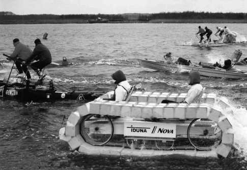
Figure 10.24
Thusnelda human-powered boat with tracks, during the 1991 European Human-Powered Boats Championships in Gdansk, Poland. (Photo by Christian Meier.)
One way to go faster over water would be with a flying boat. Considering that human-powered airplanes can exceed 20 kn (see later discussion), one flying very low over the water surface should be faster, as the lift-to-drag ratio is greater the closer the wing is to the surface below, in what is known as ground effect. Of course such a vehicle might not be considered to be a water vehicle, unless perhaps if it were able to take off from the water, which is more difficult than taking off from a runway. A more practical and possibly even faster proposition could be a true human-powered wing-in-ground-effect flying boat. Such a craft has a lower-aspect-ratio wing than an airplane, but the wing’s tips or endplates almost touch the surface, minimizing induced drag. A diagram in Hoerner and Borst (1975) suggests a 100 percent increase in the lift-to-drag ratio (relative to free flying) for ram wings with aspect ratios from 1:1 to 4:1, with end plates almost touching the surface, and maximum lift-to-drag ratios from 25:1 to 60:1. Flying closely over the water, however, creates additional wave drag, from the shallow impression in the water surface under the craft. Many large wing-in-ground-effect craft have been built, but we don’t know of any human-powered ones. However, Steve Ball built a human-powered hovercraft with sidewalls, fan, and air propeller, the fan absorbing about one-third of the total power (Hostetter 1990–1991). His craft Dragonfly III is reported to have reached 7 m/s (13.6 kn) and was officially timed at 5.9 m/s (11.47 kn) over 100 m.
Submerged Buoyancy: A Warning
Some fast industrial and military craft are constructed as small-waterplane-area single-hulls. These are trimarans or even monohulls with most buoyancy concentrated in a submerged torpedo-like hull with minimal wave drag (see Bluebird Marine Systems 2014 for an overview). This hull is connected to the craft’s above-water parts by a thin strut. Obviously this creates an unstable inverted pendulum, like a bicycle or unicycle, and must be balanced both statically with adjustable buoyancy chambers and dynamically by actively controlled fins. The coauthor built a human-powered one and naively hoped to balance it like Flying Fish (described earlier in the chapter) and to achieve very low drag because of both minimal wave making and minimal surface area. However, unlike hydrofoil craft, which permit gentle transition from static buoyancy to dynamic lifting as they speed up, this craft had really vicious capsizing and pitching moments at rest, acting much faster than the rider could react (Schmidt 1985), and it only ever worked once—and then very slowly—with four additional draggy stabilizing outriggers. Although such a craft might work better with a fast-acting automatic control system, only partial buoyancy, or both, the reader is forewarned, and we urge anyone tempted to try this to go straight to a triangular arrangement of three such hulls, for the same reasons that a tricycle is much easier to ride than a unicycle.
Recreational and Utility Watercraft
Human-powered marine vehicles have been in use since prehistoric times, mainly paddled, canoe-like monohulls and multihulls, later also rowed craft, even quite large ones (see figure 1.1). In quite a few places around the world, marine vehicles are the main means for transporting goods, often worked by paddles, oars, or a single “sculling” oar often called a yuloh (see Groves 2008 and Hawley 2014). In the city of Venice, the famous gondolas are today only for special events and tourists, but the seven traghetti are public ferries in constant use, for up to a dozen standing passengers, powered by two standing rowers (see Venipedia 2012). The discussion here could include a great many other interesting human-powered transport boats, but reasons of space restrict it to a few observations and very few special examples.
Hull Efficiency
In the absence of wind, waves, or currents, a person can shift great loads on a barge by pulling from land with a rope, pushing with a pole, or with a large hydrodynamic propulsor. This is not only because there is no slope resistance, but also because the frictional drag of a displacement hull decreases with about the third power of the speed decrease, that is, it gets arbitrarily small as the craft goes slower. This can be expressed as a lift-to-drag ratio, which is the same as weight times speed divided by power, the inverse of what is called the specific resistance. If we assume a high propulsive efficiency, a single person can shift any load by going slowly enough, and the lift-to-drag ratio can become very high. As resistance increases only by a power of two-thirds of weight, making a water vehicle bigger and going slower increases the efficiency of transportation to any value. Even if only the load is counted, not the weight of the person driving the craft, and assuming 20 percent muscular efficiency and subtracting the basal metabolic rate (see chapter 2), this still holds true, although the increase is less. However, at some point increasing the size further will become impractical. A great deal of effort will be needed to accelerate the load, and any wind will begin to dominate, so that transporting more than 50 tonnes (1 t = 1,000 kg) per person is rarely feasible. With this 50 t displacement and a propulsive power of 500 W, a hypothetical optimal hull would move at about 1.5 m/s and achieve a lift-to-drag ratio well over 1,000:1. Or if the human “engine” is treated as a fuel cell with 20 percent efficiency and a basic metabolic rate of 450 W (food) input is subtracted, an energy-cost lift-to-drag ratio greater than 200:1 is still attained (see figure 10.25).
From the foregoing it is clear that hydrofoils (or planing hulls) are not suitable for human-powered utility craft because the high lift-to-drag ratios available from displacement hulls are not achievable. Even recreational human-powered hydrofoils (other than hybrids) are only marginally suitable, as fast flight is sustainable only for a limited time. For practical boats, a single hull is usually optimal, provided it is either operated at a speed at which wave-making drag is not excessive, or slim enough (rowing shell) or flat enough (SUP board) for the same aim. However, a rowing shell, very narrow and round, is really a trimaran, as it relies on oars for maintaining stability, just as racing kayaks and canoes depend on paddles for this. Boardlike hulls, on the other hand, are very stable but have a large proportion of wetted surface area relative to their volume. Narrow-hulled boats with pedal drives get stability by adding a single outrigger (proa) or two outriggers (trimaran). The latter can be particularly efficient with the floats just touching the surface but are impractical for disembarking at a jetty. More practical and frequent is the catamaran configuration with two same-sized slim hulls. These are stable, fast, and practical but have ![]() more wetted surface area than a geometrically similar single hull with the same volume.
more wetted surface area than a geometrically similar single hull with the same volume.

Figure 10.25
Lift-to-drag ratios of hypothetical hulls with negligible wave drag being propelled by human power (pulled from land with a rope or winched) at 500 W (2,500 W food input).
Optimal Propulsion
A propulsor can approach 100 percent efficiency by accelerating a huge body of fluid by an imperceptible amount. This is expressed by the Froude efficiency and the actuator-disk theory (the projected area swept by a propeller blade more or less describes the actuator disk area). In essence, if the slip is defined as the ratio of the fluid velocity increase through the actuator disk to the vehicle velocity, the Froude efficiency can be expressed as 1/(slip + 1). Therefore, paddle wheels or other very large drag-producing devices theoretically tend toward 100 percent efficiency if they are large enough. However, as in the case of the tracked boat (discussed earlier in the chapter), clinging water, splashing, air drag, and fragility limit the efficiency that can be obtained, and practical, robust paddle wheels are too small for really high efficiency. Even lower efficiencies are realized by the jet drives sometimes proposed for human-powered boats. The relatively small cross sections of water jets (i.e. small actuator disks) mean that the water ejected backward carries with it considerable kinetic energy, which is then lost to the system.
The highest-efficiency embodiment of an actuator disk (here an actuator rectangle) would be a high-aspect-ratio foil or a pair of such foils moving at an angle of approximately 45° to the direction of travel at such a speed that the angle of attack to the apparent flow is at the optimal lift-to-drag ratio, usually a few degrees. Fast fish like sharks and mammals like whales and dolphins move their tail fins this way to some degree. An efficient mechanical embodiment it is, however, difficult to construct, even though the efficiency of a pair of opposing foils is limited only by their lift-to-drag ratio (including induced drag). The coauthor developed both horizontal and vertical foils with theoretical high efficiency, but they were pretty useless in practice. More successful have been Harry Bryan, Cal Gongwer, and others (see Bryan 1994 and Langenfeld 2009). Several “hopping” hydrofoils that combine propulsion and support in the same hydrofoil have also been built and even sold. These haven’t been a commercial success so far, probably because water starts are not possible: once back in the water after a short ride, the rider has to swim back with the device. More successful are modern embodiments based on SUP boards, which allow buoyant slow-speed operation and momentary (very brief) flights through simultaneous hopping and paddling. They are, however, not sold for such operation, but rather for foil-borne surfing even in very low-amplitude waves.
If propulsive foils can pivot like birds’ wings, it makes their functioning easier. Anybody who has watched videos of penguins swimming underwater has no doubts about this obviously effective and apparently efficient mode of propulsion. A most successful technical embodiment is Hobie’s Mirage drive, which since 1997 has been used on many Hobie craft and is also available for use on other boats. In a boat equipped with the Mirage drive, a pair of opposed flexible foils both swing through nearly 180° under the boat, sweeping a larger area than most propellers (resulting in a large actuator half-disk). Although the device will not win races against optimized propellers and cannot propel a boat backward, it is otherwise highly practical, being able to operate in both deep and very shallow water, and is easily cleared of weeds.
For completeness, we mention low-aspect-ratio flexible fins as used very successfully by most fish and by human swimmers, but we know of no other human-powered technical usage.
Finally, there are propellers, which are not used in nature other than in a sense by bacteria at extremely low Reynolds numbers but are extremely successful in human-powered boats. Their propellers are more efficient than motorboat or ship propellers, which are highly restricted by draft and changing water lines. Human-powered boat propellers can be large enough to achieve a high Froude efficiency (see foregoing discussion). The more resistance a boat has, and therefore the slower it travels with a given amount of power, the larger the propeller must be. Propeller blades are limited by their local lift-to-drag ratios and losses due to tip vortices, resulting in overall best efficiencies from about 85 percent (practical boats) to 90 percent (extreme boats) to ~95 percent (structural limit). Propellers for human-powered racing boats are designed rather like aircraft propellers, with slightly wider blades for practical boats. Here an overall good efficiency over a wide speed range and high thrust in adverse winds is more important than a peak efficiency that exceeds 90 percent at a single operating point. The coauthor’s “standard” propeller has a diameter of 0.5–0.6 m, about the same amount of pitch, and two blades about 90 mm at their widest. A “racing” version is similar, but a bit smaller and with blades half as wide. A simulation program shows that such propellers operate most efficiently at a Froude efficiency between 95 and 98 percent (see Larrabee 1984, 2003, and Schmidt 1988, 1999).
Most nontraditional human-powered boats employ propellers, and at least one manufacturer (Sea-Cycle) sells complete pedal drives, which can also be used on other boats. Sea-Cycle’s drive and similar drives (like that of Flying Fish described earlier) employ a chain, with the chainwheel and driven cog twisted 90°. Some recreational boats are offered with air propellers, even though at the speeds achievable, the propellers are too small to achieve a high Froude efficiency, and they are more expensive than water propellers. Advantages include zero draft, weed-free operation, and often variable-pitch blades for always optimal adjustment.
Hybrid Boats
The combination of wind and human power is age old, that of human and electric or even solar power relatively recent. A new development is an aquatic pedelec with a design similar to Flying Fish described earlier in the chapter but able to do water starts without pontoon floats. It is also slower than Flying Fish, with cruising speeds of 6–9 kn. The coauthor managed a very short hybrid flight with his own catamaran and hydrofoils supplied by David Owers, but normally used the solar- and human-powered boat in displacement mode. In the years around the turn of the millennium, there were numerous races for such boats. The advantages of hybrid operation include slightly better performance, better reliability, and adjustability to the operator’s body and mental state: if cold or bored, pedal faster; if tired or hot, pedal slower.
Escargot
The late Philip Thiel (1991) had produced plans for a range of utility boats, including a tiny pedal-powered houseboat for cruising canals, propelled by one or two people using Sea-Cycle drives, with sleeping berths for up to four, toilet, and kitchen. This craft, Escargot (figure 10.26), had a rather unique design and was quite popular, with quite a few having been built. Unfortunately, the original plans have been replaced by a version with an outboard engine. The Sea-Cycle drives were designed for lighter, faster craft and not ideal for the Escargot’s displacement, as the coauthor found out himself. The original Escargots, still available for hire in Germany, have modified propellers and a cruising speed of 3.5 kn (see whpva.org/HParchive/hp55p22-23.pdf). Instead of optimizing the human-powered drive, perhaps also with a solar-assisted hybrid, the Escargot plans now call for at least a 1.5 kW (2 HP) outboard motor for a speed of 4–4.5 kn. This great decrease in efficiency is mainly due to a smaller propeller area.

Figure 10.26
Escargot pedal-powered “Pénichette” by Philip Thiel.
Human-Powered Submarines
The IHPVA organized the first international human-powered submarine race in 1989, and since then a dozen others have been conducted by other organizations. An entire issue of Human Power edited by P. K. Poole (1993) offers guidance on design parameters for human-powered submarines and describes five submarines by teams competing in the 1993 race. Since then the greatest success in submarine competitions has been achieved by the Omer series of submarines, designed and built by students at the École de Technologie Supérieure in Montreal (see also the discussion of this school’s helicopter project later in the chapter). The hull of the one-person Omer 3 (with a variable-pitch propeller) has at its widest point a diameter of 610 mm and at its longest point a length of 2.75 m. The maximum speed reached (in 1999) was nearly 7 kn, which was very high for this type of vehicle, almost all others having top speeds of less than 5 kn. Omer 8 in 2013 achieved 7¼ kn. The Omer 5 two-person submarine even reached 8 kn in 2007, the current world record (the records for both one- and two-person submarines are with a flying start and timed over 10 m). The very productive Omer project has a Wikipedia page and its own website, with descriptions of, but no data on, its eleven submarines (clubomerets.com).
The current (2018) record speed for a one-person submarine, at just over 7.4 kn, was achieved in 2016 by students of the Delft University of Technology forming the WASUB team (wasub.nl). The impressive design report for their WASUB V submarine is available from a page on the International Submarine Race website (internationalsubmarineraces.org/13th-isr/). The WASUB V’s hull is roughly 2.5 m long, 0.5 m wide, and 0.6 m high, with 3.7 m2 surface area, and was modeled on a NACA 0020–44 laminar profile. It has counterrotating two-bladed propellers 0.36 and 0.43 m in diameter, with a design speed of 350 rpm at 7.5 kn and the pilot furnishing 800 W at 100 rpm.
The European competition website (subrace.eu) has further general information and links to extensive video material on human-powered submarines.
Modern human-powered submarines are flooded, that is, piloted by divers with breathing equipment. The energy needed to compress the air in a diver’s air tank is greater than that used for propulsion (e.g., compressing 1 m3 of ambient air into a 200 bar tank requires well over 0.5 MJ). However, dry submarines are much more complicated and dangerous (the Hunley, noted later in this paragraph, sank and killed its crew three times). Historically, human-powered naval submarines were built as pressure vessels containing air. The very first such submersible, the famous Turtle of 1775, was powered by one man. The US Navy’s first submarine, Alligator, was launched in 1862 (at the time of the Civil War). The 14 m long, 1.4 m wide iron vessel initially had 16 or 18 pairs of underwater paddles for a crew of 17, achieving a speed of 2 kn with these, and a year later 4 kn with a 1.6 m propeller (see navsource.org/archives/08/08444.htm). The well-documented 7 ton Confederate submarine L. H. Hunley attained a speed of 4 kn with a propeller cranked by eight men.
Human-Powered Aircraft
The Kremer Prizes
Human beings have tried to imitate birds for at least two millennia. Leonardo da Vinci sketched a helicopter, and many nineteenth-century experimentalists dedicated themselves, and sometimes their lives, to demonstrating human-powered flight, without success. Some short “hops” were achieved in the 1920–1960 period. In 1959 Henry Kremer, a British industrialist, was persuaded in a moment of weakness to offer a prize of £5,000 (then equivalent to about $20,000) for the first human-powered aircraft to fly a figure-eight course at least 10 ft from the ground around two pylons 0.5 mi apart. Nearly two decades later, in 1977, Paul MacCready’s Gossamer Condor won the prize. Kremer was delighted and agreed to offer a series of prizes, starting with one for a human-powered crossing of the English Channel (La Manche). This prize (£100,000, then worth $180,000) was won by another MacCready plane, the Gossamer Albatross, in June 1979. (The prize money awarded in this case seems a substantial sum. However, if a government commissioned the development of a human-powered plane to cross the Channel, it would cost many times this. Kremer’s generous prizes stimulated an enormous amount of interest and activity, out of proportion to the amounts involved.)
The Gossamer aircraft have been given a great deal of well-deserved publicity. The discussion here illustrates human-powered flight with two other remarkable aircraft series: the Musculair and the Daedalus. It also mentions some helicopter and dirigible projects. A full description of human-powered aircraft is given by Roper (1995).
The Musculair Aircraft
Musculair I was built by the late Gunter Rochelt and his son Holger, supposedly a compromise design to win two different Kremer prizes. The younger Rochelt, characterized by Roper (1995) as “not particularly athletic,” was designated as the pilot. However, he won the non-US figure-eight prize in June 1984, shortly after the Musculair I’s first flight. He also took his younger sister Katrina up for a short trip: the first passenger flight of a human-powered aircraft. In August of that year he won a second Kremer prize, for speed around a circuit. The rules governing the Kremer prize allowed energy storage to be used; the energy had to be generated by the pilot during the 10 minutes preceding the flight and stored on board the aircraft. The Rochelts decided that they could do better without energy storage and proved themselves right. The wings of their aircraft also had a quarter of the wing area of the Gossamer Condor and no wing bracing. The flight was a remarkable achievement, technically, and also physically for someone “not particularly athletic”!
The Musculair I was unfortunately destroyed in 1985 in a traffic accident while being towed in its trailer. The Rochelts built a new version, Musculair II (figure 10.27), aimed at winning another speed prize. (Successive Kremer prizes could be awarded for a 5 percent improvement in speed over the previous record.) Holger Rochelt won a third Kremer prize for what had earlier been regarded as an unbelievable speed of about 12.5 m/s (23.9 kn, 44.3 km/h, 27.5 mph) on October 2, 1985, around a triangular 1.5 km course. Roper (1995) reports that the Royal Aeronautical Society, the prize administrators, closed the Kremer speed prizes shortly afterward because it was considered impossible to exceed Rochelt’s speed by another 5 percent.
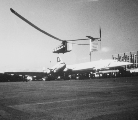
Figure 10.27
Musculair II at the Basel Air Show, 1985; a DC-3 (left) and a Concorde (right) can be seen in the background. (Courtesy of Ernst Schoberl.)
Daedalus
Students at MIT, along with faculty members and other advisors, designed and built a biplane, Chrysalis, as preparation for an attempt to win the cross-Channel Kremer prize. (The senior author was one of the many permitted to power and pilot it.) Later they built the monoplanes Monarch A and Monarch B and won a Kremer speed prize. They could not hope to surpass the Rochelts’ speed, however, and in 1985 they began considering a remarkable flight that had no monetary prize: a re-creation of the mythic flight of Daedalus, from Crete to Greece. The destination chosen was actually the island of Santorini, 119 km from the launching site on Crete. The aircraft they created for this endeavor, the Daedalus (figure 10.28), and its Greek pilot Kanellos Kanellopoulos were successful on the first attempt, even though the aircraft broke up at the very end as it was hit by a rather violent crosswind just as it was coming in to the beach on Santorini.
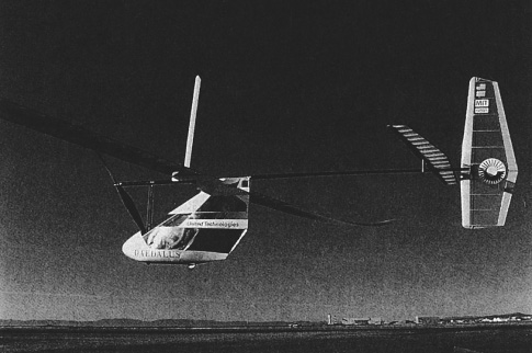
Figure 10.28
Daedalus world-record-distance human-powered airplane. (Courtesy of Mark Drela.)
The crossing of the Daedalus was possible only as the result of a great deal of preparation that is described by Nadel (1991) and in chapter 2. For example, the team devised and tested an energy drink containing 10 percent glucose and 0.4 g sodium per liter, to be consumed at the rate of 1 L/h during the 4 h duration.
Most human-powered aircraft before the Daedalus had used a lightweight steel-cable chain substitute (see chapter 9) to transfer the pilot’s power from the pedaled shaft to the overhead propeller shaft at right angles. In the Daedalus, power was instead transmitted by means of two sets of bevel gears and a torque tube. The design was a remarkable accomplishment, simultaneously saving weight, achieving greater reliability, and producing a higher transmission efficiency with a drive that, when applied to bicycles, has up to now generally been heavier and less efficient than the chain drive it has replaced.
Recent Human-Powered Airplanes
Today about a hundred human-powered airplanes have been built. A more recent focus for new craft and prizes is practical usage in normal weather and over long distances. An example is Pennsylvania State University’s PSU Zephyrus, based on the Musculair II, which is used for classes and in competing for a new Kremer Sports Prize (see Royal Aeronautical Society 2018 for details of this and also a new Marathon Prize). One of the newest ongoing projects is Alec Proudfoot’s brainchild Dead Simple HPA (see dashpa.blogspot.com). The Japan International Birdman Rally has an event for long-distance human-powered airplanes, and in 2019 the Team Birdman House Iga won the first prize with a flight of 60 km in 2 h 36 min. The next-best team achieved 38 km, and the fifteen Japanese teams totaled 135 km (see https://japanesehpa.wordpress.com).
Human-Powered Helicopters
In 1980 the American Helicopter Society offered a prize, named after the helicopter pioneer Igor I. Sikorsky, for the first human-powered helicopter to hover for 1 minute and to reach a minimum height of 3 m for at least a moment. The winning helicopter also had to remain over a 10 m square, support at least one (nonrotating) member of the crew, and obtain lift solely through rotating elements. Figure 10.29 shows some of the concepts developed to attempt this. The prize was won three decades later, in 2013, by the AeroVelo team with their human-powered helicopter Atlas (see vtol.org/hph/ and figure 10.30). This is the largest helicopter ever constructed, with an overall width of 58 m (190 ft) and four 20.4 m (67 ft) diameter rotors, but weighing only 52 kg (115 lb)!
Human-Powered Blimp: The White Dwarf
Piloted by its designer, Bill Watson, the nearly 15 m long White Dwarf human-powered airship (figure 10.31), conceived and owned by the popular comedian Gallagher, is filled with approximately 170 m3 (6,000 cu ft) of helium. Its 1.6 m diameter propeller, mounted on a pylon behind the pilot, can have its thrust angle altered through nearly 100° to allow altitude control via a hand lever. Two triangular tanks, under and behind the pilot, carry water ballast up to a total of 114 kg (Allen 1985). Using the methods and data presented in chapters 4 and 5, a blimp of this shape and size should move at about 12 kn with 100 W propulsive power, that is, before the external structure and rider and the losses from the propeller and drive train are considered.
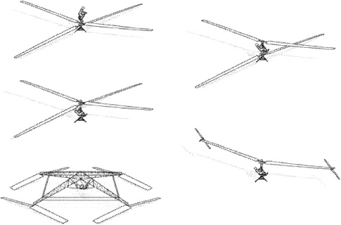
Figure 10.29
Conceptual designs for a number of human-powered helicopters from Doug Furton (2000), the supervisor of Project Helios at the École de Technologie Supérieure, Montreal. Those in the left-hand column were developed under the direction of Akira Naito (1991) at Nihon University in Japan. The lowermost of these, the Yuri I, and the Da Vinci III, at the lower right, were the first human-powered helicopters to fly. Helios, upper right, is most similar to the early two-rotor Naito designs. The AeroVelo Atlas is also of the Yuri I type. (Courtesy of Doug Furton.)
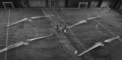
Figure 10.30
AeroVelo Atlas a year before achieving its record flight. The four rotors counterrotate pairwise. They each completed nine revolutions during a 1 min hover during the record flight. The seat with pedals and the single rider are (not discernable) in the middle, the lattice structure practically invisible. Eight yellow markers show the 10 m square. (Courtesy of AHS International.)
The Kremer Prize cross-Channel pilot Bryan Allen (1985) says that human-powered blimps seem to be the only type of human-powered aircraft that can provide recreation and possibly utility with reasonable availability. Successful flights by winged heavier-than-air human-powered airplanes are typically preceded by long periods of waiting for light winds, and they must be stored disassembled or indoors. The White Dwarf, although slower with its 7–9 kn cruising and 12 kn top speed, is smaller and stronger than these airplanes, with their large and fragile wings. Two persons can ground-handle the White Dwarf in winds up to 14 kn, and it can be tethered in stronger winds. Allen describes a trip he took over the California countryside on a lazy summer day, requiring little power input, floating over communities in relative silence, and able to greet and talk with people below him (often to their considerable surprise). He thinks human-powered blimps are a way for almost any person to fly and have fun, but the loss of valuable and expensive helium (roughly 0.25 percent per day for the White Dwarf) sensibly requires group use and organization. (Cheaper and renewable hydrogen could be used if the required precautions are taken.)
A less optimistic picture appears from following the experiences of Stéphane Rousson (2014) with his beautiful pedaled blimp Zeppy. He used his 190 m3 aircraft successfully in many events indoors or in very calm conditions but never achieved his aim of crossing the English Channel. An award-winning short film by Loic Tanant (2009) shows Rousson’s two attempts in 2008. In spite of relatively good low-wind conditions, Rousson is seen plagued by control and safety problems, fatigue, and wind from unfavorable directions. The blimp’s two propellers don’t just provide propulsion but are needed to constantly adjust altitude and attitude, which they do with a relatively low efficiency when fighting gusts. Rousson had to give up both times he tried. (The coauthor is full of sympathy, also having had to give up two Channel crossings: once with a semiamphibious pedaled tricycle and once with a purely solar powered catamaran.) A much longer television film by James Woodroffe in 2016 (https://www.youtube.com/watch?v=8Fve2Stn1II) shows the television adventurer Guy Martin thoroughly training for a further cross-Channel attempt with Rousson’s Zeppy. The exceedingly fine balance of bouyancy required is shown (already disturbed by a brief moment of sunshine heating the gas or clinging moisture), as well as the skill needed to maneuver even indoors. On the day of the intended crossing, conditions are marginal, but Martin is fit. However, he is blown off course and after a few miles Rousson stops the attempt. Martin is able to return to the start, with a more favorable wind direction reaching 13.7 kn. (Rousson can achieve higher speeds when sailing his Zeppy [now called Aerosail] by means of an attached “water kite” known as Seaglider or Hapa, a system also applicable to larger blimps.)
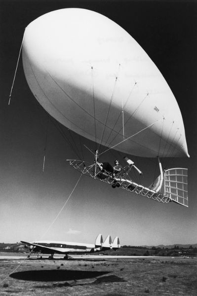
Figure 10.31
Human-powered blimp White Dwarf. (Photo by Bryan Allen.)
Exercise Bicycles and Virtual Cycling
Chapter 2 briefly described stationary bicycles used as ergometers. Many people have similar devices at home and use them for exercise or rehabilitation instead of cycling outdoors. For some people or situations this is important—for example, if going outdoors is especially unpleasant or overwhelming or presents special risks. Less necessary and often a bit absurd is the trend of fit and strong people driving cars to central fitness centers and then cycling on exercise bicycles there. This often happens partly because exercise bicycles and related machines have become sophisticated, large, and expensive devices that are best shared and not owned. They not only act as ergometers but can be programmed to monitor and achieve fitness goals. Motivation is improved through “gamification” and virtual environments presented using screens, virtual-reality headsets, and even physical feedback. Connections to the internet permit virtual racing against real people doing the same anywhere in the world, represented by onscreen avatars—this is also available to those who train at home, so long as they have a computer connection. Athletes who use such systems in addition to normal training report the danger of addiction and overexercise. Others enjoy “cycling” in interesting virtual environments, even in groups. Some dystopian science fiction films have described future human beings as nearly immovable creatures firmly connected to machines providing every satisfaction. Maybe such virtual-cycling programs will at least keep them human in the physiological sense.
References
Abbott, Allan, and Alec Brooks. 2013. Flying Fish: The First Human-Powered Hydrofoil to Maintain Flight (website). http://flyingfishhydrofoil.com.
Allen, Bryan L. 1985. “Blimps and Human-Powered Flight.” Human Power 3, no. 3 (Spring): 1. http://www.ihpva.org/HParchive/PDF/12-v3n3-1985.pdf.
Bluebird Marine Systems. 2014. “SWASH—Submerged Single Hull with Active Stabilization.” http://bluebird-electric.net/SWASH_Submerged_Single_Hull_Active_Surface_Stabilization.htm.
Brooks, Alec. 1987. “20-Knot Hydrofoil.” Human Power 6, no. 1 (Spring): 1, 8–14. http://www.ihpva.org/HParchive/PDF/19-v6n1-1987.pdf.
Bryan, Harry. 1994. “Fin Power—Success Comes from Copying Nature.” Human Power 11, no. 1 (Winter-Spring): 6–9. http://www.ihpva.org/HParchive/PDF/36-v11n1-1994.pdf.
CPSC (Consumer Product Safety Commission). 2019. “Toys & Children Products.” CPSC, Washington, DC. https://www.cpsc.gov/Research--Statistics/Toys-and-Childrens-Products.
Dovydėnas, Vytas. 1990. “Velomobile.” Verlag Technik GmbH, Berlin.
Downs, Daniel. 2011. “Ackermann Steering Geometry Applied to a Skateboard Truck.” Digital Commons, California Polytechnic State University, San Luis Obispo, CA. https://digitalcommons.calpoly.edu/imesp/94/.
Federal Ministry of Justice. 2019. “Elektrokleinstfahrzeuge-Verordnung—eKFV” [Miniature Electric Vehicles Regulation]. https://www.gesetze-im-internet.de/ekfv/.
Fuchs, Joachim. 1996. “Aeolos-Verkleidung” [Aeolos-Fairing]. Pro Velo 44: v.
Furton, Doug. 2000. “Helios: A Helicopter with Legs.” Rotor & Wing (April).
Glanzmann, Lilia. 2011. “Design-Piraten” Hochparterre , nos. 1–2.
Gloger, Stefan. 1996. “Entwicklung muskelkraft-getriebener Leichtfahrzeuge” [Development of Muscle-Powered Light Vehicles]. Fortschritt-Berichte VDI [VDI Progress Reports], no. 263. VDI-Verlag Düsseldorf.
Groves, Robert. 2008. “Some Thoughts on the Yuloh.” Junk Rig Association Newsletter, no. 54. https://junkrigassociation.org/Resources/Documents/Slieve%27s%20Files/Yuloh%20efficiency.pdf.
Hawley, Jim. 2014. “Physics of a Stern-Fixed Single-Blade Sculling Oar like a Yuloh.” Article 36. JimHawley.ca. http://jimhawley.ca/downloads/Physics_of_a_stern_sculling_oar_like_a_yuloh.pdf.
Henshaw, David and Richard Peace. 2010. Electric Bicycles. Dorset, UK: Excellent Books. ExcellentBooks.Co.UK.
Herslow, Joel. 2011. “Hybrid Mower.” Joel Herslow Industrial Design (website). https://cargocollective.com/joelherslow/Hybrid-Mower.
Hoerner, S. F., and H. V. Borst. 1975. “Fluid-Dynamic Lift.” Hoerner Fluid Dynamics, Brick Town, NJ.
Hostetter, Daniel. 1990–1991. “Dragonfly III.” Human Power 8, no. 4 (Winter): 5–6. http://www.ihpva.org/HParchive/PDF/28-v8n4-1990.pdf.
Inria. 2018. “FREEwheels.” Inria, Rocquencourt, France. https://freewheels.inria.fr/.
Langenfeld, Christopher. 2009. “PowerSwim” (compilation). Rex Research (website). http://www.rexresearch.com/powerswim/powerswim.html.
Larrabee, E. Eugene. 1984. “Propellers for human-powered vehicles.” Human Power 3, no. 2 (Winter): 9–11. http://www.ihpva.org/HParchive/PDF/11-v3n2-1984.pdf.
Larrabee, E. Eugene. 2003. “Minimum Induced Loss Wings and Propellers for Human-Powered Vehicles (May 1985).” Human Power, no. 54 (Spring): 17–20. http://www.ihpva.org/HParchive/PDF/hp54-2003.pdf.
Lohmeyer, Dietrich. 2018. Velomobile. LD-Verlag.
Marinov, Bobby. 2016. “Electrical Muscle Stimulation in Rehabilitation, Cybernetic Bicycles and Exoskeletons.” Exoskeleton Report (website). https://exoskeletonreport.com/2016/08/electrical-muscle-stimulation-rehabilitation-cybernetic-bicycles-exoskeletons/.
Mary. 2010. “Why Tour by Trike Tandem?” Velomobiling (blog). http://velomobiling.blogspot.ch/2010/08/.
Mellin, Bob. 1996. Railbike: Cycling on Abandoned Railroads. San Anselmo, CA: Balboa.
Micro Mobility. 2019. “Motion-Control Steering.” Micro Mobility, Küsnacht, Switzerland. https://www.micro-mobility.com/en/glossar/motion-control-steuerung.
Nadel, Ethan. 1991. “The Daedalus—The Physiological Problems of Human Powered Flight across the Sea of Crete.” Cycling Science 3, no. 2 (June): 22–26.
Naito, Akira. 1991. “Review of Developments in Human-Powered Helicopters.” Human Power 9, no. 2 (Summer): 1, 7–9. http://www.ihpva.org/HParchive/PDF/30-v9n2-1991.pdf.
Poole, P. K. 1993. “H.P. Submarines: Design Parameters.” Human Power 10, no. 4 (Fall): 24–26. http://www.ihpva.org/HParchive/PDF/35-v10n4-1993.pdf.
Rasmussen, Carl Georg. 2015. “An Overview of a Hundred Years Velomobiles.” Paper presented at the Eighth European Velomobile Design Seminar, Dornbirn, Austria, October 30–November 1. http://www.velomobileseminars.online/.
Rio Mobility. 2018. “eDragonfly Attachable Power Assist Handcycle.” Rio Mobility, Berkeley, CA. https://riomobility.com/edragonfly/.
Rohmert, W., and S. Gloger. 1994. “Typical Design-Problems of Velomobiles—Solutions for the DESIRA-2.” In Safety and Design: Second European Seminar on Velomobiles/HPV, Laupen Castle, Switzerland, August 25, 1994. https://velomobileseminars.online/.
Roper, Chris. 1995. “History and Present Status of Human-Powered Flight.” In Human-Powered Vehicles, ed. Allan Abbott and David Wilson, 217–238. Champaign, IL: Human Kinetics.
Rousson, Stéphane. 2014. “The Pedal Balloon” (photos). http://www.rousson.org/Stephane_Rousson/Le_ballon_a_pedales.html.
Royal Aeronautical Society. 2018. “What Is Human Powered Flight?” Royal Aeronautical Society, London. https://www.aerosociety.com/get-involved/specialist-groups/business-general-aviation/human-powered-flight/.
Schauer, Thomas and N. O. Negård. 2009. “Development of Mobile and Stationery FES-Cycling Systems with Motor Assist.” Technical University Berlin. http://www.control.tu-berlin.de/Development_of_Mobile_and_Stationary_FES-cycling_Systems_with_Motor_Assist.
Schmidt, Theodor. 1985. “A Submerged-Buoyancy Human-Powered Boat.” Human Power 3, no. 3 (Spring): 6–9. http://www.ihpva.org/HParchive/PDF/12-v3n3-1985.pdf.
Schmidt, Theodor. 1988. “A Simple Program for Propeller Performance Prediction.” Human Power 7, no. 2 (Fall/Winter): 8–9. http://www.ihpva.org/HParchive/PDF/23-v7n2-1988.pdf.
Schmidt, Theodor. 1999. “Propeller Simulation with PropSim.” Human Power, no. 48 (Summer): 3–7. http://www.ihpva.org/HParchive/PDF/hp48-1999.pdf.
Schmidt, Theodor. 2008. “Projekt TranSportIV.” Entry for the Future Bike Idea Competition “Car Dinghy.” http://hupi.org/BS4/Articles/TranSportiv.pdf.
Tanant, Loic. 2009. Voyage à la lisière de l’utopie [Journey to the Edge of Utopia]. https://www.youtube.com/watch?v=vzjV-fiDGM0.
Thiel, Philip. 1991. “Pedal-Power on the French Canals.” Human Power 9, no. 1 (Spring): 4. http://www.ihpva.org/HParchive/PDF/29-v9n1-1991.pdf.
Van Raam. 2018. “Special-Needs Bikes Van Raam.” https://www.vanraam.com/en-gb/our-bikes. Van Raam, Varsseveld, the Netherlands.
Venipedia. 2012. “Traghetti.” http://www.venipedia.org/wiki/index.php?title=Traghetti.
Wall, Matthew, Mark Drela, and Steve Finberg. 1995. “Decavitator Human-Powered Hydrofoil.” Massachusetts Institute of Technology, Cambridge, MA. http://lancet.mit.edu/decavitator/.
Whitt, F. R., and D. G. Wilson. 1982. Bicycling Science. 2d ed. Cambridge, MA: MIT Press.
Wikimedia Commons. 2018a. “Category: Black and White Photographs of Scooters.” Photographs. https://commons.wikimedia.org/wiki/Category:Black_and_white_photographs_of_scooters.
Wikimedia Commons. 2018b. “Category: Draisines by Country.” https://commons.wikimedia.org/wiki/Category:Draisines_by_country.
Wikimedia Commons. 2018c. “Category: Human-Powered Rolling Stock.” Photographs. https://commons.wikimedia.org/wiki/Category:Human-powered_rolling_stock.
Woodroffe, James. 2016. “Speed With Guy Martin—Season 3 Episode 2—Pedal-Powered Airship.” https://www.youtube.com/watch?v=8Fve2Stn1II.
Wood, Gavin. 2013. “Short History of Cargo Cycling.” http://one.cyclelogistics.eu/docs/111/D2_1_Analysis_of_Cargo_Cycling_v_2_Sept2013.pdf.