Tools for Marking and Scribing
The simplest of these is the pencil. Sharpen a flat oval section to a chisel edge; if sharpened to a point, the pencil wears away quickly and will only mark a fine, solid line for a few minutes. The greater surface area of lead in the chisel edge makes it last for longer before it requires resharpening. Steel scribing and marking tools are illustrated by Figures 1 to 3. The chisel end marking awl (Figure 1) and the striking knife (Figure 2) are used for all purposes of scribing and marking smooth work, where an indented line works better than a black line, the scratch providing a good starting point for edge tools. A striking knife (Figure 3) can be made by grinding down an old table knife.

Figure 1—Chisel-end Marking Awl

Figure 2—Striking Knife and Marking Awl
Straight-edge
A straight-edge 15 feet long, 6 inches wide, and 1¼ inches thick is large enough for all practical purposes of the joiner, mason, bricklayer, engineer, etc. If you’re making your own, the best material is pine, as it is the least affected (permanently) by change of temperature or weather. The pine board must be cut from a straight-grown tree, since a board from a crooked trunk will not keep parallel and straight for any length of time, owing to the grain crossing and recrossing its (thickness) edge. Straight-edges are made from all parts of boards cut from whole logs, but you cannot assume they will keep perfectly straight and true for any length of time.
To test the truth of a straight-edge this size, get a clean board 1 foot longer and about 7 inches or 8 inches wide. Lay the straight strip at about the center of the board, and with a sharp pencil draw a line on the board along the trued edge of the strip, keeping the side close to the board, and making the line as fine as possible. Now turn the strip of the line, and if the trued edge is perfectly straight the line also will appear so. If the line is wavy, the edge must be planed until only one line is made when marked and tested from each side; mark a fresh line for each test, otherwise you can become confused and inaccurate. With one edge now perfectly true, you can proceed with the other edge. Set a sharp gauge to the required width, and mark the second edge lightly on each side of the rule, working the gauge from the true edge; then the wood is planed off to the gauge marks, and the second edge tested as to its being true with the first one, using the pencil line, as before. An even more precise test than the gauge line for parallelism can be done by using a pair of calipers. The points of the calipers are drawn along the edges, and if they are perfectly parallel, there will be no easy or hard places, the presence of which might possibly not be detected by the pencil line. If the edges will stand both these tests, the strip is perfectly straight and parallel.

Figure 3—Homemade Striking Knife
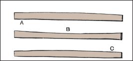
Figure 4—Whitworth Method of Testing Straight-edges
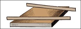
Figure 5—Testing Surface with Straight-edges
Whitworth Method of
Testing Straight-edges
Sir J. Whitworth’s famous method of trueing engineers’ straight-edges should interest any woodworker. Three straight-edges are prepared individually, and each is brought to a moderate state of accuracy; two of them, A and B (Figure 4), are compared with each other by placing them edge to edge, and any irregularities found are removed. The process is then repeated until A and B fit each other perfectly. The third straight-edge, c, now is compared with both A and B, and when it fits both perfectly, then there is no doubt whatsoever that the three are straight. Why this is the case becomes obvious when you remember that though A may be rounded instead of being straight, and B may be hollow sufficiently to make them fit each other perfectly, it is impossible for c to fit both the rounded and the hollow straight-edge.
Testing Surfaces with
Straight-edges
How surfaces are tested for winding with straight-edges is shown by Figure 5, from which it is obvious that if the work has warped ever so slightly a true straight-edge must disclose the fact, as it could not then lie flat on its edge across the work. If the board is in winding, each straight-edge will magnify the error. If the winding is wavy, the edges will touch at certain points, and in other places light will be seen between them and the work. Taking a sight from one straight-edge to the other is another test you can perform.
Rules
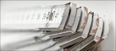
A 2-feet four-fold boxwood rule (Figure 6) is the best for the all-round purposes of the joiner; and for those who can use the slide rule, the tool shown in Figure 7 would be handy. A simple 2-feet two-fold rule (Figure 8) is useful, but the rule with double arch joints shown by Figure 9 will be your best bet. The average worker will find a simple rule preferable to an elaborate one. Figure 10 shows a combined rule and spirit level, the rule joint also being set out to serve as a protractor. This tool may prove useful in special circumstances, but its use as a spirit level is not recommended. It is preferable to have rule and level as two distinct tools.
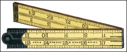
Figure 6—Two-feet Four-fold Rule
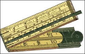
Figure 7—Rule with Brass Slide

Figure 8—Two-feet Two-fold Rule
Dividing a Board with a
Rule
A simple way to divide a board of any width into any number of parts is illustrated by Figure 11. Suppose a board of 9 inches is to be cut into six equal parts; place the 1-foot rule so that its ends touch the opposite edges of board, as shown in Figure 11; draw a line right across, and upon this line mark off from the rule every 2 inches, as 2, 4, 6, etc. Remove the rule, and draw lines parallel with the edge of the board, intersecting with the marks upon the oblique line, thus obtaining six parts, each really 1½ inches wide. The principle of this is simple: 2 inches is the one-sixth part of 1 foot, and whatever be the slant of the rule across the board (and the narrower the board, the greater the slant) each 2-inch mark must denote a one-sixth less than 24 inches length or width is to be divided into eight parts; then as 3 inches is one-eighth of 2 feet, use a 2-foot rule in the same way as before, and mark off at every 3 inches.
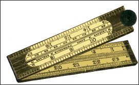
Figure 9—Rule with Double Arch Joints
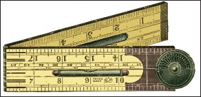
Figure 10—Rule with Spirit Level
Squares and Bevels
Woodworkers constantly use squares for setting out and testing work. The simplest is the try square. A combination try and miter square is shown by Figure 12. This has an iron stock hollowed out to lower its weight to that of a wooden one. This is a useful and cheap tool, very unlikely to get out of truth. A patent adjustable try square is illustrated by Figure 13. The set screw clamps the blade in the stock just where it may be most convenient for awkward work such as puttingbutts, locks, and other fittings on doors and windows. The graduated blade is very useful. The sliding bevel is handy for setting off angles in duplicate, since by using the set screw, the blade can be made to assume any angle with the stock. Figure 14 shows a bevel with a simple ebony stock, and Figure 15 shows one with an ebony stock framed in brass, this protection keeping the edges true for an almost unlimited period. The joiner’s steel square is a mere right angle of steel, sometimes nickel plated, graduated in inches, ¼ inch, and  inch.
inch.
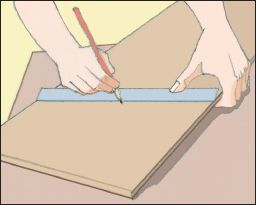
Figure 11—Dividing with Rule
Testing and Correcting Try
square
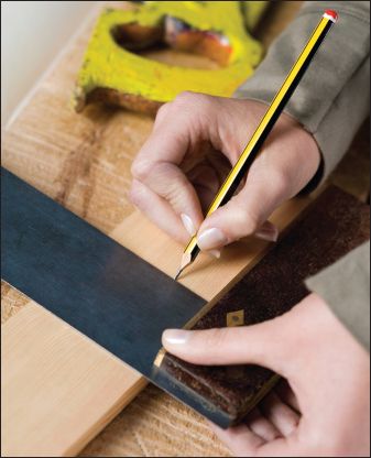
A carpenter’s try square that is thought to be untrue may be tested in the following way. Get a piece of board with an edge that has been proven to be straight, apply the square as shown at A (Figure 16), and draw a line; then turn the square as at B, and if it is true the blade should fit the line; if it is less than a right angle it will be as seen in C and D (Figure 16), and if more than a right angle the defect will be as indicated at E and F (Figure 16). If the blade has moved or has been knocked out of truth through a fall, it should be knocked back into its proper position, and, when true, the rivets should be tightened by careful hammering. If the blade is too fast in the stock to be knocked back, it should be filed true.
Crenellated Squares
A crenellated square has a tongue in which there is a series of crenellations or notches at the graduations. It is especially useful in marking off mortises, though it is available for all other ordinary applications. Three sides of a piece of timber can be set out without moving the work. To use this square, say in marking out a mortise or tenon, take it in the left hand and lay its tongue upon the surface of the work, as in Figure 17. The lower end of the main arm is lowered for 2 inches or so from the surface to get a better purchase, and then an awl, held in the right hand, is placed in a notch at the correct distance from the edge to mark the left-hand edge of the mortise or left hand face of the tenon as the case may be. Then push the square forward, pressing it down gently on the work to make one mark. Next, replace the square and place the awl in another notch at the thickness of the tenon or width of the mortise to make a second mark. Horizontals are drawn by means of the smooth edge of the tongue, as shown in Figure 17.
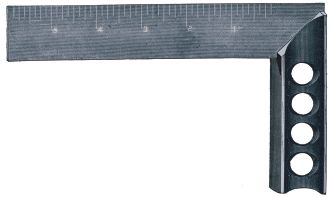
Figure 12—Iron Frame Try Square
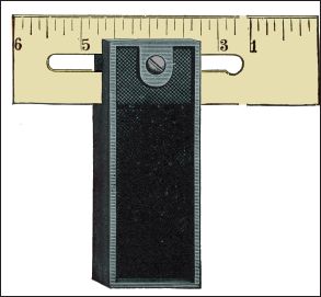
Figure 13—Adjustable Try Square
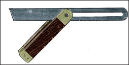
Figure 14—Ordinary Sliding Bevel
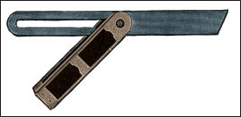
Figure 15—Brass Frame Sliding Bevel
Marking Work for Sawing
The chalk line, pencil and rule, and scribe are all used for marking lines to guide the saw. The chalk line is used for long pieces of timber; pencil and rule for ordinary and roughly approximate work, and lastly, the scribe is used for the most accurate sawing. Lining off a plank or board for ripping, when rough on the edges, is commonly done with a straight-edge or chalk line. If it is square-edged, it can be done by the rule and pencil, which is explained in Figure 18. Hold the rule in your left hand, measuring off on the board the breadth to be ripped, and place your forefinger against the edge to act as a fence. The pencil is held in your right hand and placed at the end of the rule on the board. Then move both hands simultaneously, and you can trace the required line backward or forward, as may be the case. Lines for cross-cutting, when square across or at right angles to the edge, are easily obtained by the square, as long as you keep its blade flat on the board or plank and the stock hard to the edge (see Figure 19). Use the miter square for lines at an angle of 45 degrees to the edge (Figure 20), and for other angles, set and apply the bevel-stock in the same way (see Figure 21). The bevel-stock differs from the square only in that it has a moveable blade and is capable of being adjusted at any desired angle with the stock by using a screw. To use the chalk line method of marking (Figure 22), whiten a piece of fine cord with chalk and pull it taut between two points whose positions are marked to correspond with the end of the cutting line. Then lift the chalk line vertically at or near the center, and as it’s suddenly released, it chalks a perfectly straight and fine line on the timber, and furnishes a correct guide for you to saw. Lines are marked with the timber scribe in such cases as squaring the ends of planed stuff or in marking dovetails and tenons. The saw can then be made to cut close outside the scribed line, allowing for sufficient margin of material to be removed with the plane; or the saw can pass along the scribed line, as in cutting dovetails and tenons, with no after-finish required. In either case, use the scribed line over the pencil-marked one, because the cutting can be done much more accurately in the first case than the latter. Also, when the end of a piece of timber has to be squared with the plane, there is, besides having greater accuracy, much less risk of spalting or breaking out of the grain occurring with scribed lines than with pencil-marked lines.
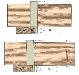
Figure 16—Testing Try Squares in Truth
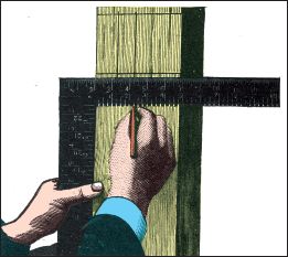
Figure 17—Marking Mortise with Crenellated Square
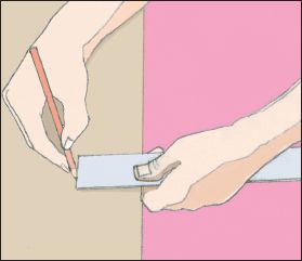
Figure 18—Lining Board with Rule and Pencil
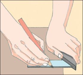
Figure 19—Squaring Line on Board
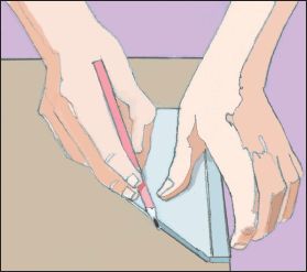
Figure 20—Marking Miter Line on Board
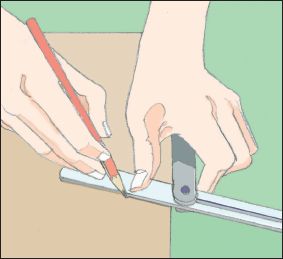
Figure 21—Using Sliding Bevel
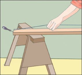
Figure 22—Using Chalk Line
Marking and Cutting
Gauges
The carpenter draws a line at a short distance from, and parallel to, the edge of a board by using a rule and pencil, the method previously described and seen in Figure 18. The use of the pencil or marking gauge is an advantage over this method. Figures 23 and 24 show that there are two ways to make the pencil gauge. It can be made of any hard wood, such as beech. The stem can be round (Figure 23) or square (Figure 24), and the head may be round or octagonal. Make sure the head can slide up and down the stem easily, but without sideplay. The gauge may be made to use up odd pieces of lead pencil, and these should be sharpened (with a chisel) to a wedge-shaped point. Figures 25 and 26 show a pencil gauge made from a broken rule fitted into a block so as to run easily, and secured at any distance (as indicated by the rule’s edge) using a thumbscrew. A represents a block of birch wood, 1½ inches by 1 inch by 1 inch, mortised so it receives the rule. B is a 5-inch length of an ordinary rule, with a slot C just large enough to fit screw D, which is fixed to block A. The thickness of the wood between the washer and the rule should be only 1⅛ inches, to allow a little pliability.
You can make a cutting or scratch gauge similarly by inserting a pin at e, exactly over the first  inch, as that distance is always allowed for. Store-bought marking and cutting gauges are illustrated by Figures 27 to 32. A beechwood pencil gauge is shown by Figure 27, a marking gauge with a steel point by Figure 28, an improved cutting gauge for scribing deep lines in Figure 29, and mortise gauges for scribing mortise holes and tenons by Figures 30 to 32. The mortise gauges are of ebony and brass, the one illustrated1 by Figure 32 having a stem of brass. The ordinary marking gauge is shown in Figure 33.
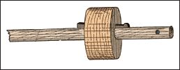
Figure 23—Pencil Gauge with Round Stem

Figure 24—Pencil Gauge with Square Stem
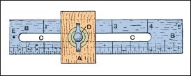
Figure 25—Rule Pencil and Cutting Gauge
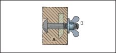
Figure 26—Section through Rule Gauge
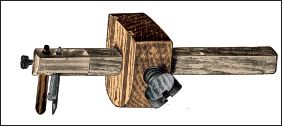
Figure 27—Improved Pencil Gauge
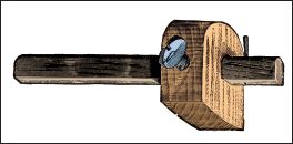
Figure 28—Ordinary Marking Gauge
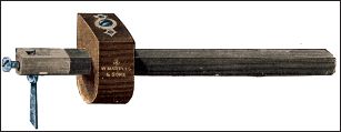
Figure 29—Cutting Gauge
Panel Gauges
A panel gauge (Figure 34) is used to mark a line parallel to the true edge of a panel, or any piece of wood that is too wide for the ordinary gauge to take inches. The stock is of maple, beech, or similar wood. It is 1 inch thick, and has a ⅜-inch by ⅜-inch rebate at the bottom. A mortise is made for the stem to pass through, and another is made at the side for the wedge. The wedge should be made of box-wood or ebony if possible, and is a bare ¼ inches thick. The taper of the mortise in the stock must be made to correspond with it. The stem should be about 2 feet 6 inches long, and may be made of a piece of straight-grained mahogany. It should not fit the mortise too tightly, just so that it can be moved with the hands without tapping, and is held in position by the wedge when set. A piece is dovetailed in the end, as shown, to bring the marking point level with the bottom of the rebate. The stem may be made square if possible, or if the rounded mortise presents a difficulty. Make sure the stock is well finished and nicely polished.
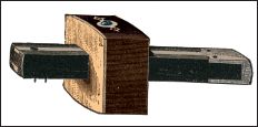
Figure 30—Square Mortise Gauge
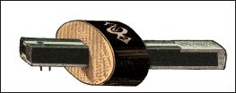
Figure 31—Oval Mortise Gauge

Figure 32—Brass Stem Mortise Gauge
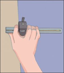
Figure 33—Using Marking Gauge
Compasses, Dividers, and Calipers
Joiners and cabinet workers have a multitude of uses for the above tools, which are of the simplest construction. The ordinary form of wing compasses is such that the wing (the curved side projection) forms one with the left leg, while the right leg has a slot that lets it slide up and down the wing, and the set screw is tightened when the legs need to be fixed at a certain distance apart. For very accurate work, compasses with the sensitive adjustment at side, can be very useful. They are used for stepping off a number of equal distances, for transferring measurements, and for scribing. Calipers are used for measuring diameters of round pins, circular recesses, etc.; for the former purpose use outside calipers and inside calipers for the latter purpose.
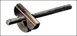
Figure 34—Panel Gauge
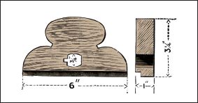
Figures 35 and 36—Elevation and Section of Panel Gauge
Stock
Appliances for Mitering
The technical term miter is applied usually to the angle between any two pieces of wood or molding where they join or intersect, for example the angles in a picture frame. In this instance, the joint would be a true miter—that is to say, it would be 45˚ or half the right angle (90˚) formed by the two inner edges of the frame. Although the term miter is generally understood to apply to a right angle, any angle, acute or obtuse, can also be called a miter.
Miter Blocks
There are various appliances employed in cutting miters, but the simplest is the miter block. Lay the project on the rebate, shown by C (Figure 41), and use the saw kerfs A and B as a guide for the tenon saw. The best form of miter block is made from a piece of dry beech, about 16 inches long, 6 inches wide, and 3 inches thick. Then cut a rebate c to about the size shown in Figure 41. Make sure that the angle is perfectly true. Lines A and B are set out to an angle of 45˚, and then square down the rebate and back of the block. Cut the lines down with a tenon saw, and remember that the accuracy of the saw depends on the value of the finished miters. Figure 42 is a section of the miter block commonly used by joiners. This is simply two pieces of wood planed up true and screwed or nailed together. This plan answers very well, as when it becomes worn and out of truth another can be made inexpensively. The block shown by Figure 43 has a ledge on the bottom as shown; owning to the inward slant the project is more easily held.
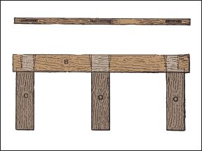
Figures 37 and 38—Frame of Improved Shooting Board

Figure 39—End Elevation of Improved Shooting Board
Miter Box
Figure 44 shows a miter box which serves the same purpose as the block. This is made with three pieces of deal about 1 inch thick, nailed together at the bottom as shown. Miter boxes for heavy work require a strengthening piece on top to hold the sides together (see Figure 45). Sometimes three pieces may be necessary (see Figure 46). Both these illustrations show pieces of molding in position for miter-cutting.

Figure 40—Shooting Board Giving Oblique Planing
Miter Shooting Block
Figures 47 and 48 show a miter shooting block for shooting or planing the edges of objects sawn in the miter block or box. In Figure 47 the bottom piece is of dry red deal, 2 feet 6 inches long, and rebated. For the top piece, select a hard material, such as mahogany or beech, or which-ever you prefer. Make sure it is planed perfectly true, and cut at the ends to a “true miter” (45˚); Then firmly screw it to the bottom piece. It is better to fix the ledger pieces across the bottom, to keep the board from warping. Figure 62 shows that the bottom piece is made of two separate boards.
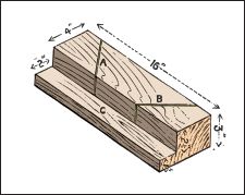
Figure 41—Miter Sawing Block

Figure 42—Section of Miter Block
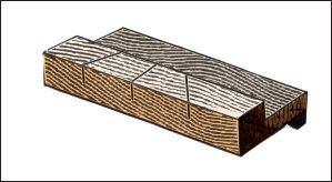
Figure 43—Inclined Miter Sawing Block
Combination Shooting Board
Notwithstanding the large number of patented mitering machines in the market, skilled jointers, when any particularly good piece of work is in hand, still prefer to use the ordinary homemade wooden shoot. The machines, while new and in good condition, are without a doubt faster, but if they are carelessly used, they are apt to get out of order, and then their work is far from satisfactory; while the wood shoot will stand a deal of rough usage, and is also easily repaired, Figure 49 illustrates several improvements on the old form of shoot. A miter-shoot, square-shoot, and joint-shoot are combined in one board, which will prove very handy when you only want to use these appliances occasionally. The shoot consists of a top board of seasoned yellow deal 3 feet by 9 inches by 1½ inches, slot-screwed to an under-frame of teak, made up of the plane bed b, 3 feet by 2¾ inches by 1½ inches, into which are framed three cross rails 2¼ inches by 1 inch flush on the under-side. The center of the top board is the miter-block, a piece of dry oak 2 inches thick cut with two of its sides exactly square with each other, and at an angle of 45˚ with the third. This block, instead of being fixed in the general way, should be mounted on A pivot in its center, as shown at B (Figures 49 and 50), and is capable of adjustment either as a miter-shoot, as shown in the full lines, or as a square-shoot, as indicated by the dotted lines in Figure 49; it is firmly secured in either position by means of three ½-inch by 3-inch square-head screw bolts. Be sure that the grain of the block runs parallel with the plane bed so shrinkage will not alter its shape. The board should be arranged for jointing by removing the miter-block and working the boards against the adjustable stop A. This stop works in an undercut groove, and is secured in any requited position by the screw bolt; the projection at the end prevents the boards from slipping while being planed.
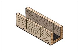
Figure 44—Miter Box
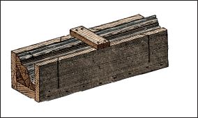
Figure 45—Miter Box with Strengthening Piece
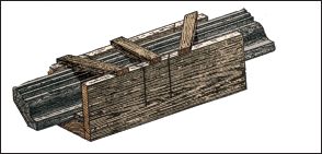
Figure 46—Miter Box with Strengthening Pieces
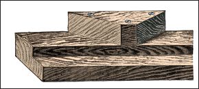
Figure 47—Miter Shooting Block with Solid Base
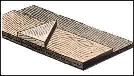
Figure 48—Miter Shooting Block with made-up Base
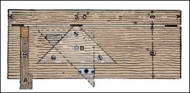
Figure 49—Combination Shooting Board
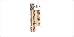
Figure 50—End Elevation of Combination Board
Miter Templates
You will use miter templates constantly as an aid in cutting miters. They are made from a piece of hard wood, in the form shown by Figure 54; it is usually about 4 inches long, 3 inches wide either way, and ½ inch thick. You can make a true miter by planing up true a square block of hard wood, cutting out a rebate b, and on each end make a “true miter” (45˚) as shown. If an ordinary cupboard framing is examined at the junction of the rail with the jambs, it will be seen that each of the molded edges has been mitered as shown in Figure 55. To obtain this miter, you can use the template. Figure 56 and Figure 57 show the template applied to the edge being held by the left hand, while the right guides the chisel A.
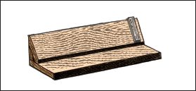
Figure 51—Donkey’s ear Shooting Block
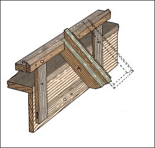
Figure 52—Donkey’s-ear Block for Shooting Wide Surfaces
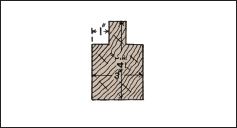
Figure 53—Rest of Donkey’s-ear Block
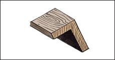
Figure 54—Miter Template
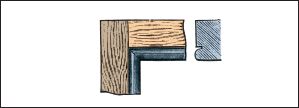
Figure 55—Molding with Mitered Joint

Figure 56—Application of Miter Template
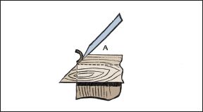
Figure 57—Using Chisel with Miter Template
Spirit Level
The spirit level is used to determine the plane of the horizon—that is the plane forming a right angle to the vertical plane. A frame holds a closed glass tube nearly filled with an-hydrous ether or with a mixture of ether and alcohol. Make sure your spirit level comes with a graduated scale engraved on the glass tube or on a brass or steel rule attached to the frame beside it, so as to mark the position of the bubble, the tube being so shaped that when the level is lying on a flat and horizontal surface the bubble occupies the center of the tube. Many levels have provision for altering the length of the bubble. Figure 58 is a view of an ordinary spirit level, and its construction is made quite clear by the sectional view, Figure 59.
To use the spirit level, apply it to the work twice, reversing it at the second application, and find the mean of the two indications when you are finished. Spirit levels are made in many shapes and sizes, but the method of construction is always the same. A serviceable tool has a narrow shape, about 10 inches long and its greatest breadth being  inches, and diminishing to ½ inch at the ends.

Figure 58—Spirit Level

Figure 59—Section of Spirit Level
The frame is of any hard, tough wood, like box, ebony, lignum-vitae, birch, beech, walnut, or oak. At the back of the tube should be silvering, which shows up the bubble and enables side lights to be dispensed with. The tube is set in plaster-of-paris, and has a brass cover. Store-bought spirit levels are constructed generally in ebony or rosewood, with better qualities having a metal protection for the edges and faces. This will preserve the truth of the instruments for a longer time. A serviceable American level has a mount entirely of steel, which is hexagonal in section, and has rounded ends. Another handy form is the one mounted wholly in brass; this has a revolving protector over the bulb opening, and there is provision for adjustment should the level after a time wear out of truth. A very convenient form of level is the one with a graduated screw slide that allows the fall per foot to be shown at a glance.
