
WHAT IT TAKES
Time: 2 weekends
Skill level: Advanced
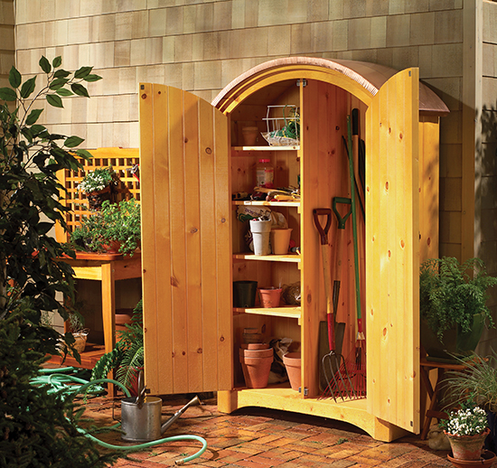
Wouldn’t it be nice to have all your gardening tools and supplies in one handy location? This copper-roofed pine hutch holds long-handled tools like shovels, rakes and hoes on one side, and smaller tools and supplies on shelves on the other side.
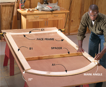
Build the face frame (Photo 3) first and use it as a guide for assembling the doors and cutting the curve on the back panel.
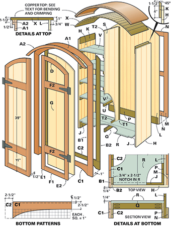
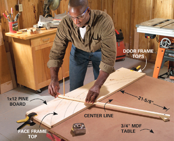
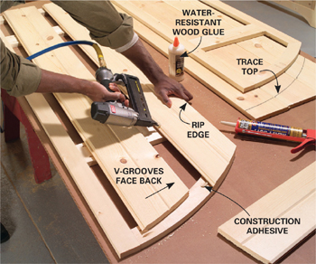
A full sheet of 3/4-in. MDF (medium-density fiberboard) or particleboard set on sawhorses makes a good workbench for this project. Set up for marking the arcs (for the curved pieces) by drawing a center line parallel to the long edge of the sheet. Center a 4-ft. length of 1x12 on the line. Line up the top edge with the edge of the workbench and clamp it. Screw the point of the homemade compass in the center line 21-5/8 in. below the bottom edge of the 1x12 (Photo 1). Draw three arcs for the face frame top and door top pieces (Figure B). Then replace the 1x12 with another 48-in. 1x12 and relocate the screw point (see Figure B). Draw two arcs to outline the 1-1/2-in.-wide curved roof trim molding. Cut out the curves (Photo 2).
Even with careful jigsaw work, you'll need to sand the curves smooth. Use 80-grit sandpaper on a sanding block to even out the curve and remove saw marks. Then sand again with 100- and 120-grit paper. For the best-looking finish, sand all the boards before assembly. Use a random orbital sander or hand-sand with the grain of the wood.
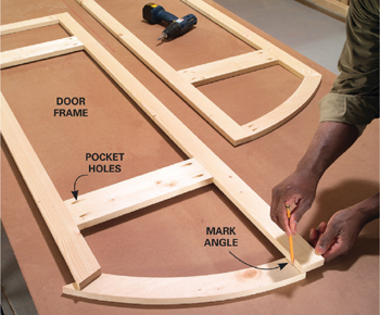
After cutting and sanding the curved pieces, rip the remaining face frame and door trim pieces to width and cut them to length according to Figure A and the Cutting List. Use the pattern to cut the curve on the 39-in.-long 1x6 bottom frame piece (C1). Cut the same curve on the 44-in.-long x 5-in.-wide piece (C2). Use this for the bottom cleat (Photo 5). Assemble the face frames and door frames and the back frame with pocket screws. Photos 3 and 6 show how to mark for the angle cuts where the curved pieces join the straight ones.
Use a miter box to cut angles on the ends of the curved pieces, and steady them by supporting them with one of the scrap concave corners cut from the 1x12. Place the straight edge of the concave scrap against the fence and nestle the curves. Then sight along the blade and adjust the angle to cut along the line. Use this same technique for cutting the angles on the ends of the curved door frame tops (D) as shown in Photo 6.
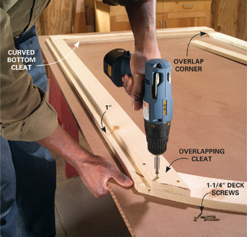
After assembling the face frame, flip it over and screw on the cleats (B2 and C2; Photo 5). The cleats overlap the joints to add strength and serve as a nailing surface for the floorboards and side panels.
Use the completed face frame as a guide to check the fit of the doors as they’re built. The goal is to end up with a 1/8-in. space between the doors and the face frame and between the two doors. Sand or plane them as needed to create an even gap. Build and fit the door frames first. Then use them as a guide to cut out the tongue-and-groove boards that make up the door panels (Photo 7). Rip the groove off the first board in each door panel and then rip the last board to fit. Glue and nail the boards to the frames and then sand the edges flush. A belt sander works great for this task.
The panels for the sides and back are constructed just like the door panels. Rip the tongues and grooves from the outermost boards after figuring out how wide they should be (Photo 8). The exact ripping widths will probably vary between projects, based on the boards that are used. The easiest approach is to temporarily assemble the tongue-and-groove boards, using clamps if needed to draw them tight together. Then mark the panel widths on them, making sure to measure over the panel to remove an equal amount from the outside boards. Rip the outside boards to width. Then assemble the panels. Run a small bead of water-resistant wood glue along the tongue of each board before sliding it into the groove. Clean up any squeezed-out glue right away with a damp cloth. When the glue hardens, the panels will be rigid and strengthen the cabinet. Use construction adhesive to glue the panels to the frames and/or cleats.
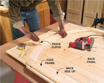
Here are a few special considerations for building the panels. First, use a framing square to make sure the panels are perfectly square before the glue dries. Cut the curve on the back panel after it’s constructed (Photo 9). The beveled top cleat (K) on the side panels (H) is a little tricky. Study Photos 10 and 13 and Figure A to see its location and orientation.
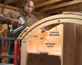
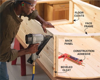
Glue and nail the completed panels and face frame together (Photo 10). Then add the floorboards and center panel (Photo 12). Center the curved molding (A2) and nail it to the top of the face frame. Finally, glue and nail the roof boards along the curve (Photo 13). Start with 1x4s aligned with the ends of the curved molding. Then complete the roof with 1x3s, working from both sides to the center. To make sure everything is square, temporarily tack the 1x4 in place. Then set four of the 1x3s on the roof with their ends perfectly aligned and measure the front overhang to make sure it’s consistent. If the overhang is getting larger or smaller, move the back end of the 1x4 down or up, respectively, to correct the problem.
When the cabinet is complete, tip it on its back to install the doors (Photo 14). Use any strong gate-type hinge. Just make sure to leave an even space around the perimeter of the doors and between them. Use a belt sander to trim tight spots.
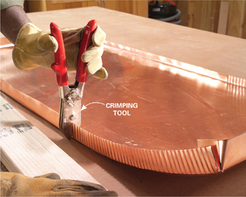
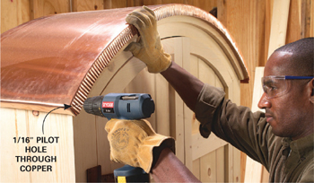
Start with a 24-in. x 60-in. piece of 16-oz. copper sheeting. Screw down a 2x4 frame on the bench top to provide clearance for bending down the edges. Start by snipping the corners of the copper with tin snips (Photo 15). Then hand-bend the edges of the sheet down over the 2x4s. The last step is to crimp the edges with the five-blade downspout crimper to curve the sheet (Photo 16). Keep the crimps parallel by aligning one of the crimping blades in the previously made crimp before squeezing it. Crimp about 12 in. on the front. Then crimp 24 in. on the back to even up the curve. Continue alternating until the end. Adjust the arch for an exact fit once the copper is back on top of the cabinet. Hold off on nailing the copper in place (Photo 17) until after a finish has been applied to the hutch.
Since the hutch is pine and will rot quickly if left unprotected outdoors, apply a durable finish. This hutch has an oil stain and three coats of spar varnish. Be sure to seal the bottom edges thoroughly. If putting the hutch in a wet location, install metal or plastic feet on all four corners to elevate it slightly. Setting the hutch on an uneven surface can cause the doors to bind or fit poorly. Shim under the cabinet to level it, if needed.
KEY |
PCS. |
SIZE & DESCRIPTION |
Face frame |
|
|
A1, D |
1 |
48" x 3/4" x 11-1/4" (curved frame and door tops) |
A2 |
1 |
48" x 3/4" x 11-1/4" (curved molding; cut curve and ends) |
B1 |
2 |
68" x 3/4" x 3-1/2" (sides)* |
B2 |
2 |
66" x 3/4" x 2-1/2" (side cleats)* |
C1 |
1 |
39" x 3/4" x 5-1/2" (bottom; cut curve to pattern) |
C2 |
1 |
44" x 3/4" x 5" (bottom cleat; cut curve to pattern) |
Doors |
|
|
D |
2 |
Curved tops (cut from ”door top” above) |
E1 |
2 |
68-5/8" x 3/4" x 2-1/4" (door sides)* |
E2 |
2 |
61" x 3/4" x 2-1/4" (door sides)* |
F1 |
2 |
14-13/16" x 3/4" x 2-1/4" (door bottom rail); see Figure B |
F2 |
4 |
14-13/16" x 3/4" x 4" (intermediate rails) |
G |
6 |
72" t&g 1x8 (door panels); cut to fit |
Sides |
|
|
H |
6 |
68-1/4" t&g 1x8 (19-1/2" x 68-1/4" side panels) |
J |
2 |
5" x 3/4" x 17-1/4" (bottom cleats) |
K |
2 |
5-1/2" x 3/4" x 17-1/4" (top cleats; bevel top to 45 degrees) |
Back |
|
|
L |
7 |
78" t&g 1x8 (44" x 78" back panel; cut top curve) |
M |
2 |
3-1/2" x 3/4" x 68" (frame sides) |
N |
3 |
3-1/2" x 3/4" x 37" (frame crosspiece) |
P |
1 |
5" x 3/4" x 42-1/2" (bottom cleat) |
Interior parts |
|
|
Q |
1 |
2" x 3/4" x 16-1/2" (floor crosspiece) |
R |
2 |
9" x 3/4" x 44" (floorboards) |
S |
3 |
72" t&g 1x8 (17-1/4" x 72" center panel) |
T1 |
1 |
3/4" x 3/4" x 72" (center panel cleats) |
T2 |
2 |
3/4" x 3/4" x 17-1/4" (center panel cleats) |
U |
8 |
1-1/2" x 3/4" x 17-1/4" (shelf cleats) |
V |
8 |
8-5/8" x 3/4" x 21-5/8" (shelf boards) |
W |
3 |
3-1/2" x 3/4" x 21-1/2" (roof boards) |
X |
18 |
2-1/2" x 3/4" x 21-1/2" (roof boards) |
*Cut top angles at 22 degrees.
Materials list
ITEM |
QTY. |
1x2 x 8' pine |
3 |
1x3 x 8' pine |
9 |
1x4 x 6' pine |
4 |
1x4 x 8' pine |
3 |
1x6 x 6' pine |
4 |
1x10 x 8' pine |
3 |
1x12 x 8' pine |
1 |
1x8 x 6' t&g pine |
15 |
1x8 x 8' t&g pine |
7 |
8" gate hinges |
4 |
Latch |
1 |
Tubes of construction adhesive |
2 |
Magnetic catches |
4 |
Water-resistant wood glue |
|
1-1/4" finish nails |
|
Copper or brass weatherstrip nails |
|
Pocket screws and jig |
|
2' x 5' 16-oz. copper sheet (Available from roofing or sheet metal suppliers) |
|
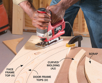
2
Saw out the curved pieces with a jigsaw. Use the pattern to draw the curve on the face frame bottom (C1) and saw it out.
3
Cut the side pieces (B1) to length with 22-degree angles on the tops. Snug the face frame sides to the bottom (C1) and to a 39-in.-long spacer and clamp them to the table. Scribe lines on the curved top (A1) and cut off the ends.
4
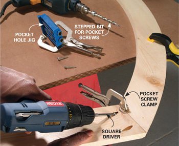
Drill pocket holes on the back side of the face frame pieces with a pocket hole jig. Glue the joints and connect them with pocket screws.
5
Cut backing cleats (B2 and C2) that overlap the face frame joints (Figure A, parts A1, B1 and C1). Predrill and screw them to the back of the face frame.
6
Assemble the door frame with pocket screws as shown. Then cut the curved top (D) in half and cut angles on the ends to fit. Attach them with pocket screws as well. Place the assembled door frames in the face frame to check the fit. Plane and sand as needed to allow a 1/8-in. space around and between the door frames.
7
Temporarily assemble the door panels and center the frames over them. Mark the bottom, sides and top. Rip the sides and cut the top curve. Cut the bottoms 1/4 in. shorter than marked. Then glue and nail the boards together with wood glue and fasten them to the frame with construction adhesive.
8
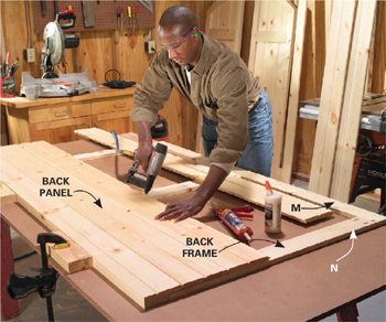
Assemble the back frame (M and N) with pocket screws. Glue and nail tongue-and-groove boards to it to form the cabinet back. Rip the first and last boards to fit.
10
Assemble the side panels (Figure A). Then glue and nail the side panels to the back panel and the face frame.
11
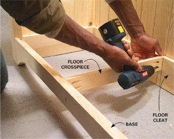
Screw in the crosspiece (Q) with pocket screws to support the floorboards. Notch the first floorboard (R) to fit around the face frame and glue and nail it down. Cut the back floorboard to fit and nail it in.
12
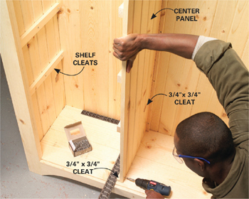
Glue and nail together the center divider and attach it to the bottom and back with cleats (T1 and T2) and screws. Attach the top to the ceiling boards after they’re installed (Photo 13).
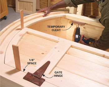
14
Screw temporary cleats to the back of the face frame to support the doors. Set the doors in place and trim them if necessary to allow 1/8-in. clearance all around. Predrill for hinge screws and screw on the door hinges and hardware.
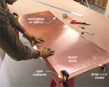
15
Center the 24-in.-wide copper sheet over the cabinet top with a 1-1/2-in. overhang in front. Mark along the back, front and ends with a permanent marker. Add 1-1/2 in. to the ends and cut the copper sheet to length with tin snips. Snip the corners as shown. Bend the front, back and ends down over the 2x4 frame.