The decel maneuver left little room for error. Unlike in other jets, Habus didn’t have the option to change throttle settings at random or add and subtract drag devices to modify their rate of descent. The instant the throttles were brought out of afterburner to start down from seventy-eight thousand feet, the bottom-out point of the decel was basically set in stone. It was necessary to manage the SR-71’s engines and inlets during the decel in a precise configuration to preclude unstarts, compressor stalls, and engine flame-outs.
It was difficult for air-traffic controllers in the United States to understand our descent problem. They were accustomed to telling high-altitude aircraft when to descend, increase or decrease their rate of descent, or turn to another heading, all to avoid a conflict with another aircraft in the vicinity. We were not able to do any of that! When the controller was screaming at us over the radio, it was difficult for him to accept the words, “Unable to comply.” Crew members were periodically sent to several ATC facilities to brief and educate controllers on our descent profile and emphasize the fact that crews could not deviate from their descent procedures without the potential for bad consequences.
About a minute or so before the start-descent point, the RSO began reading the following checklist:
1. ANS distance on HSI—DP/TURN
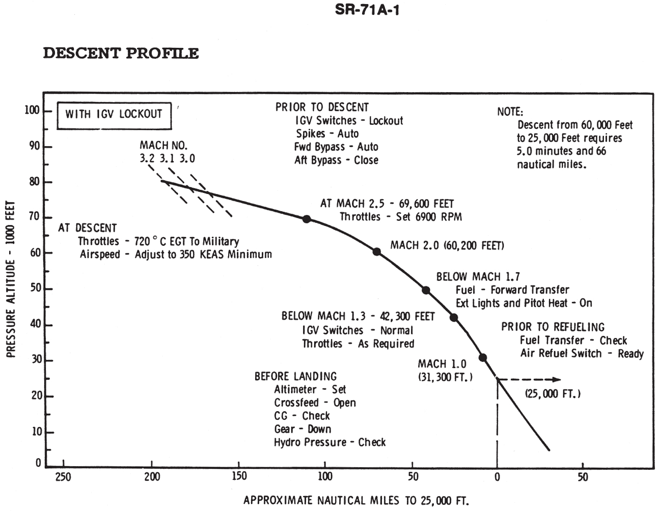
The RSO referenced the descent chart (see figure 14, Descent Profile) to include any changes to the planned descent point. A normal descent was planned for a constant 350 KEAS with no wind conditions, standard day temp devs, down to a level-off altitude of twenty-five thousand feet, and a normal aircraft configuration. If any of these factors changed, the RSO needed to make adjustments to the start-descent point. To ensure there was no confusion, the RSO coordinated with the pilot on any variables that he included in his calculations. A standard decel from seventy-eight thousand feet down to twenty-five thousand feet took around nine minutes and covered approximately 165 nautical miles.
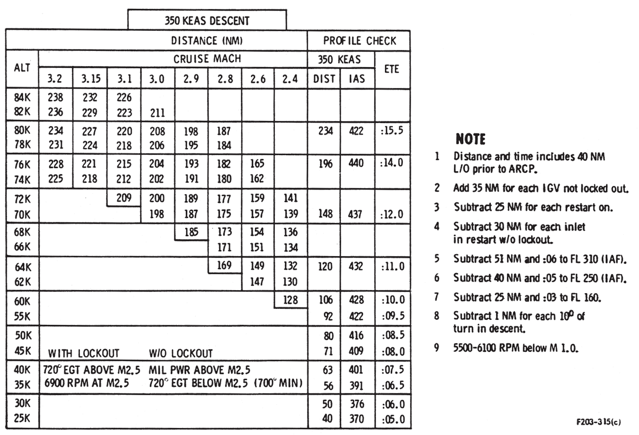
Figure 14
Prior to starting down, the RSO established ranging with the lead tanker, making sure the tankers were there. Crews monitored the radio in case the tanker had something important to report or had to move the ARCP because of bad weather.
After discussing the agreed-upon start-descent point, the crew members double-checked that each of their cockpits displayed the same ANS distance to the next DP and waited for the appropriate distance in the DME window to start the decel. The pilot stated, “Start-descent back set 103 miles from DP-19.”
2. IGV switches—LOCKOUT
The crew checked that the IGV switches were still in LOCKOUT from the accel. This setting prevented the IGVs from shifting to axial as the throttles were retarded. If the LOCKOUT feature was known to be inoperative, the RSO had to adjust the start-descent point by adding another thirty-five nautical miles to the start-descent point for each IGV not locked out. The pilot stated, “IGVs locked out.”
3. LN2 quantity—Checked
The pilot checked to make sure there was sufficient liquid nitrogen remaining to complete the descent in a normal manner. During the rapid descent, the SR-71 relied on fuel-tank pressurization provided by the gaseous nitrogen to keep the six main fuel tanks from collapsing. If you’ve ever sealed up an empty plastic bottle and watched it during a descent on an airliner, you’ll see the plastic bottle collapse around itself, and that’s only descending from a cabin pressure of around eight thousand feet.
To prevent the tanks from collapsing, a fuel-tank suction-relief valve was located in the nose wheelwell and opened when slight negative tank pressurization was sensed. To maintain structural safety, pilots had to limit the SR-71’s rate of descent so that the fuel-tank pressure gauge did not read less than 0.5 psi.
The emergency procedure for low nitrogen pressure required that the crew loiter subsonic at forty thousand feet until pressures were positive. Hopefully, this relieved the negative pressure inside the tanks and cooled the fuel sufficiently to prevent potential ignition of volatile fuel vapors. It was necessary to maintain a shallow rate of descent all the way to landing. Fortunately, the nitrogen fuel-tank pressurization system was relatively problem free. The pilot confirmed, “LN2 checked.”
4. Inlets—AUTO and CLOSE
The crew ensured that the inlets were still in the AUTO position and the aft bypass switch was placed in the CLOSE position. If crews had manual inlets, at this point they referred to the manual inlet descent profile chart to determine the configuration for the decel. The RSO would also have to adjust the start-descent point for manual inlets. The pilot stated, “Inlets auto and closed.”
5. INS altitude—Update
The RSO updated the altitude to the after-descent condition: air refueling or landing. He confirmed, “INS updated.”
1. If manual inlet(s), RESTART(S)—ON
If flying with manual inlet(s), the pilot turned the respective RESTART switch(es) to ON at this point. Otherwise he stated, “Auto inlets.”
2. Throttles—720 degrees C. EGT to Military
When the aircraft arrived at the computed start-descent point, the pilot slowly retarded both throttles to min-AB, paused momentarily, then pulled them back further to drop down into the full-military position. He stated, “Throttles 720 degrees (or military).”
3. Airspeed—365 KEAS (350 min)
As the KEAS began to decrease, the pilot slowly rolled the pitch wheel forward and intercepted a speed between 350 and 365 KEAS for the decel. Since 350 KEAS was the minimum airspeed, 365 KEAS provided an extra margin of safety from unstarts, engine compressor-stalls, or flame-outs. As the airspeed approached 365 KEAS, the KEAS HOLD function on the autopilot was engaged. The autopilot then controlled the airspeed by varying the pitch of the aircraft. The descent profile required the pilot to keep the throttles between 720 degrees Celsius on the exhaust gas temperature gauge and full military power. The pilot stated, “Airspeed 365 KEAS.”
Engine flame-outs in the SR-71 were most likely to occur during the decel. Even holding the decel parameters perfectly, the engines (one or both) would occasionally compressor-stall and flame out for no apparent reason. A few select Habus have the dubious distinction of logging glider time in the SR-71 by having both engines flame out during the decel. In most instances, the Habus were not successful in obtaining airstarts at high altitudes and high Mach numbers. Successful airstarts generally occurred at Mach 1.7 or below.
4. Tank pressure—Monitor
Throughout the decel, the pilot monitored the fuel-tank pressure to make sure it was reading a positive value and confirmed, “Tank pressure monitoring.”
5. Throttles—6,900 rpm
Passing through Mach 2.5, the pilot slowly retarded both throttles until each gauge read 6,900 rpm. Between Mach 2.5 and 1.3, the pilot had to continually advance the throttles slightly to maintain 6,900 rpm. The pilot confirmed, “Throttles 6,900.”
6. IFF Mode C—As briefed
The IFF set was turned on to enable air-traffic control to pick up the SR-71 on radar and display its altitude for separation from other traffic. The RSO said, “Mode C on.”
7. DEF systems—As required
The DEF systems were turned off if descending to land or placed on standby if air refueling for another hot leg. Since the SR-71 in this example was descending for landing, the RSO stated, “DEF systems off.”
8. Forward xfer—On
To achieve a favorable subsonic forward center of gravity, the pilot turned on the forward transfer switch to move fuel into tank one. After a quick check of tank one quantity to make sure it was receiving fuel, the pilot stated, “Forward transfer on.”
9. Pitot heat—ON
The pilot turned on the pitot heat for all descents just in case the aircraft encountered icing conditions. He confirmed, “Pitot heat on.”
10. Exterior lights—On
Turning the anticollision lights and taillight on, the pilot stated, “Exterior lights on.”
11. Inlet controls—Checked
The pilot checked to make sure the spike and forward bypass controls were in AUTO and the aft bypass doors were set in the CLOSE position. He then stated, “Inlets auto and closed.”
12. IGV switches—NORMAL
Placing the inlet guide vane switches to NORMAL restored the engines to maximum thrust capability. The IGVs shifted to axial and the IGV lights illuminated if the rpm was above 5,500 rpm. The pilot confirmed, “IGVs normal.”
13. Throttles—As required
After reaching Mach 1.3, the pilot could finally place the throttles anywhere to adjust the descent profile as necessary. Once the plane was subsonic, the pilot maintained Mach 0.9 for cruise, disengaged the KEAS HOLD function on the autopilot, and leveled off by using either the autopilot pitch wheel or hand-flying the plane. The descent was fairly steep and required a two-thousand-foot lead point to level off. The pilot stated, “Throttles as required.”
14. Forward xfer—OFF
Forward fuel transfer was turned off once the CG gauge read seventeen to twenty-two percent, and the pilot stated, “Forward transfer off.”
15. Crossfeed—Set
The fuel crossfeed was selected OPEN if an immediate approach to landing were being accomplished, if tanks five and six were empty, or if the FUEL QTY LOW light illuminated. The pilot said, “Crossfeed open (or closed).”
At this point, the SR-71 would be around forty nautical miles from the ARCP and one thousand feet below the refueling altitude. From here, the process merely repeated the cold air refueling rendezvous accomplished in Chapter 12. We will now continue the descent for the final landing.
Just prior to the final descent for home, the RSO gave his final “ops normal” call over the HF radio. Then he made a quick radio call to Momma Control to check the current weather conditions and let the det know the status of the aircraft. If the mission was not “normal,” the RSO transmitted a series of coded letters over the HF radio to alert everyone monitoring the frequency to the problem.