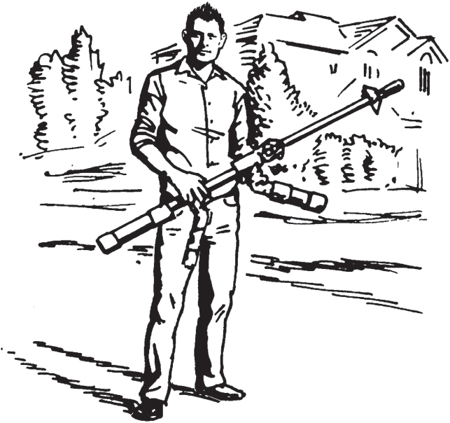
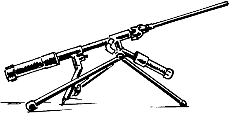
If you have made it this far, congratulations! You are on your way to becoming a Master Tinkerer. This last project requires all the skill sets you have garnered throughout the year of weekend projects. It is now time to create an AK 47–style Handheld Rocket Rifle.
52
HANDHELD ROCKET RIFLE
SAFETY KEY:
+ Adult supervision: This project can be very dangerous due to the compressed air, so only use with adult supervision—and only outside and away from homes and buildings. Do not fire at pedestrians.
SKILL LEVEL:
EASY
INTERMEDIATE
ADVANCED
APPROXIMATE TIME:
6 hours
LET’S BEGIN
Because of the number of pieces needed for this project, we have helped you out if you want to order them from Home Depot online or at the store. We have included detailed part descriptions so you can have it all prepared.
Refer to the legend to see all the pieces and where they fit together.

LABEL |
|
QUANTITY |
|
DESCRIPTION |
A |
|
2 |
|
2 in. PVC cap |
B |
|
2pcs × 9″ |
|
2 in. × 10 ft. PVC Schedule 40 DWV pipe |
C |
|
2 |
|
2 in. PVC Schedule 40 pressure slip × slip coupling |
D |
|
2 |
|
2 in. × 1½ in. PVC Schedule 40 pressure spigot × slip bushing |
E |
|
2 |
|
1½ in. × 1 in. PVC spigot × FIPT bushing |
F |
|
2 |
|
1 in. close PVC |
G |
|
2 |
|
1 in. PVC Schedule 40 pressure S × FPT female adapter |
H |
|
5pcs × 2.25″ |
|
1 in. × 10 ft. PVC Schedule 40 plain-end pipe |
I |
|
2 |
|
|
J |
|
2 |
|
1 in. PVC slip × slip × slip tee |
K |
|
1pc × 9″ |
|
Use leftover 1-inch pipe from “H” |
L |
|
1pc × 3″ |
|
Use leftover 1-inch pipe from “H” |
M |
|
1 |
|
¾ in. × 1 in. PVC pressure S × MPT adapter |
N |
|
1 |
|
¾ in. Sch. 40 PVC FPT × FPT threaded ball valve |
O |
|
1 |
|
¾ in. × close PVC riser |
P |
|
1 |
|
¾ in. PVC threaded cap |
Q |
|
1 |
|
¼ in. NPTM industrial plug |
R |
|
1 |
|
Gardner Bender 3/6 amp momentary-contact pushbutton switch |
S |
|
1 |
|
|
T |
|
1pc × 17″ |
|
Doorbell wire or similar insulated wire |
U |
|
1pc × 17″ |
|
5/16 in. OD × 3/16 in. ID × 20 ft. clear PVC tubing |
V |
|
1 |
|
1 in. PVC slip × MPT male adapter |
W |
|
1 |
|
Rain Bird 150 psi 1 in. in-line solenoid valve |
X |
|
1 |
|
1 in. × ½ in. PVC Schedule 40 pressure MIPT × FIPT |
|
|
Bushing model # 439-130HC store SKU # 796841 |
||
Y |
|
1 |
|
½ in. PVC schedule 40 pressure MIPT × slip male |
Z |
|
1pc × 24″ |
|
½ in. × 10 ft. PVC schedule 40 plain end pipe |
AA |
|
1 |
|
1¼ in. PVC Schedule 40 pressure 90-degree slip × FPT female adapter elbow |
BB |
|
1 |
|
1¼ in. PVC schedule 40 pressure slip × MIPT male adapter |
CC |
|
1 |
|
1¼ in. PVC plug |
ADDITIONAL ITEMS NEEDED:
From Amazon.com
DD |
|
1 |
|
Fully insulated 9V battery snap connectors |
|||
EE |
|
1 |
|
9-volt battery |
|||
Primer & Cement |
Oatey 8 oz. Handy Pack Purple |
||||||
Primer and Solvent Cement |
|
||||||
Air compressor |
|
||||||
OPTIONAL:
2–4 colors camouflage spray paint
1 can shellac finish and sealer
PVC PIPE ASSEMBLY
You can buy whole lengths of pipe, or just two-foot lengths of PVC pipe. Either will work.
1. 2″ pipe: Cut two pieces to lengths of nine inches each.
2. 1″ pipe: Cut five pieces to lengths of 2.25 inches each.
3. Cut one piece to a length of nine inches.
4. Cut one piece to a length of three inches.
5. Half-inch pipe: Cut one piece to a length of twenty-four inches.
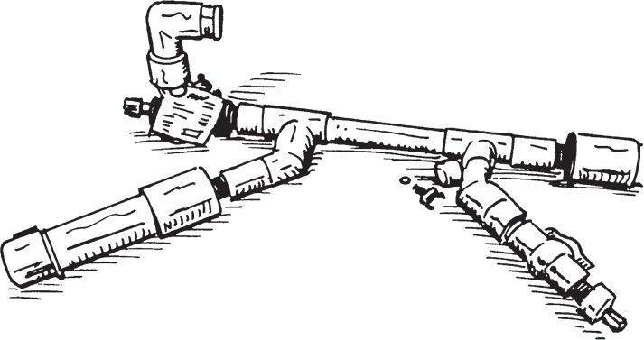
At this point you should be able to “dry fit” the entire rocket launcher together to check fittings. Use the instructional diagram as depicted in the expanded-view diagram included herein. Remember that the “dry fit” is necessary before solidifying your launcher with glue.
![]() WARNING:
WARNING:
Do not pressurize!
NOTE: For cutting pipe, you can use a hacksaw or PVC cutting tool. Power tools are an option but can be dangerous and should not be used without adequate training.
GLUING TOGETHER
NOTE: Read and follow instructions on the labels of your purple primer and PVC cement cans.
1. Use purple primer on all surfaces that would be in contact, and let it dry for about ten minutes before applying PVC cement.
2. When all primer has dried, glue the parts together by applying a coating of PVC cement to both parts of the connection, and when connecting, twist them about a quarter-inch turn to ensure good coverage, and push fully together.
NOTE: Only work on one connection at a time, and work quickly. PVC cement begins to set fairly rapidly, and any delay may result in a failed connection.
3. Glue all parts together as depicted in the expanded-view diagram. The threaded connections should not be glued.
4. Allow at least three hours for cement to cure before pressure testing.
ASSEMBLE
1. Drill a half-inch hole in the top of cap “P” for the pneumatic adapter.
2. You can tap the hole in cap “P” or just use the pneumatic plug “Q” to self-tap. Add thread tape to the threads, and screw down snugly. Do not overtighten because the connection may weaken and fail.
3. Add thread tape to any male-threaded connections (e.g., threaded risers) and screw together tightly with their associated parts. Make the connections airtight. Tools to help tighten may be required.
ELECTRICAL
1. Drill a 5⁄16-inch hole in the side of cap “S.” When attached, this hole will be on the bottom of the trigger. You may choose to grind down the bottom rim of the cap so it fits snugly on the handle of the launcher later when it gets glued on.
2. Also, drill a half-inch hole in the top of cap “S” just large enough for the button of the trigger switch to protrude from.
3. Drill a 5⁄16-inch hole in the middle/top of end plug “CC.”
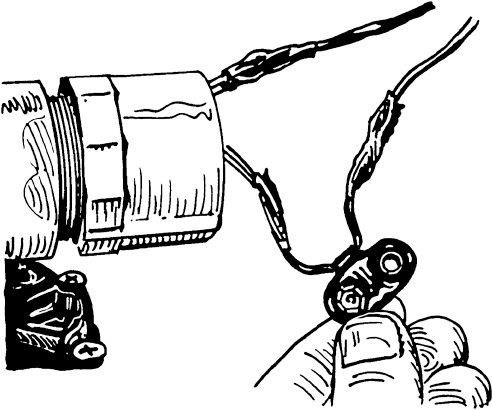
4. Attach wires labeled “T” to the following: snap connector “EE,” sprinkler valve “W,” and momentary switch “R” as depicted here.
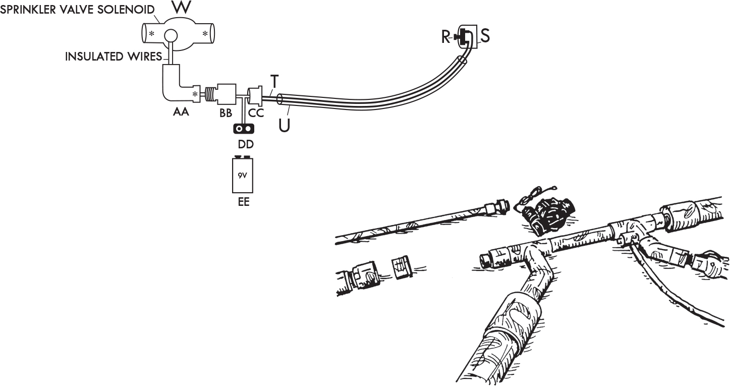
NOTE: To connect wires, the ends will need to be stripped of outer insulation and twisted together with the connecting wire, and any exposed wire needs to be covered with electrical tape to prevent electrical shorting on other parts of the system.
5. Connect nine-volt battery “DD” to snap connector “EE,” and push trigger button “R” to test the connection. If connected properly, you will hear the sprinkler valve solenoid “W” clicking open and closed.
FINISHING
1. Pressure test the system. Attach an air hose from your air compressor and open the ball valve “N” to allow air to flow into the system. I recommend starting around 30 psi and slowly adding pressure, stopping to listen for leaks at regular intervals. Pressing the trigger switch “R” should open the valve and release all the air in the system. Do this on a regular basis to test the electrical connections. Do not exceed 135 psi.
2. As a final test you can close the ball valve “N,” disconnect the air hose so that your launcher is portable, and test-fire in a safe area.
3. Hot-glue the trigger cap “S” to handle pieces “J” and “L” and allow five minutes to cool.
4. If painting the system is desired, use tape and/or masking paper to cover parts of the system you don’t want painted, e.g., valve handles, pneumatic plug, sprinkler valve, trigger button, etc.
5. If possible, hang entire system from one single point, e.g., plug “Q,” and spray paint as desired. Try a camouflage look or experiment with different colors and several coats of paint to give it the look you want.
6. Go above and beyond by adding a coat of finish to give the rocket launcher a professional sheen and help protect the paint.
7. Let dry for about two hours. Your system is finished!
