The focus now shifts to a discussion of three-dimensional symmetries. Attention is restricted mostly to the symmetries of the five regular solids. The chapter and text conclude with a discussion of some recent discoveries in group theory.
As was mentioned above, the last of the thirteen books that comprise Euclid’s famed The Elements is devoted to the three-dimensional analogs of the regular polygons. These highly symmetric solids are aesthetically pleasing to the eye; they have been used as alternative dice in popular games and also as decorations. They have also proved useful to engineers and scientists.
Our discussion must begin with some definitions. A polyhedron is a solid body of finite extent whose surface consists of several polygons, called faces. The sides and vertices of these polygonal faces are respectively the edges and vertices of the polyhedron. The vertices, edges, and faces of a polyhedron are collectively referred to as its cells.
A regular polyhedron is a polyhedron whose cells satisfy the following constraints:
1.All the faces are the same regular polygon;
2.All the vertices are equivalent in the sense that for any two vertices in positions u and v there is a rotation of the solid that replaces the vertex at u with the vertex at v and also replaces all the edges emanating from u with the edges emanating from v.
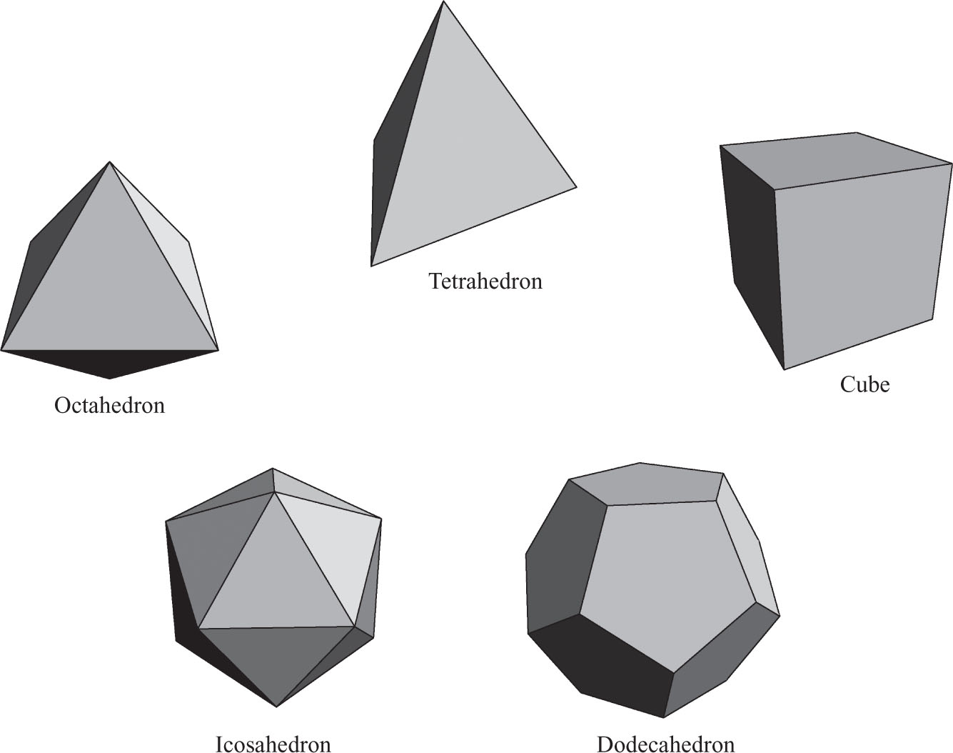
As proved by Euclid in the third century BC, there are five regular polyhedra (see Figure 7.1). However, it is commonly accepted that the Pythagorean school which was active in Greece in the fifth century BC was already aware of all five regular solids two hundred years earlier. The cube, tetrahedron, and octahedron are natural structures and were probably independently constructed in many cultures several millennia ago. The dodecahedron and icosahedron are much less obvious. Theaetetus (415?–369? BC) is credited with being the first mathematician to formally prove their existence.
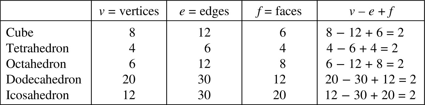
The easiest regular solid to visualize is of course the cube whose faces consist of six congruent squares. It has 12 edges and 8 vertices. Almost as immediate as the cube is the tetrahedron, a triangle-based pyramid, whose faces consist of four equilateral triangles. It has 6 edges and 4 vertices. The octahedron, a double square-based pyramid, has 8 equilateral triangles as its faces. It has 12 edges and 6 vertices. The dodecahedron has 12 regular pentagons as its faces, 30 edges and 20 vertices. The icosahedron has 20 equilateral triangles as its faces, 30 edges and 12 vertices. These counts are tallied in Table 7.1.
Table 7.1: Cell counts for the Platonic solids.
The rightmost column of this table indicates that these counts are subject to a very simple and surprising relationship which actually holds for all polyhedra and not just for the regular ones.
Theorem 7.1.1 (Euler’s Equation). For any polyhedron

This equation is named after its discoverer, the Swiss mathematician Leonhard Euler (1707–1783), who was the most prolific mathematician of all time. The discovery of this equation initiated a flourishing branch of mathematics now known as topology.
The Greeks also discovered another class of highly symmetrical and intriguing polyhedra. A polyhedron is said to be semiregular if
1.All the faces are regular polygons;
2.All the vertices are equivalent in the sense that for any two vertices in positions u and v there is a rotation of the solid that replaces the vertex at u with the vertex at v and also replaces all the edges emanating from u with the edges emanating from v.
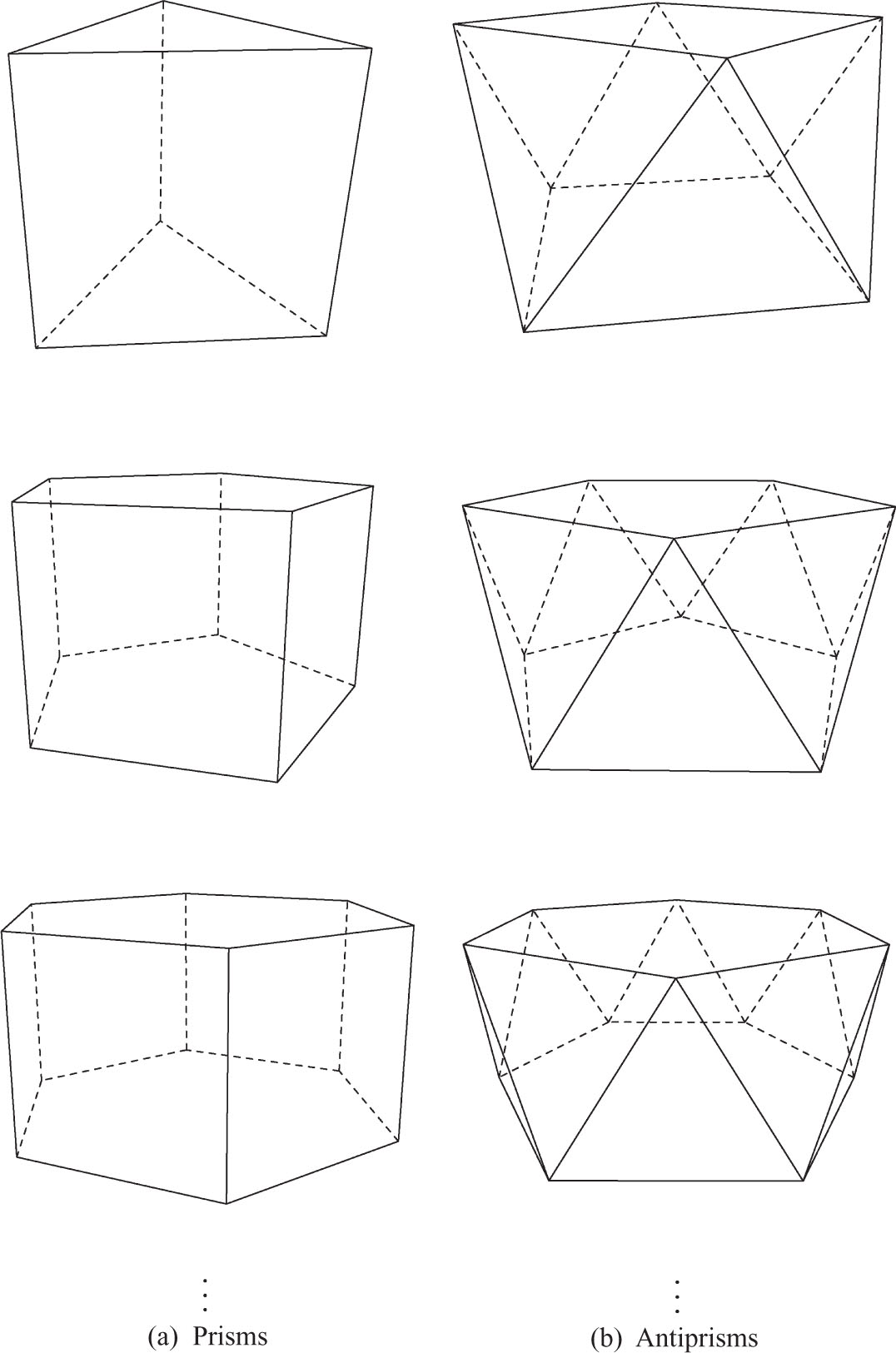
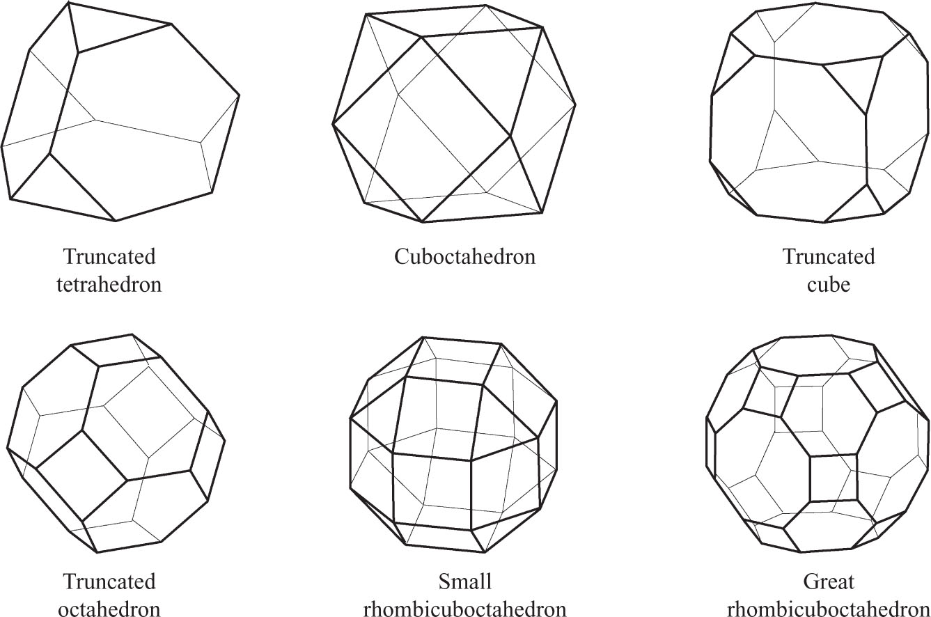
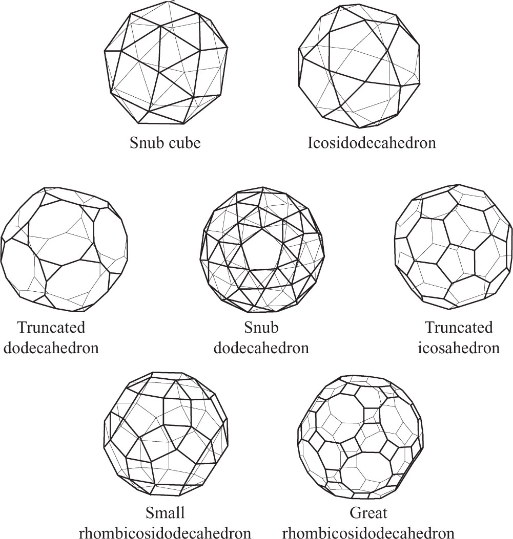
The definition of a semiregular solid differs from that of a regular one only in that the faces need not all be the same regular polygon. These solids can be divided into three classes of which two contain an infinite number, while the third has only 13 members. These are called, respectively, the prisms (Figure 7.2a), the antiprisms (Figure 7.2b), and the Archimedean solids (Figures 7.3, 7.4).
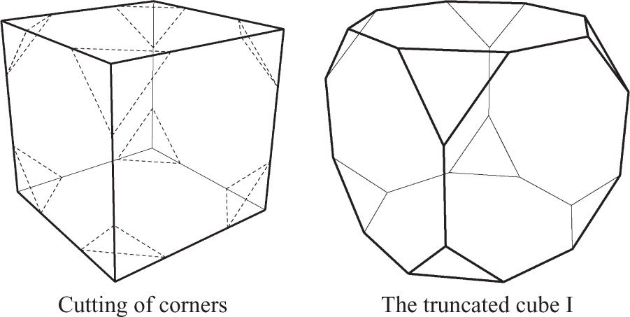
While some semiregular polyhedra were mentioned by Plato (427-347 BC), their first serious study is commonly attributed to Archimedes (287-212 BC) who is said to have found all of those displayed in Figures 7.2–7.4 and to have demonstrated that no others exist. His work on this topic was lost and it was Johannes Kepler (1571–1630) who reconstructed all the Archimedean polyhedra and discussed their relation to the regular ones. It turns out that some of the Archimedean polyhedra can be derived by truncating the corners of the regular solids. This process is demonstrated here for the cube. In this description the cells of the original cube are referred to as the old cells and to those of the derived solid as new ones.
Truncated Cube I. All the corners of the cube are cut so that the (central) portion of the old edge that remains has a length which equals that of the edge of the new triangular face created by the truncation process (Figure 7.5). There are 24 new vertices, two for each of the old edges. Each of the 8 old vertices contributes 3 new edges, and there are also the 12 remnants of the old edges. These add up to a total of 36 new edges. Each of the 6 old square faces has been trimmed down to an octagon and the truncation of each of the 8 of the cube’s corners has left a triangular face. Hence this solid has a total of 6 + 8 = 14 faces. Note that, as predicted by Euler’s Theorem,

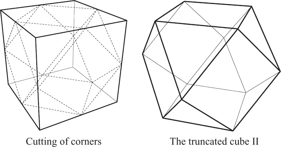
Truncated Cube II. All the corners of the cube are cut off in such a manner that the cutting planes meet at the midpoints of the old edges (Figure 7.6). There are 12 new vertices, one for each of the old edges. Each of the 8 old vertices contributes 3 new edges, for a total of 24. Each of the 6 old square faces has been trimmed down to a smaller new square face and each of the 8 truncated corners has left a new triangular face, for a total of 6 + 8 = 14 new faces. Once again,

in agreement with Euler’s Theorem.
The prisms and antiprisms of Figure 7.2 are offered as further examples of non-regular solids for which Euler’s equation holds. Their cell counts satisfy the respective equations

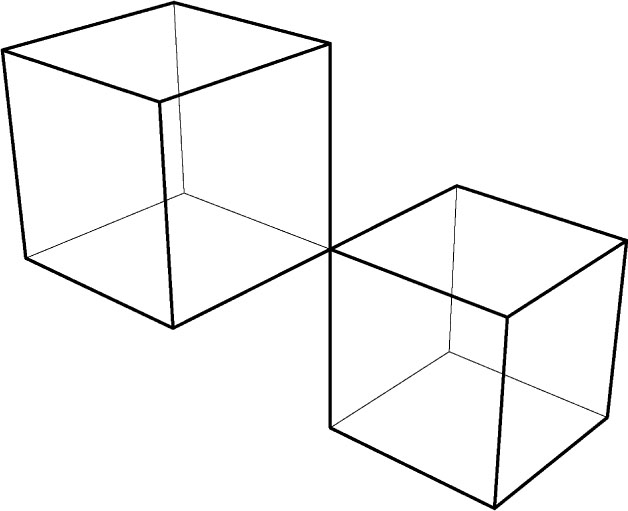
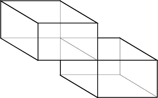
On the other hand, the double cube of Figure 7.7 has 15 vertices, 24 edges, and 12 faces which yield

The reason for this is of course that this is not a proper polyhedron. Other exceptions can be easily constructed but they all involve some feature that could call their “solidity” into question.
1.Answer the following questions for each of the solids obtained from the octahedron by the first truncation methods described in Figure 7.5 (parts a, b, c are to be answered without reference to Euler’s equation):
(a)How many vertices does it have?
(b)How many edges does it have?
(c)What regular polygons appear as its faces and how many times?
(d)Identify the truncated solid in Figure 7.3 or in Figure 7.1.
(e)Verify that the cells of this solid satisfy Euler’s equation.
2.Repeat Exercise 1 for the tetrahedron.
3.Repeat Exercise 1 for the dodecahedron.
4.Repeat Exercise 1 for the icosahedron.
5.Answer the following questions for each of the solids obtained from the octahedron by the second truncation methods described in Figure 7.6 (parts a, b, c are to be answered without reference to Euler’s equation):
(a)How many vertices does it have?
(b)How many edges does it have?
(c)What regular polygons appear as its faces and how many times?
(d)Identify the truncated solid in Figures 7.3, 7.4 or in Figure 7.1.
(e)Verify that the cells of this solid satisfy Euler’s equation.
6.Repeat Exercise 5 for the tetrahedron.
7.Repeat Exercise 5 for the dodecahedron.
8.Repeat Exercise 5 for the icosahedron.
9.The truncation procedure that produced the truncated cube I can be applied to arbitrary solids so as to obtain new solids. Without using Euler’s equation find the number of vertices, edges, and faces of the solids obtained by applying this procedure to each of the solids below. Also verify Euler’s equation for each derived solid.
(a)the two truncated cubes
(b)the two truncated tetrahedra
(c)the two truncated octahedra
(d)the two truncated dodecahedra
(e)the two truncated icosahedra
(f)a solid with v vertices, e edges, and f faces, in which each vertex is incident to d edge
10.The truncation procedure that produced the truncated cube II can be applied to arbitrary solids so as to obtain new solids. Find the number of vertices, edges, and faces of the solids obtained by applying this procedure to each of:
(a)the two truncated cubes
(b)the two truncated tetrahedra
(c)the two truncated octahedra
(d)the two truncated dodecahedra
(e)the two truncated icosahedra
(f)a solid with v vertices, e edges, and f faces, in which each vertex is incident to d edges.
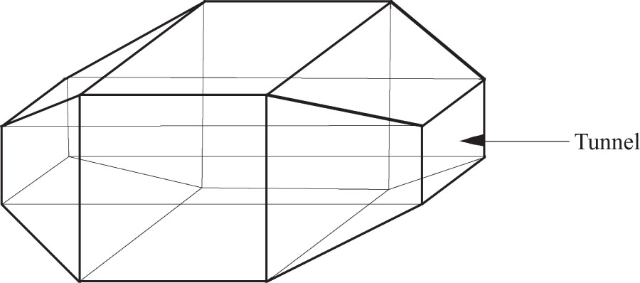
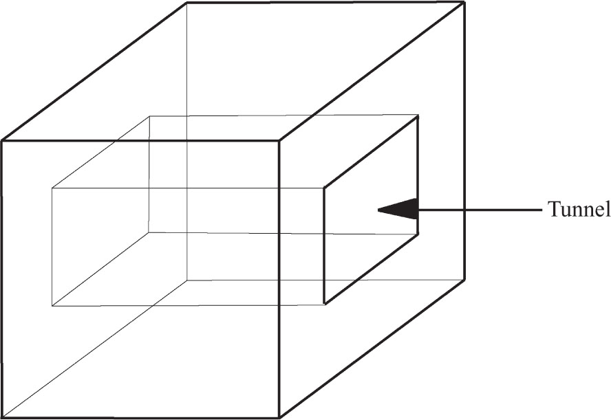
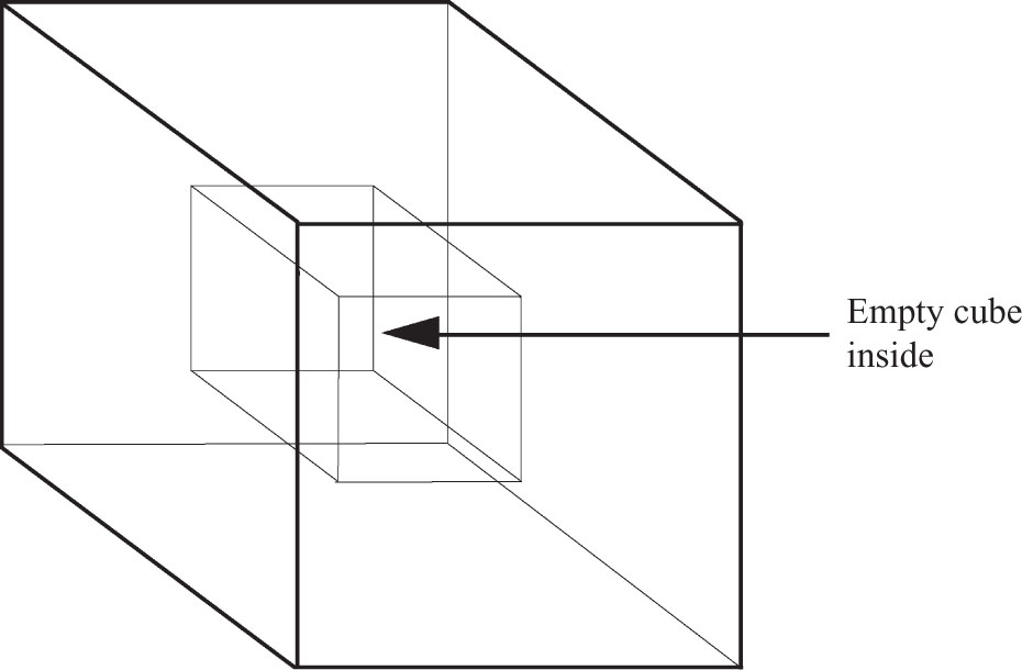
11.Show that the cell counts of the solid of Figure 7.8 do not satisfy Euler’s equation. Explain why this is not a counterexample to this equation.
12.Show that the cell counts of the solid of Figure 7.9 do not satisfy Euler’s equation. Explain why this is not a counterexample to this equation.
13.Show that the cell counts of the solid of Figure 7.10 do not satisfy Euler’s equation. Explain why this is not a counterexample to this equation.
14.Show that the cell counts of the solid of Figure 7.11 do not satisfy Euler’s equation. Explain why this is not a counterexample to this equation.
15.Construct a cube using the medium of your choice.
16.Construct a tetrahedron using the medium of your choice.
17.Construct an octahedron using the medium of your choice.
18.Construct a dodecahedron using the medium of your choice.
19.Construct an icosahedron using the medium of your choice.
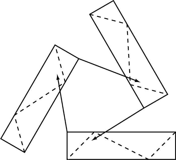
20.A paper model of the dodecahedron can be constructed from thirty square sheets of paper (8.5″ by 8.5″ is easy to work with). Each piece should be folded in half and then each half is to be folded in half again, accordion fashion. Next, fold each piece along the dashed lines indicated below, where the two corners are isosceles right triangles. These last three folds should all bend toward you. The pieces are to be tucked into each other as indicated in Figure 7.12 so that short dashed lines fall along long dashed lines.
21.Construct all thirteen Archimedean polyhedra using the medium of your choice.
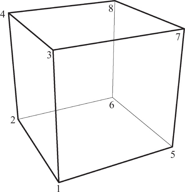
A symmetry of a polyhedron is a rotation of that solid’s ambient space that ends with the solid in its exact original position. During the rotation the polyhedron may very well pass through nearby parts of space that it did not occupy initially, but once the rotation is completely carried out the solid’s position must coincide exactly with its initial position. Every such rotation of course has an axis and an (oriented) angle of rotation. The axes of those rotations that constitute symmetries of some polyhedron are constrained by the fact that they must pass through a vertex, the midpoint of an edge, or else the center of some face. This observation is used to label the rotations. Thus, R3,• denotes a symmetry of the cube whose axis passes through the vertex at 3, R23,• denotes a symmetry of the cube whose axis passes through the midpoint of the edge 23, and R3487,• denotes a symmetry of the cube whose axis passes through the center of the square 3487. This notation is subject to some redundancy. Thus, for the cube, the symmetry R3,• can also be written as R5,•, the symmetry R23,• can also be written as R58,•, and the symmetry R3487,• can also be written as R1265,•.
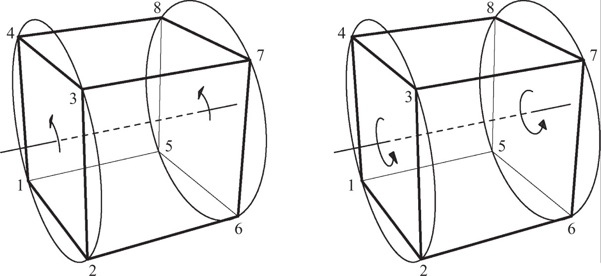
The angle of a rotation is also incorporated into its symbol. Thus RA,α denotes a rotation by the oriented angle α where the orientation is understood to be determined by an observer positioned outside the solid near A. Thus, R1234,90° denotes the 90° rotation of the cube about the axis that passes through the centers of the squares 1234 and 5678, counterclockwise from the point of view of an observer situated outside the cube near the face 1234 (Figure 7.13). Note that since −90° denotes a clockwise rotation it follows that R1234,90° = R5678,−90°. The circles in the illustrations are meant to help visualize the rotation; they are the “tracks” in which the vertices move to their new positions.
From Rotations to Permutations. It is convenient to represent rotations by their effect on vertices. Thus, since the rotation R1234,90°, cycles the vertices in positions 1, 2, 3, 4 and also the vertices in positions 5, 6, 7, 8, it has the permutation representation (1 2 3 4)(5 6 7 8) as well as

and many others, all of which are considered as the same permutation.
Similarly, the 180° rotation R1234,180° has, amongst others, the following permutation representations:

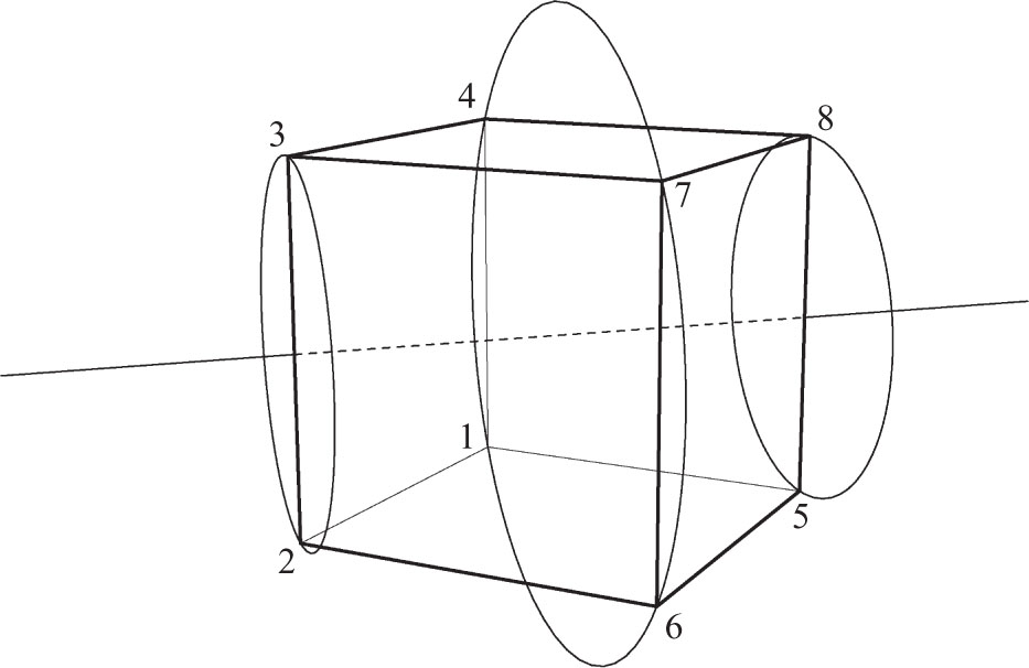
A qualitatively different symmetry of the cube is obtained by a 180° rotation about an axis that passes through the midpoints of two diametrically opposite edges of the cube. Such, for example, is the rotation R23,180° = R58,180° of Figure 7.14. It has the permutation representation (1 7)(4 6)(2 3)(5 8). While this permutation looks very much like that of R1265,180° above, there is a significant geometrical difference between them. The permutation representation (1 7)(4 6)(2 3)(5 8) of R23,180° has cycles that are in fact cells of the cube, namely (2 3) and (5 8). On the other hands, none of the cycles of the permutation representation (1 3) (2 4)(5 7)(6 8) of R1234,180° are cells of the cube.
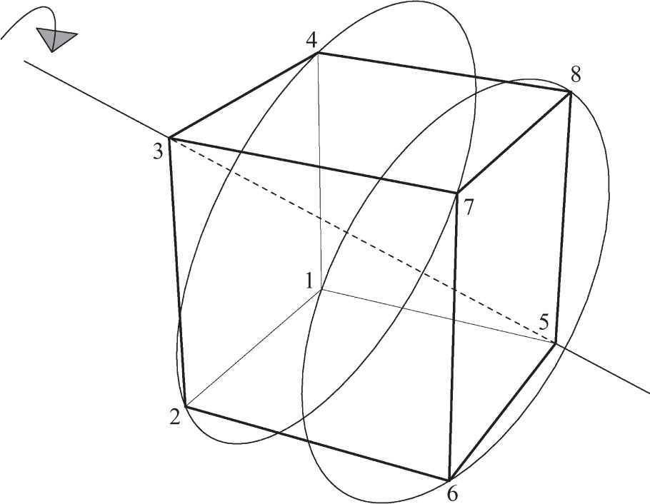
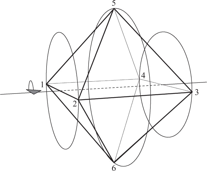
Yet another kind of symmetry is obtained by using a diagonal of the cube as axis. The rotation R3,120° (Figure 7.15) has the diagonal 35 as its axis and the angle of the rotation is 120°. A permutation representation of this rotation is (1 6 8)(2 7 4) (3)(5).
The set of symmetries of a polyhedron is called its symmetry group and the number of such symmetries is the order of this symmetry group. Note that the identity is trivially a symmetry of every polyhedron and so the order of every symmetry group is at least one. The information garnered above about the symmetry group of the cube is now summarized.
Proposition 7.2.1. The symmetry group of the cube has order 24 and its symmetries are classified as:
Id
4 symmetries of each of the types Rvertex,120° and Rvertex,−120°
6 symmetries of the type Redge,180°
3 symmetries of each of the types Rface,90°, Rface,180°, Rface,−90°
From Permutations to Rotations. It will soon be necessary to work in the reverse direction and to identify a rotation from its permutation representation. This is an easy matter if one keeps the following observation in mind:
Proposition 7.2.2. If a cycle of a permutation representation of a rotation is also a cell of the polyhedron, then the axis of the rotation passes through the center of that cell.
Consider, for example, the permutation (1 5)(2 8)(3 7)(4 6) of the cube of Figure 7.16. Note that the cycles (1 5) and (3 7) are actually cells of this cube whereas that is not the case for the cycles (2 8) and (4 6). It follows from the above observation that the axis of the corresponding rotation passes through the centers of (1 5) and (3 7) and so it is of the type R15, • or R37, •. The angle of the rotation must be 180° because this symmetry must interchange 1 and 5 as well as 3 and 7. This symmetry is therefore R15,180° = R37,180°.
Similarly, the permutation (1 3 8)(2 7 5)(4)(6) has the cycles (4) and (6) which correspond to the vertices 4 and 6 of the cube and so its rotation must be of the form R4,• or R6,•. As noted in Proposition 7.2.1, the angle of such a rotation is either 120° or −120°. To determine the angle we examine the rotation from the point of view of the vertex 6 since it is easier for us to see things from this point of view rather than that of 4. The neighbors of 6, i.e., the vertices connected to 6 by edges, are rotated according to the cycle (2 7 5), which from the point of view of 6, is a counterclockwise rotation. This permutation therefore represents the rotation R6,120°. Alternately, this rotation moves the three neighbors of 4 according to the cycle (1 3 8), which, from the point of view of 4, is a clockwise rotation (this is somewhat harder to visualize, which is the reason it was suggested that we work with the vertex 6 instead). Hence the same rotation can be written as R4,−120°.
The only type of rotation for which Proposition 7.2.2 fails to yield the axis directly is that of R1234,180° = (1 3)(2 4)(5 7)(6 8). However, this uniqueness makes it easy to identify rotations of this type. For example, none of the cycles of the permutation (1 8)(2 7)(3 6)(4 5) is a cell of the cube of Figure 7.16. Consequently, this is a rotation of type Rabcd,180°. Since this rotation interchanges vertices 1 and 8, it must be R1485,180°. On the other hand, the permutation (1 7)(2 6)(3 5)(4 8) has two cycles (2 6) and (4 8) which are also cells and hence it is the rotation R26,180°.
The Composition of Rotations. The interaction of symmetries is of particular interest to both mathematicians and physicists. These interactions are easily described by means of the permutation representations of the symmetries in question. For this purpose we digress here to discuss the composition of permutations in general. If τ and σ are two permutations (or rotations) then τoσ denotes their combined effect then they are applied successively, first τ and then σ, to the same solid. For example, working with τ = R1265,90° = (1 2 6 5)(4 3 7 8) and σ = R2376,180° = (2 7) (3 6)(4 5)(1 8) we have

where the computation goes as follows:
| τ rotates | σ rotates | so τoσ takes |
| 1 to 2 | 2 to 7 | 1 to 7 |
| 7 to 8 | 8 to 1 | 7 to 1 |
| 2 to 6 | 6 to 3 | 2 to 3 |
| 3 to 7 | 7 to 2 | 3 to 2 |
| 6 to 5 | 5 to 4 | 6 to 4 |
| 4 to 3 | 3 to 6 | 4 to 6 |
| 5 to 1 | 1 to 8 | 5 to 8 |
| 8 to 4 | 4 to 5 | 8 to 5 |
The first two rows of the array above tell us that (1 7) is a cycle of τoσ. The next six rows, taken two at a time, show that (2 3), (4 6), (5 8) are also cycles of τoσ. Consequently,
or

Similarly,

Or,

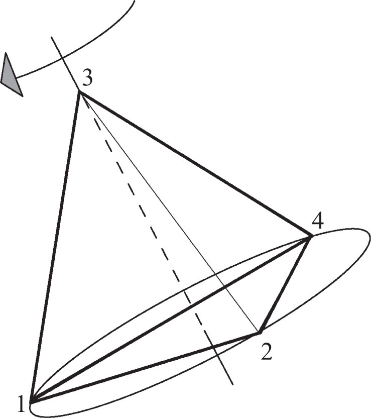
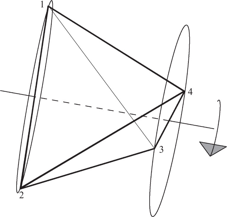
Whereas the axis of any symmetry of the cube joins the midpoints of cells of the same dimension, the tetrahedron presents us with a new alternative. The axis of the symmetry R3,−120° joins the vertex 1 to the center of the triangular face with vertices 1, 2, and 4. This symmetry has the permutation representation (1 4 2)(3). The only qualitatively different symmetry of the tetrahedron is the 180° rotation about the line joining the midpoints of two opposite edges. Such, for example, is R24,180° = (1 3)(2 4). Note that

The symmetries of the tetrahedron are illustrated in Figures 7.17–7.18 and hereby summarized.
Proposition 7.2.3.The symmetry group of the tetrahedron has order 12 and its symmetries are classified as:
Id
4 symmetries of each of the types Rvertex,120° and Rvertex,240°
3 symmetries of the type Redge,180°
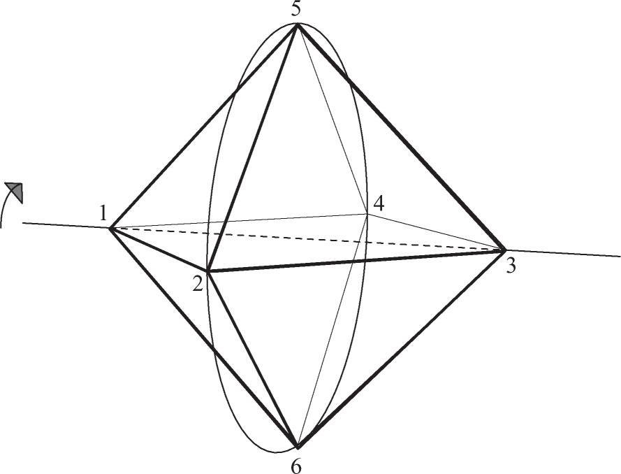
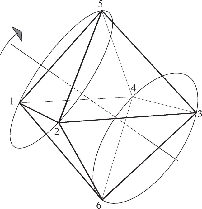
We close this section with a display of the three types of symmetries of the octahedron (Figures 7.19–7.21).
1.The symmetry group of the octahedron has order 24 and its symmetries are classified as:
(a)Id
(b)3 symmetries of each of the types Rvertex,90°, Rvertex,180°, Rvertex,−90°
(c)6 symmetries of the type Redge,180°
(d)4 symmetries of each of the types Rface,90°, Rface,180°, Rface,−90°
(e)Using Figures 7.18–7.20, display all the rotations of the octahedron as permutations.
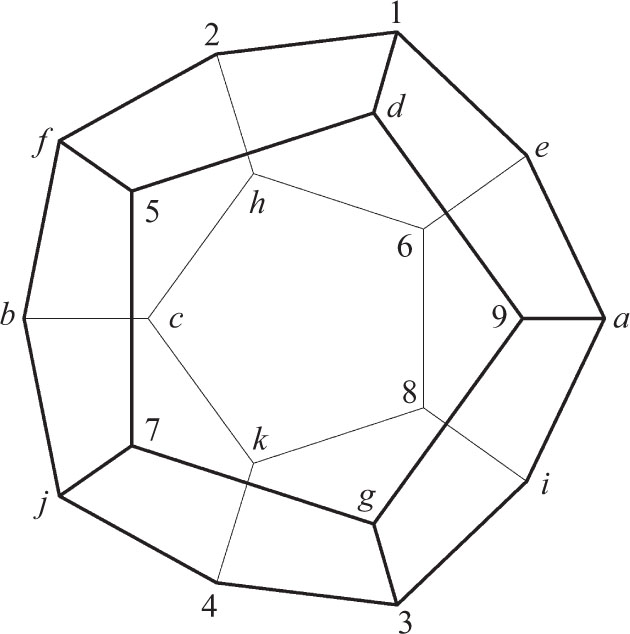
2.Classify the symmetries of the dodecahedron of Figure 7.22.
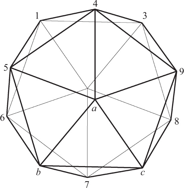
3.Classify the symmetries of the icosahedron of Figure 7.23.
4.Suppose A = R26,180°, B = R1,120°, C = R2376,90°, D = R1234,180° are symmetries of the cube of Figure 7.16.
(a)Find the permutation representations of A, B, C, D.
(b)Identify the following symmetries:
i)A◦A
ii)A◦B
iii)A◦C
iv)A◦D
v)B◦A
vi)B◦B
vii)B◦C
viii)B◦D
ix)C◦A
x)C◦B
xi)C◦C
xii)C◦D
xiii)D◦A
xiv) D◦B
xv)D◦C
xvi) D◦D
5.Repeat Exercise 4 with A = R15,180°, B, = R2,−120° C = R3487,270°, D = R5678,180°.
6.Suppose A= R24,180°, B= R 1,120°, C= R2,240°, D= R14,180° are symmetries of the tetrahedron of Figure 7.17.
(a)Find the permutation representations of A, B, C, D.
(b)Identify the following symmetries:
i)A◦A
ii)A◦B
iii)A◦C
iv)A◦D
v)B◦A
vi) B◦B
vii)B◦C
viii)B◦D
ix)C◦A
x)C◦B
xi)C◦C
xii)C◦D
xiii)D◦A
xiv)D◦B
xv) D◦C
xvi)D◦D
7.Repeat Exercise 6 with A = R23,180°, B = R3,120°, C = R3,240°, D = R12,180°.
8.Suppose A= R25,180°, B = R1,90°, = R1,90°, C = R235,240°, D = R4,180° are symmetries of the octahedron of Figure 7.19.
(a)Find the permutation representations of A, B, C, D.
(b)Identify the following symmetries:
i)A◦A
ii)A◦B
iii)A◦C
iv)A◦D
v)B◦A
vi)B◦B
vii)B◦C
viii)B◦D
ix)C◦A
x)C◦B
xi)C◦C
xii)C◦D
xiii)D◦A
xiv)D◦B
xv)D◦C
xvi)D◦D
9.Repeat Exercise 8 with A = R46,180°, B = R1,180°, C = R345,120°, D = R6,90°.
10.Suppose A = R57,120°, B = R5,120°, C = R57jbf,72°, D = R1d5f2,144° are symmetries of the dodecahedron of Figure 7.22.
(a)Find the permutation representations of A, B, C, D.
(b)Identify the following symmetries:
i)A◦A
ii)A◦B
iii)A◦C
iv)A◦D
v)B◦A
vi)B◦B
vii)B◦C
viii)B◦D
ix)C◦A
x)C◦B
xi)C◦C
xii)C◦D
xiii)D◦A
xiv)D◦B
xv)D◦C
xvi)D◦D
11.Repeat Exercise 10 with A = R1,240°, B = Rbj,180°, C = R68iae,144°, D = R2fbch,72°.
12.Suppose A= R1,72°, B= R4a,180°, C= R349,240°, D= R4,144° are symmetries of the icosahedron of Figure 7.23.
(a)Find the permutation representations of A, B, C, D.
(b)Identify the following symmetries:
i)A◦A
ii)A◦B
iii)A◦C
iv)A◦D
v)B◦A
vi)B◦B
vii)B◦C
viii)B◦D
ix)C◦A
x)C◦B
xi)C◦C
xii)C◦D
xiii)D◦A
xiv)D◦B
xv)D◦C
xvi)D◦D
13.Repeat Exercise 12 with A = R1,144°, B = R89,180°, C = R126,120°, D = Ra,144°.
14.None of the faces of a rectangular box are square. How many symmetries does it have?
15.Two of the faces of a rectangular box are square. How many symmetries does it have?
16.How many symmetries does a triangular prism with an equilateral base have?
17.How many symmetries does a triangular prism have if its base has sides 6, 6, 4?
18.How many symmetries does a prism have if its base is a regular n-gon?
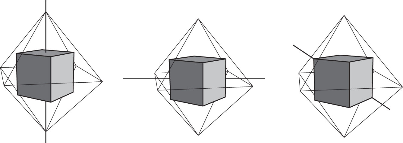
The previous section described the symmetries of the cube and the octahedron separately. Those of the cube were listed in Proposition 7.2.1 whereas those of the octahedron were relegated to Exercise 7.2.1. Superficially, the symmetries of the cube are permutations of eight vertices whereas those of the octahedron are permutations of six vertices. Nevertheless, there is a sense in which these two groups are identical. Observe that in Figure 7.24 a cube has been placed inside an octahedron so that each of the vertices of the first is the center of a square face of the latter. The possibility of this placement implies that every Rface,• symmetry of the cube is also an Rvertex,• symmetry of the octahedron. Similarly, every Redge,• symmetry of the cube is also an Redge,• symmetry of the octahedron and every Rvertex,• symmetry of the cube is an Rface,• symmetry of the octahedron. Thus, Figure 7.24 reveals that the symmetry groups of the cube and the octahedron are identical. Technically, they are said to be isomorphic. It is clear that isomorphic groups must have the same order and so the symmetry groups of the cube and the tetrahedron are nonisomorphic, as they have groups of orders 24 and 12, respectively. Groups of the same order need not be isomorphic either. This is demonstrated by the symmetry group of the regular 12-gon. Just like the cube, this polygon has 24 symmetries. However, the 30° rotation of this polygon is a symmetry of order 12 and no symmetry of the cube has such an order. Hence the symmetry groups of the regular 12-gon and the cube are non-isomorphic, even though they have the same orders.
Group theory, the mathematical theory of symmetry, has its origins in the work of Joseph Louis Lagrange (1736–1813) on the theory of equations. It was later used by Niels Henrik Abel (1802–1829) and Évariste Galois (1811–1832) to settle the question of which equations could be solved by explicit algebraic formulas and which could only be solved by means of successive approximations. It was the investigations of Felix Klein (1849–1925) and Henri Poincaré (1854–1912) that pointed out the central role that symmetry plays in geometry.
One of the main targets of group theory is the classification of all groups up to isomorphism. While there is no expectation that this goal will be achieved in the foreseeable future, a significant milestone was passed less than twenty years ago when the finite simple groups were completely classified. There is nothing simple about the simple groups, nor is it possible to characterize them in this text. The symmetries of the icosahedron (and the dodecahedron) constitute a simple group whereas the groups of the cube and tetrahedron are not simple, but this difference does not have a geometrical interpretation. Algebraically, though, the difference is extremely important. The simplicity of the dodecahedral group turns out to be responsible for the non-existence of a formulaic solution for the general fifth degree equation

Conversely, the non-simplicity of the rotation groups of the octahedron, cube and tetrahedron implies the existence of such a formula for the fourth degree equation

The classification of the finite simple groups constitutes the most monumental task ever accomplished by mathematicians. Its proof is spread over 500 articles comprising more than 14,000 journal pages written by hundreds of researchers. This classification asserts that the finite simple groups fall into two categories: several infinite families of groups that possess clear patterns and 26 exceptional groups, known as the sporadic groups, for which no general pattern has been found.
The first of the sporadic groups was discovered in 1861 and the last two almost simultaneously in 1980. The largest of these was nicknamed MONSTER because of its order which is

MONSTER, discovered by Bernd Fischer and Robert L. Griess, is the group of symmetries of a (non-regular) solid in 196,883 dimensions. When word of this discovery reached John McKay, he pointed out the remarkable coincidence that the number 196,884 plays an important role in the theory of the patterns that underlie non-Euclidean wallpaper designs. As mathematicians were at a loss to explain this conjunction they dubbed the following equation as McKay’s Formula:

John H. Conway assigned the name Moonshine to this and other related unexplained phenomena in 1979 “… intending the word to convey our feelings that they are seen in a dim light, and that the whole subject is rather vaguely illicit.” It should be remembered that at that time the existence of MONSTER had only been conjectured so that even the number 196,883 was questionable, not to mention its purported relation with non-Euclidean geometry.
The existence of MONSTER was conclusively demonstrated in 1980 by R. Griess who tried, unsuccessfully, to change its name to The Friendly Giant. Monstrous Moonshine Mathematics was finally explained by Richard E. Borcherds who found the connection in the theory of Vertex Algebras, a discipline developed recently for the purpose of providing a mathematical foundation to the new and controversial Superstring Theory of physics. For this work Borcherds received the 1998 Fields Medal, the most prestigious award bestowed by the mathematical community.
1.Construct dodecahedra in class as described in Exercise 7.1.20. Have each student prepare a dozen folded strips before class and let them work in groups of three.
2.Use the Triangle Tiler at the Geometry Center at the ScienceU.com website to draw the five regular solids.
3.Use the Triangle Tiler at the Geometry Center at the ScienceU.com website to draw all the semiregular solids that can be obtained from the regular ones by truncation.